light MAZDA 6 2002 Suplement Owner's Guide
[x] Cancel search | Manufacturer: MAZDA, Model Year: 2002, Model line: 6, Model: MAZDA 6 2002Pages: 909, PDF Size: 17.16 MB
Page 201 of 909
FUEL SYSTEM
F2–49
F2
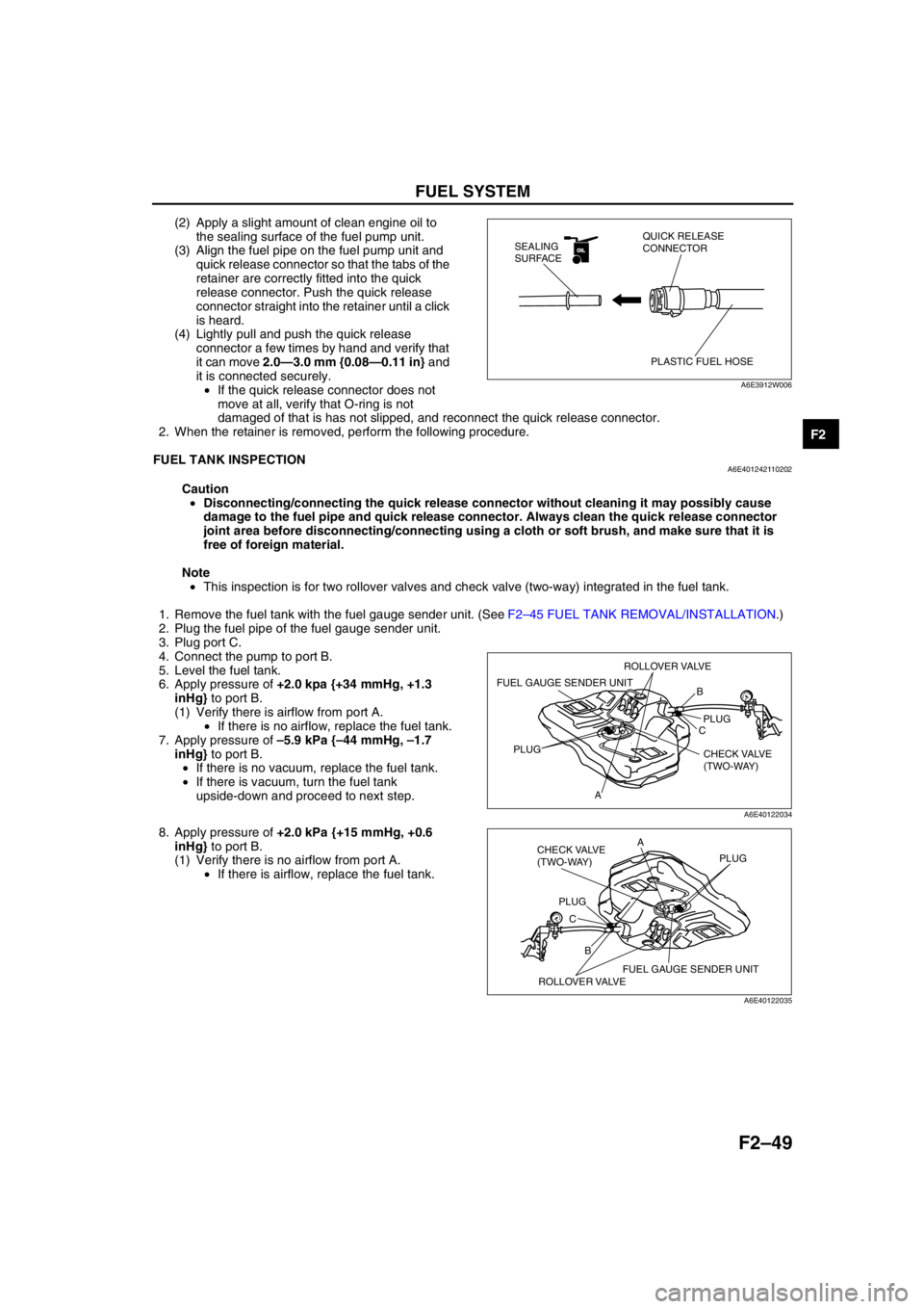
(2) Apply a slight amount of clean engine oil to
the sealing surface of the fuel pump unit.
(3) Align the fuel pipe on the fuel pump unit and
quick release connector so that the tabs of the
retainer are correctly fitted into the quick
release connector. Push the quick release
connector straight into the retainer until a click
is heard.
(4) Lightly pull and push the quick release
connector a few times by hand and verify that
it can move 2.0—3.0 mm {0.08—0.11 in} and
it is connected securely.
•If the quick release connector does not
move at all, verify that O-ring is not
damaged of that is has not slipped, and reconnect the quick release connector.
2. When the retainer is removed, perform the following procedure.
End Of Sie
FUEL TANK INSPECTIONA6E401242110202
Caution
•Disconnecting/connecting the quick release connector without cleaning it may possibly cause
damage to the fuel pipe and quick release connector. Always clean the quick release connector
joint area before disconnecting/connecting using a cloth or soft brush, and make sure that it is
free of foreign material.
Note
•This inspection is for two rollover valves and check valve (two-way) integrated in the fuel tank.
1. Remove the fuel tank with the fuel gauge sender unit. (See F2–45 FUEL TANK REMOVAL/INSTALLATION.)
2. Plug the fuel pipe of the fuel gauge sender unit.
3. Plug port C.
4. Connect the pump to port B.
5. Level the fuel tank.
6. Apply pressure of +2.0 kpa {+34 mmHg, +1.3
inHg} to port B.
(1) Verify there is airflow from port A.
•If there is no airflow, replace the fuel tank.
7. Apply pressure of –5.9 kPa {–44 mmHg, –1.7
inHg} to port B.
•If there is no vacuum, replace the fuel tank.
•If there is vacuum, turn the fuel tank
upside-down and proceed to next step.
8. Apply pressure of +2.0 kPa {+15 mmHg, +0.6
inHg} to port B.
(1) Verify there is no airflow from port A.
•If there is airflow, replace the fuel tank.
End Of Sie
OILOIL
PLASTIC FUEL HOSE QUICK RELEASE
CONNECTOR SEALING
SURFACE
A6E3912W006
B
C
APLUG
PLUG
CHECK VALVE
(TWO-WAY)
FUEL GAUGE SENDER UNIT
ROLLOVER VALVE
A6E40122034
B CA
PLUGPLUG
CHECK VALVE
(TWO-WAY)
FUEL GAUGE SENDER UNIT
ROLLOVER VALVE
A6E40122035
Page 326 of 909
F2–174
TROUBLESHOOTING
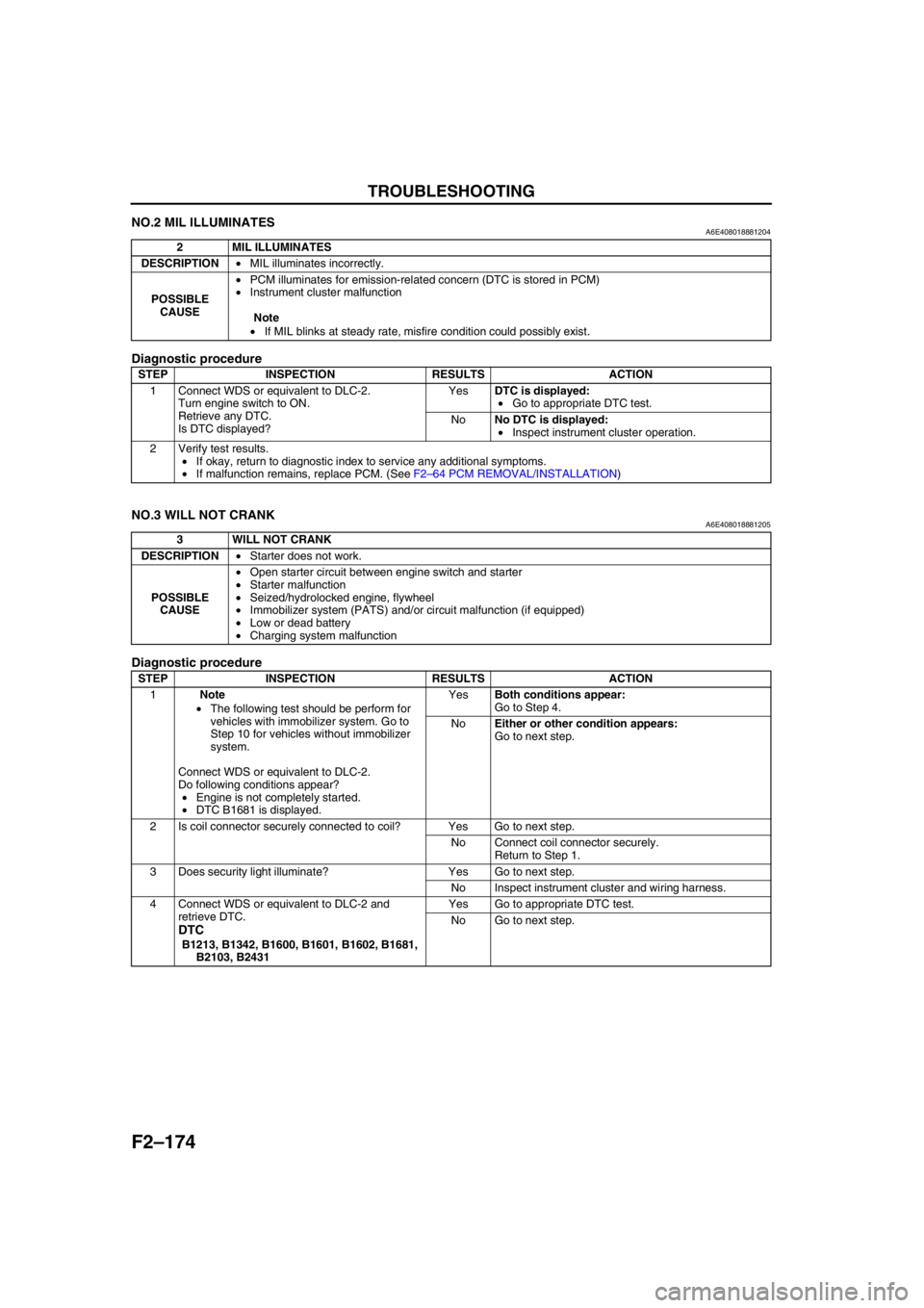
NO.2 MIL ILLUMINATESA6E408018881204
Diagnostic procedure
End Of Sie
NO.3 WILL NOT CRANKA6E408018881205
Diagnostic procedure
2 MIL ILLUMINATES
DESCRIPTION•MIL illuminates incorrectly.
POSSIBLE
CAUSE•PCM illuminates for emission-related concern (DTC is stored in PCM)
•Instrument cluster malfunction
Note
•If MIL blinks at steady rate, misfire condition could possibly exist.
STEP INSPECTION RESULTS ACTION
1 Connect WDS or equivalent to DLC-2.
Turn engine switch to ON.
Retrieve any DTC.
Is DTC displayed?YesDTC is displayed:
•Go to appropriate DTC test.
NoNo DTC is displayed:
•Inspect instrument cluster operation.
2 Verify test results.
•If okay, return to diagnostic index to service any additional symptoms.
•If malfunction remains, replace PCM. (See F2–64 PCM REMOVAL/INSTALLATION)
3 WILL NOT CRANK
DESCRIPTION•Starter does not work.
POSSIBLE
CAUSE•Open starter circuit between engine switch and starter
•Starter malfunction
•Seized/hydrolocked engine, flywheel
•Immobilizer system (PATS) and/or circuit malfunction (if equipped)
•Low or dead battery
•Charging system malfunction
STEP INSPECTION RESULTS ACTION
1Note
•The following test should be perform for
vehicles with immobilizer system. Go to
Step 10 for vehicles without immobilizer
system.
Connect WDS or equivalent to DLC-2.
Do following conditions appear?
•Engine is not completely started.
•DTC B1681 is displayed.YesBoth conditions appear:
Go to Step 4.
NoEither or other condition appears:
Go to next step.
2 Is coil connector securely connected to coil? Yes Go to next step.
No Connect coil connector securely.
Return to Step 1.
3 Does security light illuminate? Yes Go to next step.
No Inspect instrument cluster and wiring harness.
4 Connect WDS or equivalent to DLC-2 and
retrieve DTC.
DTC
B1213, B1342, B1600, B1601, B1602, B1681,
B2103, B2431Yes Go to appropriate DTC test.
No Go to next step.
Page 330 of 909

F2–178
TROUBLESHOOTING
End Of Sie
NO.5 ENGINE STALLS-AFTER START/AT IDLEA6E408018881207
Diagnostic Procedure
18 Verify test results.
•If okay, return to diagnostic index to service any additional symptoms.
•If malfunction remains, replace PCM. (See F2–64 PCM REMOVAL/INSTALLATION) STEP INSPECTION RESULTS ACTION
5 ENGINE STALLS-AFTER START/AT IDLE
DESCRIPTION•Engine stops unexpectedly.
POSSIBLE
CAUSE•Poor fuel quality
•Intake-air system restriction or clogging
•Engine overheating
•A/C system improper operation
•Immobilizer system (PATS) and/or circuit malfunction (if equipped)
•PCM control relay malfunction
•Glow system malfunction
•Inadequate fuel pressure
•Fuel pressure sensor related circuit malfunction
•Suction control valve malfunction (built-in supply pump)
•Fuel pressure limiter malfunction (built-in common rail)
•Fuel leakage
•Fuel line clogging or restriction
•Fuel filter clogging or restriction
•Incorrect fuel injection timing
•Erratic signal from CKP sensor
•Erratic signal from CMP sensor
•Supply pump malfunction
•Fuel injector malfunction
•Low engine compression
•Improper valve timing
•Exhaust system and/or catalyst converter restriction or clogging
•EGR system malfunction
•ECT sensor or related circuit malfunction
•Accelerator positions sensor or related circuit malfunction
•Accelerator positions sensor misadjustment
•MAF/IAT sensor or related circuit malfunction
•V-reference voltage supply circuit malfunction
•IDM or related circuit malfunction
Warning
The following troubleshooting flow chart contains the fuel system diagnosis and repair
procedures. Read the following warnings before performing the fuel system services:
•Fuel vapor is hazardous. It can easily ignite, causing serious injury and damage. Always keep
sparks and flames away from fuel.
•Fuel line spills and leakage are dangerous. Fuel can ignite and cause serious injury or death
and damage. Fuel can also irritate skin and eyes. To prevent this, always complete “BEFORE
REPAIR PROCEDURE” and “AFTER REPAIR PROCEDURE” described in this manual.
STEP INSPECTION RESULTS ACTION
1Note
•The following test should be perform for
vehicles with immobilizer system. Go to
Step 10 for vehicles without immobilizer
system.
Connect WDS or equivalent to DLC-2.
Do following conditions appear?
•Engine is not completely started.
•DTC B1681 is displayed.YesBoth conditions appear:
Go to Step 4.
NoEither or other condition appears:
Go to next step.
2 Is coil connector securely connected to coil? Yes Go to next step.
No Connect coil connector securely.
Return to Step 1.
3 Does security light illuminate? Yes Go to next step.
No Inspect instrument cluster and wiring harness.
Page 332 of 909
F2–180
TROUBLESHOOTING
15 Is there any restriction in exhaust system or
catalyst converter?Yes Repair or replace as necessary.
No Go to next step.
16 Access RPM PID.
Is RPM PID indicating engine speed during
cranking engine?Yes Go to next step.
No Go to Step 19.
17Note
•The following test should be performed on
the vehicles with A/C system. If the
following test cannot be performed due to
engine stalling, go to next step.
•Go to next step for the vehicle without A/C
system.
Connect pressure gauge to A/C line.
Turn blower and A/C switches on.
Is pressure within specifications?Yes Go to next step.
NoA/C is always on:
Go to symptom troubleshooting “NO.24 A/C ALWAYS
ON OR A/C COMPRESSOR RUNS
CONTINUOUSLY”.
Other symptoms:
Inspect following:
•Refrigerant charging amount
•Cooling fan No.1 and/or cooling fan No.2 operation
18 Inspect adjustment of accelerator position
sensor and idle switch.
(See F2–72 ACCELERATOR POSITION
SENSOR INSPECTION)
(See F2–70 IDLE SWITCH INSPECTION)
Are accelerator position sensor and idle switch
adjusted correctly?Yes Go to next step.
No Adjust accelerator position sensor and idle switch
correctly.
(See F2–73 ACCELERATOR POSITION SENSOR
ADJUSTMENT)
(See F2–71 IDLE SWITCH ADJUSTMENT)
19 Depress accelerator pedal slightly.
Crank engine.
Does engine start now?Yes Inspect idle speed.
(See F2–34 IDLE SPEED INSPECTION)
No Go to next step.
20 Inspect for fuel leakage from fuel pipe.
Is any fuel leakage found on fuel pipe?Yes Repair or replace as necessary.
No Go to next step.
21 Visually inspect CKP sensor and teeth of pulse
wheel.
Are CKP sensor and teeth of pulse wheel okay?Yes Go to next step.
No Replace malfunctioning parts.
22 Measure gap between CKP sensor and teeth of
pulse wheel.
Specification
1.5—2.5 mm {0.059—0.098 in}
Is gap within specification?Yes Go to next step.
No Adjust CKP sensor position.
23 Visually inspect CMP sensor and teeth of pulse
wheel.
Are CMP sensor and teeth of pulse wheel okay?Yes Inspect following PIDs:
(See F2–65 PCM INSPECTION)
•ECT
•IAT
•MAF
•RPM
If PID value is not as specified, repair or replace
malfunctioning parts.
If PID value is okay, go to next step.
No Replace malfunctioning parts.
24 Inspect fuel pressure sensor.
(See F2–79 FUEL PRESSURE SENSOR
INSPECTION)
Is fuel pressure okay?Yes Go to next step.
No Replace common rail.
25 Inspect suction control valve.
(See F2–54 SUCTION CONTROL VALVE
INSPECTION)
Is suction control valve okay?Yes Go to next step.
No Repair supply pump.
(See F2–54 SUPPLY PUMP INSPECTION)
26 Is engine compression correct?
(See B2–8 COMPRESSION INSPECTION)Yes Go to next step.
No Inspect for following:
•Damaged valve seat
•Worn valve stem and valve guide
•Worn or stuck piston ring
•Worn piston, piston ring or cylinder
•Improper valve timing
Service as necessary.
27 Inspect fuel injector.
(See F2–56 FUEL INJECTOR INSPECTION)
Is fuel injector okay?Yes Go to next step.
No Repair or replace as necessary. STEP INSPECTION RESULTS ACTION
Page 334 of 909

F2–182
TROUBLESHOOTING
3 Does security light illuminate? Yes Go to next step.
No Inspect instrument cluster and wiring harness.
4 Connect WDS or equivalent to DLC-2 and
retrieve DTC.
DTC
B1213, B1342, B1600, B1601, B1602, B1681,
B2103, B2431Yes Go to appropriate DTC test.
No Go to next step.
5 Is there continuity between PCM GND terminals
65, 85, 103, 104 and GND?Yes Go to next step.
No Repair or replace wiring harness.
6 Measure voltage between PCM GND terminals
65, 85, 103, 104 and coil terminal C.
Is the voltage below 1.0?Yes Go to next step.
No Repair or replace wiring harness.
7 Turn engine switch to ON.
Access VPWR PID.
Is VPWR PID okay?
Specification
Battery voltageYes Go to next step.
No Repair or replace wiring harness.
8 Disconnect coil connector.
Turn engine switch to ON.
Is there battery voltage at coil connector terminal
D (harness-side)?Yes Inspect for following:
•Open or short circuit between coil terminal A and
PCM terminal 80
•Open or short circuit between coil terminal B and
PCM terminal 28
No Repair or replace wiring harness between coil
connector terminal D and fuse panel.
9 Is there continuity between PCM terminal 57 and
starter relay?Yes Go to next step.
No Repair replace wiring harness.
10 Inspect for following:
•Fuel quality (e.g.: include water
contamination, winter/summer blend)
•Fuel line/fuel filter clogging
•Intake-air system restriction
Are all items okay?Yes Go to next step.
No Service as necessary.
Repeat Step 10.
11Note
•Ignore DTC P0122, P0123, P0222 or
P0223 while performing this test.
Disconnect accelerator position sensor
connector.
Measure voltage at accelerator position sensor
connector VREF terminal (terminal D) with
engine switch ON.
Specification
4.5—5.5 V
Is voltage okay?Yes Go to next step.
No Go to symptom troubleshooting “NO.26 CONSTANT
VOLTAGE”.
12 Connect WDS or equivalent to DLC-2.
Turn engine switch to ON.
Retrieve any DTC.
Is DTC displayed?YesDTC is displayed:
Go to appropriate DTC test.
Communication error message is displayed:
Inspect for following:
•Open circuit between PCM control relay and PCM
terminal 53 or 79
•Open circuit PCM control relay and PCM terminal
69
•PCM control relay stuck open
•Open or poor GND circuit (PCM terminal 65, 85,
103 or 104)
•Poor connection vehicle body GND
NoNo DTC is displayed:
Go to next step. STEP INSPECTION RESULTS ACTION
Page 339 of 909
TROUBLESHOOTING
F2–187
F2
3 Connect WDS or equivalent to DLC-2.
Turn engine switch to ON.
Retrieve any DTC.
Is DTC displayed?YesDTC is displayed:
Go to appropriate DTC test.
Communication error message is displayed:
Inspect for following:
•Open circuit between PCM control relay and PCM
terminal 53 or 79
•Open circuit PCM control relay and PCM terminal
69
•PCM control relay stuck open
•Open or poor GND circuit (PCM terminal 65, 85,
103 or 104)
•Poor connection vehicle body GND
NoNo DTC is displayed:
Go to next step.
4Note
•The following test should be performed on
the vehicles with A/C system. If the
following test cannot be performed due to
engine stalling, go to next step.
•Go to next step for the vehicle without A/C
system.
Connect pressure gauge to A/C line.
Turn blower and A/C switches on.
Is pressure within specifications?Yes Go to next step.
NoA/C is always on:
Go to symptom troubleshooting “NO.24 A/C ALWAYS
ON OR A/C COMPRESSOR RUNS
CONTINUOUSLY”.
Other symptoms:
Inspect for following:
•Refrigerant charging amount
•Cooling fan No.1 and/or cooling fan No.2 operation
5 Depress accelerator pedal slightly.
Crank engine.
Does engine start now?Yes Inspect idle speed.
(See F2–34 IDLE SPEED INSPECTION)
No Go to next step.
6 Inspect adjustment of accelerator position
sensor and idle switch.
(See F2–72 ACCELERATOR POSITION
SENSOR INSPECTION)
(See F2–70 IDLE SWITCH INSPECTION)
Are accelerator position sensor and idle switch
adjusted correctly?Yes Go to next step.
No Adjust accelerator position sensor and idle switch
correctly.
(See F2–73 ACCELERATOR POSITION SENSOR
ADJUSTMENT)
(See F2–71 IDLE SWITCH ADJUSTMENT)
7 Inspect for fuel leakage from fuel pipe.
Is any fuel leakage found on fuel pipe?Yes Repair or replace as necessary.
No Go to next step.
8 Visually inspect CKP sensor and teeth of pulse
wheel.
Are CKP sensor and teeth of pulse wheel okay?Yes Go to next step.
No Replace malfunctioning parts.
9 Measure gap between CKP sensor and teeth of
pulse wheel.
Specification
1.5—2.5 mm {0.059—0.098 in}
Is gap within specification?Yes Go to next step.
No Adjust CKP sensor position.
10 Visually inspect CMP sensor and teeth of pulse
wheel.
Are CMP sensor and teeth of pulse wheel okay?Yes Inspect following PIDs:
(See F2–65 PCM INSPECTION)
•ECT
•IAT
•MAF
•RPM
If PID value is not as specified, repair or replace
malfunctioning parts.
If PID value is okay, go to next step.
No Replace malfunctioning parts.
11 Inspect fuel pressure sensor.
(See F2–79 FUEL PRESSURE SENSOR
INSPECTION)
Is fuel pressure okay?Yes Go to next step.
No Replace common rail.
12 Inspect suction control valve.
(See F2–54 SUCTION CONTROL VALVE
INSPECTION)
Is suction control valve okay?Yes Go to next step.
No Repair supply pump.
(See F2–54 SUPPLY PUMP INSPECTION) STEP INSPECTION RESULTS ACTION
Page 380 of 909
F2–228
TROUBLESHOOTING
Inspection Method for Sensors
1. Connect the WDS or equivalent to the DLC-2.
2. Turn the engine switch to ON (Engine OFF).
Note
•If the engine starts and runs, perform the following steps at idle.
3. Access PIDs for the switch you are inspecting.
4. Vibrate the sensor slightly with your finger.
•If the PID value is unstable or malfunction occurs, check for poor connection and/or poorly mounted
sensor.
Inspection Method for Actuators or Relays
1. Connect the WDS or equivalent to the DLC-2.
2. Turn the engine switch to ON (Engine OFF).
Note
•If the engine starts and runs, perform the following steps at idle.
3. Prepare the Output State Control for actuators or relays that you are inspecting.
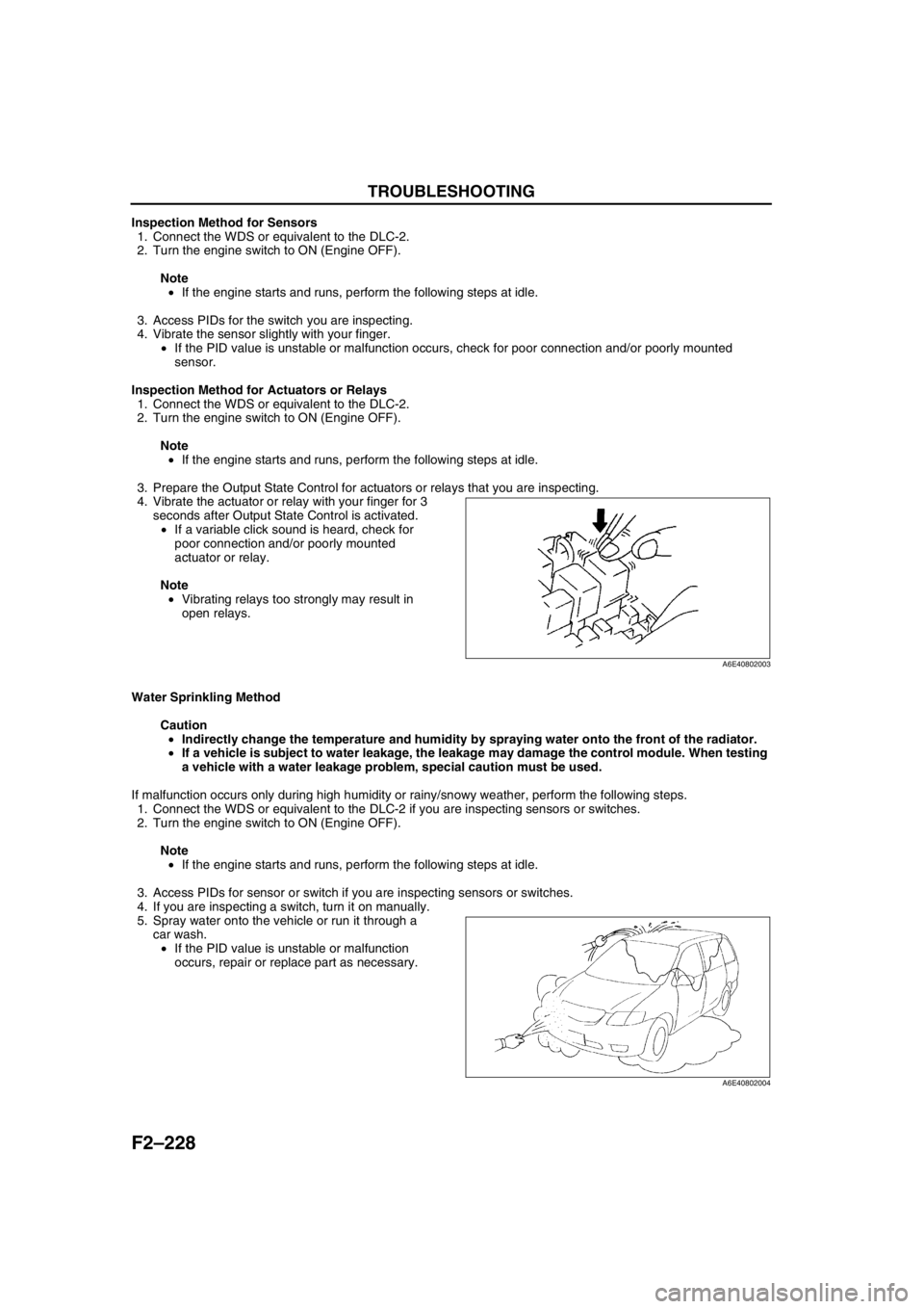
4. Vibrate the actuator or relay with your finger for 3
seconds after Output State Control is activated.
•If a variable click sound is heard, check for
poor connection and/or poorly mounted
actuator or relay.
Note
•Vibrating relays too strongly may result in
open relays.
Water Sprinkling Method
Caution
•Indirectly change the temperature and humidity by spraying water onto the front of the radiator.
•If a vehicle is subject to water leakage, the leakage may damage the control module. When testing
a vehicle with a water leakage problem, special caution must be used.
If malfunction occurs only during high humidity or rainy/snowy weather, perform the following steps.
1. Connect the WDS or equivalent to the DLC-2 if you are inspecting sensors or switches.
2. Turn the engine switch to ON (Engine OFF).
Note
•If the engine starts and runs, perform the following steps at idle.
3. Access PIDs for sensor or switch if you are inspecting sensors or switches.
4. If you are inspecting a switch, turn it on manually.
5. Spray water onto the vehicle or run it through a
car wash.
•If the PID value is unstable or malfunction
occurs, repair or replace part as necessary.
End Of Sie
A6E40802003
A6E40802004
Page 390 of 909
CHARGING SYSTEM
G–7
G
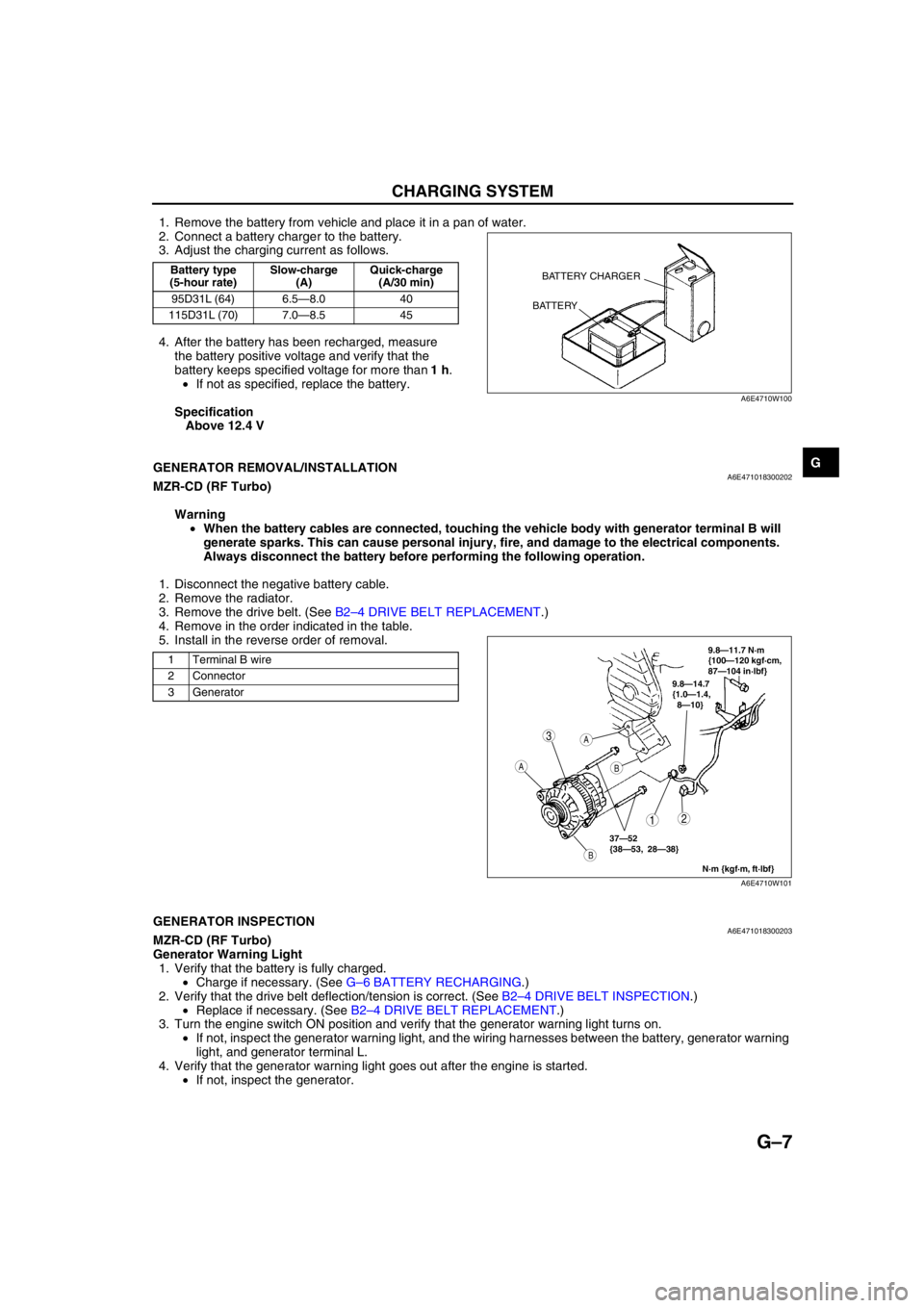
1. Remove the battery from vehicle and place it in a pan of water.
2. Connect a battery charger to the battery.
3. Adjust the charging current as follows.
4. After the battery has been recharged, measure
the battery positive voltage and verify that the
battery keeps specified voltage for more than 1 h.
•If not as specified, replace the battery.
Specification
Above 12.4 V
End Of Sie
GENERATOR REMOVAL/INSTALLATIONA6E471018300202MZR-CD (RF Turbo)
Warning
•When the battery cables are connected, touching the vehicle body with generator terminal B will
generate sparks. This can cause personal injury, fire, and damage to the electrical components.
Always disconnect the battery before performing the following operation.
1. Disconnect the negative battery cable.
2. Remove the radiator.
3. Remove the drive belt. (See B2–4 DRIVE BELT REPLACEMENT.)
4. Remove in the order indicated in the table.
5. Install in the reverse order of removal.
End Of SieGENERATOR INSPECTIONA6E471018300203MZR-CD (RF Turbo)
Generator Warning Light
1. Verify that the battery is fully charged.
•Charge if necessary. (See G–6 BATTERY RECHARGING.)
2. Verify that the drive belt deflection/tension is correct. (See B2–4 DRIVE BELT INSPECTION.)
•Replace if necessary. (See B2–4 DRIVE BELT REPLACEMENT.)
3. Turn the engine switch ON position and verify that the generator warning light turns on.
•If not, inspect the generator warning light, and the wiring harnesses between the battery, generator warning
light, and generator terminal L.
4. Verify that the generator warning light goes out after the engine is started.
•If not, inspect the generator.
Battery type
(5-hour rate)Slow-charge
(A)Quick-charge
(A/30 min)
95D31L (64) 6.5—8.0 40
115D31L (70) 7.0—8.5 45BATTERY CHARGER
BATTERY
A6E4710W100
1 Terminal B wire
2 Connector
3 Generator
3
12
A
B
A
B
9.8—14.7
{1.0—1.4,
8—10}
N·m {kgf·m, ft·lbf}
37—52
{38—53, 28—38}
9.8—11.7 N·m
{100—120 kgf·cm,
87—104 in·lbf}
A6E4710W101
Page 391 of 909
G–8
CHARGING SYSTEM
Generator
Voltage
1. Verify that the battery is fully charged.
•Charge if necessary. (See G–6 BATTERY RECHARGING.)
2. Inspect the drive belt deflection/tension.
(See B2–4 DRIVE BELT INSPECTION.)
•Replace if necessary. (See B2–4 DRIVE BELT REPLACEMENT.)
3. Turn off all electrical loads.
4. Turn the engine switch to start the engine and verify that the generator rotates smoothly without any noise
while the engine is running.
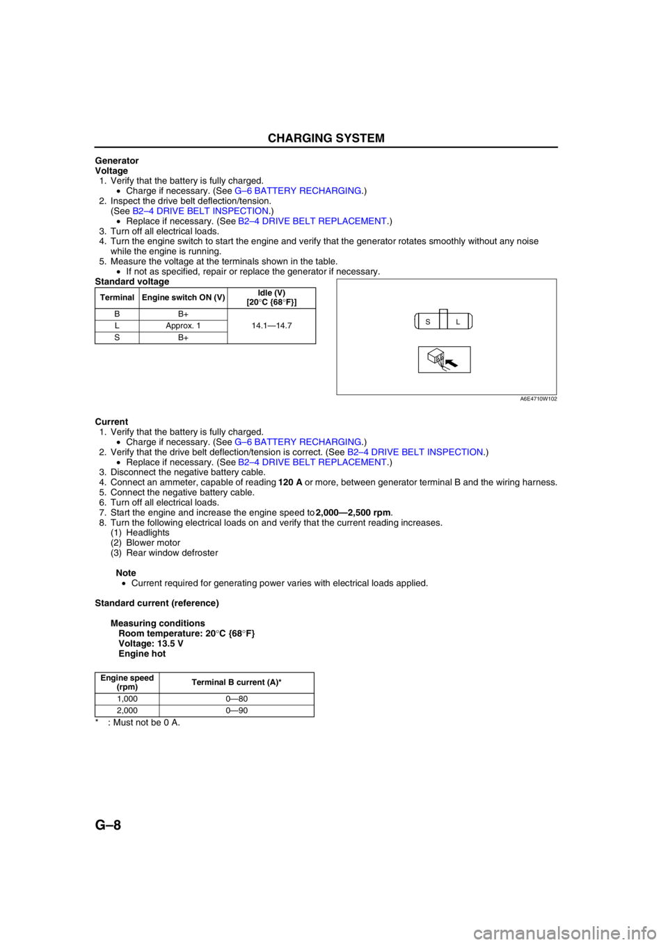
5. Measure the voltage at the terminals shown in the table.
•If not as specified, repair or replace the generator if necessary.
Standard voltage
Current
1. Verify that the battery is fully charged.
•Charge if necessary. (See G–6 BATTERY RECHARGING.)
2. Verify that the drive belt deflection/tension is correct. (See B2–4 DRIVE BELT INSPECTION.)
•Replace if necessary. (See B2–4 DRIVE BELT REPLACEMENT.)
3. Disconnect the negative battery cable.
4. Connect an ammeter, capable of reading 120 A or more, between generator terminal B and the wiring harness.
5. Connect the negative battery cable.
6. Turn off all electrical loads.
7. Start the engine and increase the engine speed to 2,000—2,500 rpm.
8. Turn the following electrical loads on and verify that the current reading increases.
(1) Headlights
(2) Blower motor
(3) Rear window defroster
Note
•Current required for generating power varies with electrical loads applied.
Standard current (reference)
Measuring conditions
Room temperature: 20°C {68°F}
Voltage: 13.5 V
Engine hot
* : Must not be 0 A.
End Of Sie
Terminal Engine switch ON (V)Idle (V)
[20°C {68°F}]
BB+
14.1—14.7 LApprox. 1
SB+
SL
A6E4710W102
Engine speed
(rpm)Terminal B current (A)*
1,000 0—80
2,000 0—90
Page 408 of 909
J2–6
MANUAL TRANSAXLE
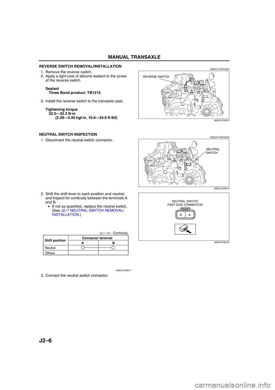
REVERSE SWITCH REMOVAL/INSTALLATIONA6E5212190102021. Remove the reverse switch.
2. Apply a light coat of silicone sealant to the screw
of the reverse switch.
Sealant
Three Bond product: TB1215
3. Install the reverse switch to the transaxle case.
Tightening torque
22.5—33.3 N·m
{2.29—3.40 kgf·m, 16.6—24.6 ft·lbf}
End Of Sie
NEUTRAL SWITCH INSPECTIONA6E5212190102031. Disconnect the neutral switch connector.
2. Shift the shift lever to each position and neutral,
and inspect for continuity between the terminals A
and B.
•If not as specified, replace the neutral switch.
(See J2–7 NEUTRAL SWITCH REMOVAL/
INSTALLATION.)
3. Connect the neutral switch connector.
End Of Sie
REVERSE SWITCH
A6E5212W012
NEUTRAL
SWITCH
A6E5212W015
BA NEUTRAL SWITCH
PART SIDE CONNENTOR
A6E5212W016Shift positionConnector terminal
AB:
Continuity
Neutral
Others
A6E5212W017