light MAZDA 6 2002 Suplement Service Manual
[x] Cancel search | Manufacturer: MAZDA, Model Year: 2002, Model line: 6, Model: MAZDA 6 2002Pages: 909, PDF Size: 17.16 MB
Page 409 of 909
MANUAL TRANSAXLE
J2–7
J2
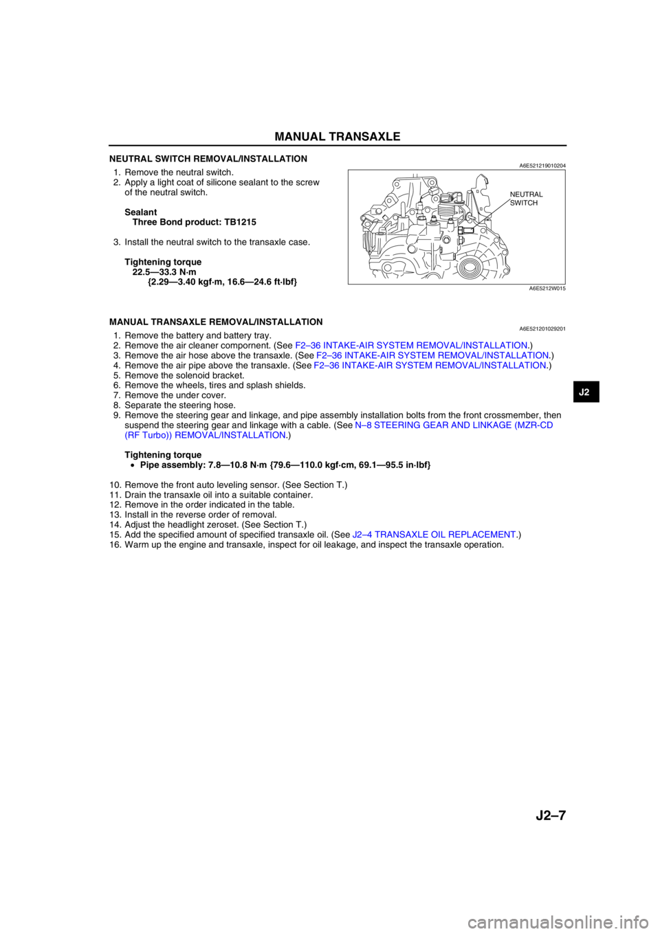
NEUTRAL SWITCH REMOVAL/INSTALLATIONA6E5212190102041. Remove the neutral switch.
2. Apply a light coat of silicone sealant to the screw
of the neutral switch.
Sealant
Three Bond product: TB1215
3. Install the neutral switch to the transaxle case.
Tightening torque
22.5—33.3 N·m
{2.29—3.40 kgf·m, 16.6—24.6 ft·lbf}
End Of Sie
MANUAL TRANSAXLE REMOVAL/INSTALLATIONA6E5212010292011. Remove the battery and battery tray.
2. Remove the air cleaner compornent. (See F2–36 INTAKE-AIR SYSTEM REMOVAL/INSTALLATION.)
3. Remove the air hose above the transaxle. (See F2–36 INTAKE-AIR SYSTEM REMOVAL/INSTALLATION.)
4. Remove the air pipe above the transaxle. (See F2–36 INTAKE-AIR SYSTEM REMOVAL/INSTALLATION.)
5. Remove the solenoid bracket.
6. Remove the wheels, tires and splash shields.
7. Remove the under cover.
8. Separate the steering hose.
9. Remove the steering gear and linkage, and pipe assembly installation bolts from the front crossmember, then
suspend the steering gear and linkage with a cable. (See N–8 STEERING GEAR AND LINKAGE (MZR-CD
(RF Turbo)) REMOVAL/INSTALLATION.)
Tightening torque
•Pipe assembly: 7.8—10.8 N·m {79.6—110.0 kgf·cm, 69.1—95.5 in·lbf}
10. Remove the front auto leveling sensor. (See Section T.)
11. Drain the transaxle oil into a suitable container.
12. Remove in the order indicated in the table.
13. Install in the reverse order of removal.
14. Adjust the headlight zeroset. (See Section T.)
15. Add the specified amount of specified transaxle oil. (See J2–4 TRANSAXLE OIL REPLACEMENT.)
16. Warm up the engine and transaxle, inspect for oil leakage, and inspect the transaxle operation.
NEUTRAL
SWITCH
A6E5212W015
Page 412 of 909

J2–10
MANUAL TRANSAXLE
Manual Transaxle Installation Note
1. Set the transaxle on a jack and lift into place.
2. Install the transaxle mounting bolts.
3. Install the stud of the No.4 engine mount.
Tightening torque
27.4—40.2 N·m
{2.80—4.09 kgf·m, 20.2—29.6 ft·lbf}
4. Tighten the SST (49 E017 5A0)so that the engine
is located at the specified position.
No.4 Engine Mount Installation Note
1. Verify that the No.4 engine mount rubber is installed as shown.
2. Lightly tighten the bolt A and B.
3. Align the contacted area to front frame of the bolt C to the front frame.
4. Tighten the bolt A, then bolt B.
5. Tighten the bolt C, then bolt D.
Tightening torque
A,B,C,D: 58.8—80.4 N·m
{6.00—8.19 kgf·m, 43.4—59.2 ft·lbf}
6. Verify that the No.4 engine mount bracket is
installed as shown.
7. Lightly tighten the bolt E.
8. Set the transaxle on a garage jack and lift it.
9. Align the hole of the No.4 engine mount bracket
with the stud bolts of transaxle.
10. Lightly tighten the nut F, G and bolt H.
11. Tighten the nut F, G in order of F→G, then bolt H.
A6E5212W022
STUD
A6E5212W020
D
H
C
FB
A
GE
A6E5212W024
TRANSAXLE
GARAGE JACK
A6E5212W023
Page 413 of 909
MANUAL TRANSAXLE
J2–11
J2
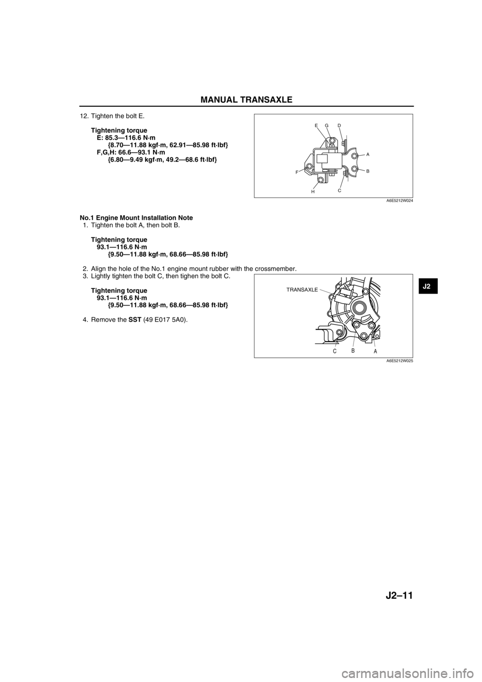
12. Tighten the bolt E.
Tightening torque
E: 85.3—116.6 N·m
{8.70—11.88 kgf·m, 62.91—85.98 ft·lbf}
F,G,H: 66.6—93.1 N·m
{6.80—9.49 kgf·m, 49.2—68.6 ft·lbf}
No.1 Engine Mount Installation Note
1. Tighten the bolt A, then bolt B.
Tightening torque
93.1—116.6 N·m
{9.50—11.88 kgf·m, 68.66—85.98 ft·lbf}
2. Align the hole of the No.1 engine mount rubber with the crossmember.
3. Lightly tighten the bolt C, then tighen the bolt C.
Tightening torque
93.1—116.6 N·m
{9.50—11.88 kgf·m, 68.66—85.98 ft·lbf}
4. Remove the SST (49 E017 5A0).
End Of Sie
D
H
C
FB
A
GE
A6E5212W024
TRANSAXLE
CB
A
A6E5212W025
Page 417 of 909
K2–2
AUTOMATIC TRANSAXLE ON-BOARD
DIAGNOSTIC FUNCTION .......................... K2-123
AFTER REPAIR PROCEDURE ..................... K2-124
DTC TABLE ................................................... K2-126
DTC P0705 .................................................... K2-127
DTC P0706 .................................................... K2-129
DTC P0711 .................................................... K2-132
DTC P0712 .................................................... K2-133
DTC P0713 .................................................... K2-135
DTC P0715 .................................................... K2-137
DTC P0720 .................................................... K2-139
DTC P0740 .................................................... K2-142
DTC P0743 .................................................... K2-144
DTC P0748 .................................................... K2-146
DTC P0751 .................................................... K2-149
DTC P0752 .................................................... K2-150
DTC P0753 .................................................... K2-151
DTC P0756 .................................................... K2-153
DTC P0757 .................................................... K2-154
DTC P0758 .................................................... K2-155
DTC P0761 .................................................... K2-158
DTC P0762 .................................................... K2-159
DTC P0763 .................................................... K2-160
DTC P0768 .................................................... K2-163
DTC P0773 .................................................... K2-166
DTC P0778 .................................................... K2-169
DTC P0791 .................................................... K2-172
DTC P0798 .................................................... K2-175
DTC P1710 .................................................... K2-178
PID/DATA MONITOR INSPECTION.............. K2-180
TROUBLESHOOTING...................................... K2-182
FOREWORD .................................................. K2-182
AUTOMATIC TRANSAXLE BASIC
INSPECTION .............................................. K2-182
AUTOMATIC TRANSAXLE SYMPTOM
TROUBLESHOOTING ................................ K2-183
NO.1 VEHICLE DOES NOT MOVE IN
D RANGE, OR IN R POSITION .................. K2-188
NO.2 VEHICLE MOVES IN N POSITION ...... K2-188
NO.3 VEHICLE MOVES IN P POSITION,
OR PARKING GEAR DOES NOT
DISENGAGE WHEN P IS DISENGAGED .. K2-189
NO.4 EXCESSIVE CREEP ............................ K2-189
NO.5 NO CREEP AT ALL .............................. K2-189
NO.6 LOW MAXIMUM SPEED AND
POOR ACCELERATION............................. K2-190
NO.7 NO SHIFTING....................................... K2-191
NO.8 DOES NOT SHIFT TO FIFTH
GEAR (5GR) ............................................... K2-192
NO.9 ABNORMAL SHIFTING ........................ K2-193
NO.10 FREQUENT SHIFTING ...................... K2-193
NO.11 SHIFT POINT IS HIGH OR LOW ....... K2-194
NO.12 TORQUE CONVERTER
CLUTCH (TCC) NON-OPERATION ........... K2-194
NO.13 NO KICKDOWN.................................. K2-195
NO.14 ENGINE FLARES UP OR
SLIPS WHEN UPSHIFTING OR
DOWNSHIFTING ........................................ K2-195
NO.15 ENGINE FLARES UP OR
SLIPS WHEN ACCELERATING VEHICLE. K2-196
NO.16 JUDDER UPON TORQUE
CONVERTER CLUTCH (TCC)
OPERATION ............................................... K2-196NO.17 EXCESSIVE SHIFT SHOCK
FROM N TO D OR N TO R
POSITION/RANGE ..................................... K2-196
NO.18 EXCESSIVE SHIFT SHOCK IS
GIVEN WHEN UPSHIFTING AND
DOWNSHIFTING ........................................ K2-197
NO.19 EXCESSIVE SHIFT SHOCK
ON TORQUE CONVERTER CLUTCH
(TCC) .......................................................... K2-197
NO.20 NOISE OCCURS AT IDLE WHEN
VEHICLE IS STOPPED IN ALL
POSITIONS/RANGES ................................ K2-198
NO.21 NOISE OCCURS AT IDLE
WHEN VEHICLE IS STOPPED IN
D RANGE, OR IN R POSITION .................. K2-198
NO.22 NO ENGINE BRAKING IN 1GR
POSITION OF M RANGE ........................... K2-198
NO.23 TRANSAXLE OVERHEATS ............... K2-199
NO.24 ENGINE STALLS WHEN SHIFTED
TO D RANGE, OR IN R POSITION ............ K2-199
NO.25 ENGINE STALLS WHEN DRIVING
AT SLOW SPEED OR STOPPING ............. K2-200
NO.26 STARTER DOES NOT WORK ........... K2-200
NO.27 GEAR POSITION INDICATOR
LIGHT DOES NOT ILLUMINATE IN
M RANGE ................................................... K2-200
NO.28 GEAR POSITION INDICATOR
LIGHT ILLUMINATES IN D RANGE
OR IN P, N, R POSITIONS ......................... K2-201
NO.29 DOES NOT SHIFT UP IN M RANGE . K2-201
NO.30 DOES NOT SHIFT DOWN IN
M RANGE ................................................... K2-201
Page 418 of 909

OUTLINE
K2–3
K2
FEATURESA6E570201030201ATX
Improved marketability
•New JA5AX-EL automatic transaxle for 4WD is used with on L3 engine.
Improved shift quality
•Five speed automatic transaxle has been adopted.
•The feedback control system has been adopted.
•The centrifugal balance clutch chambers have been adopted.
•A plate-type clutch pack replaces the band brake in the 2-4 brake.
High efficiency, compactness, and light weight
•Miniature trochoid gear type oil pump with torque converter direct drive has been adopted.
End Of Sie
SPECIFICATIONSA6E570201030202
OUTLINE
ItemNew Mazda6 (GY) Current MPV (LW)
–For General
(R.H.D.)
specs.Except for
General
(R.H.D.)
specs.
Transaxle type JA5AX-EL JA5A-EL
Gear ratio1GR 3.801
2GR 2.131
3GR 1.364
4GR 0.935
5GR (O/D) 0.685
Reverse 2.970
Final gear ratio 3.491 3.290 3.491
ATFType
ATF M-III or equivalent (e.g. Dexron
®III)
Capacity (approximate quantity)
(L {US qt, Imp qt})8.3 {8.8, 7.3} 9.7 {10.3, 8.5}
Torque converter stall torque ratio 1.86:1
Hydraulic system (Number of
drive/driven plates)Low clutch 6/6 7/7
2-4 brake 3/4
High clutch 5/5
Direct clutch 3/5 4/4
Reverse clutch 2/2
Low and reverse brake 6/5
Band servo (mm {in})Reduction accumulator piston outer
dia./reduction band servo piston
outer dia.49.66/57.64
Number of front planetary gear
teethRing gear 74
Sun gear 34
Pinion gear 20
Number of rear planetary gear
teethRing gear 75
Sun gear 42
Pinion gear 17
Number of reduction planetary
gear teethRing gear 85
Sun gear 31
Pinion gear 27
Number of output gear teeth 41
Number of idler gear teeth 47
Number of reduction gear teeth 22 23 22
Number of ring gear teeth 67 66 67
Transfer oilTypeSAE 80W-90
API Service GL-5–
Capacity (approximate quantity)
(L {US qt, Imp qt})0.62 {0.66, 0.55}–
Page 423 of 909
K2–8
AUTOMATIC TRANSAXLE
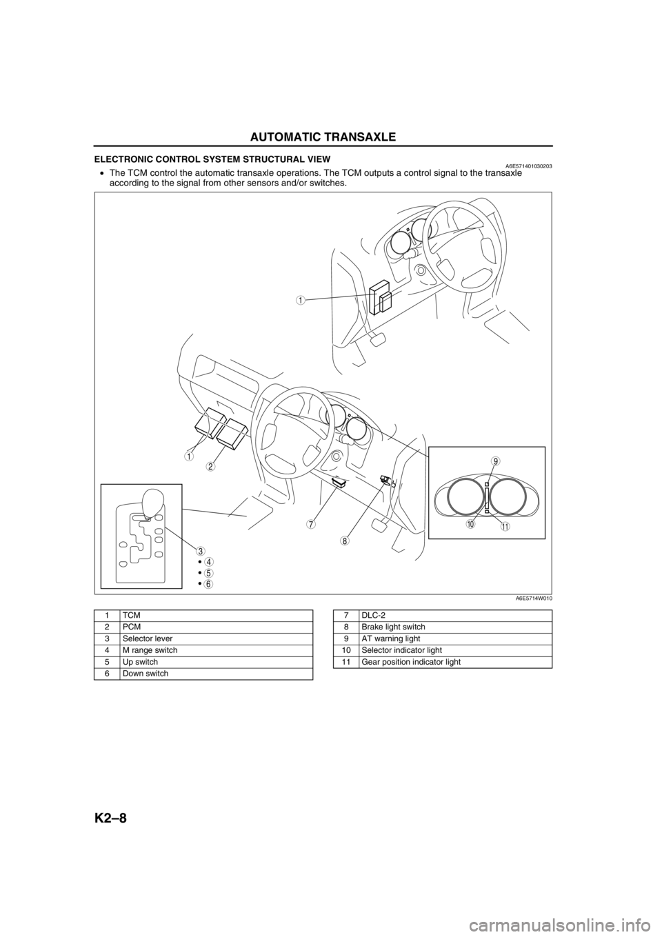
ELECTRONIC CONTROL SYSTEM STRUCTURAL VIEWA6E571401030203•The TCM control the automatic transaxle operations. The TCM outputs a control signal to the transaxle
according to the signal from other sensors and/or switches.
.
9
8
7
5
4
3
1
2
1011
6
1
A6E5714W010
1TCM
2PCM
3Selector lever
4 M range switch
5 Up switch
6 Down switch7DLC-2
8 Brake light switch
9 AT warning light
10 Selector indicator light
11 Gear position indicator light
Page 426 of 909
AUTOMATIC TRANSAXLE
K2–11
K2
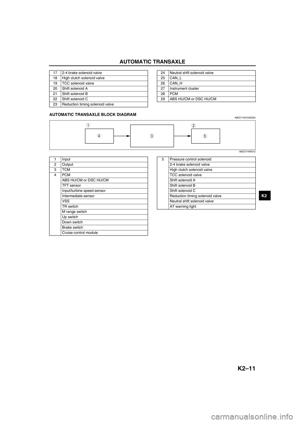
End Of SieAUTOMATIC TRANSAXLE BLOCK DIAGRAMA6E571401030205
.
17 2-4 brake solenoid valve
18 High clutch solenoid valve
19 TCC solenoid valve
20 Shift solenoid A
21 Shift solenoid B
22 Shift solenoid C
23 Reduction timing solenoid valve24 Neutral shift solenoid valve
25 CAN_L
26 CAN_H
27 Instrument cluster
28 PCM
29 ABS HU/CM or DSC HU/CM
543
12
A6E5714W012
1 Input
2Output
3TCM
4PCM
ABS HU/CM or DSC HU/CM
TFT sensor
Input/turbine speed sensor
Intermediate sensor
VSS
TR switch
M range switch
Up switch
Down switch
Brake switch
Cruise control module5 Pressure control solenoid
2-4 brake solenoid valve
High clutch solenoid valve
TCC solenoid valve
Shift solenoid A
Shift solenoid B
Shift solenoid C
Reduction timing solenoid valve
Neutral shift solenoid valve
AT warning light
Page 428 of 909
AUTOMATIC TRANSAXLE
K2–13
K2
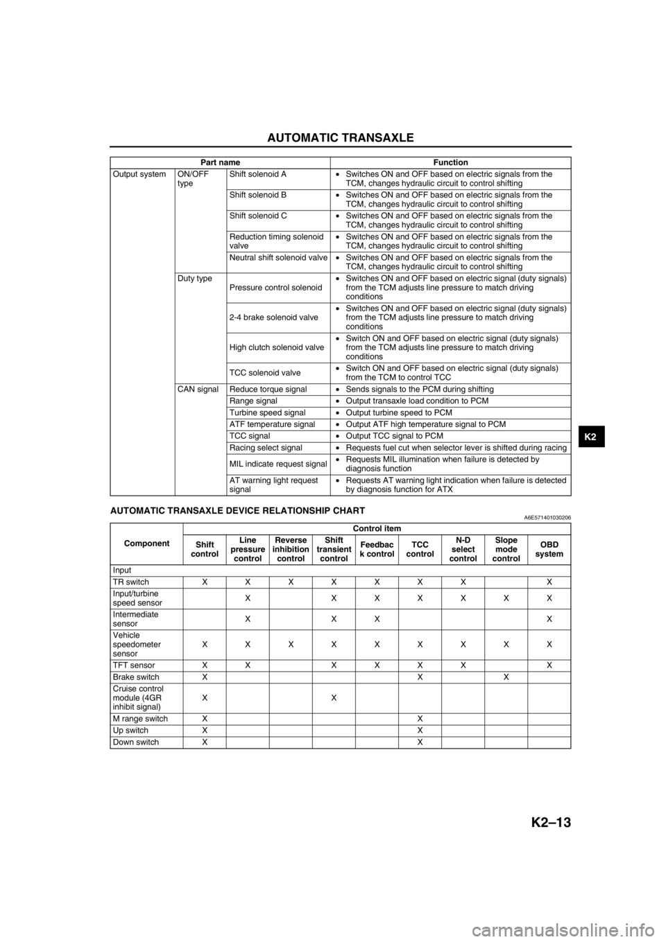
End Of SieAUTOMATIC TRANSAXLE DEVICE RELATIONSHIP CHARTA6E571401030206
Output system ON/OFF
typeShift solenoid A•Switches ON and OFF based on electric signals from the
TCM, changes hydraulic circuit to control shifting
Shift solenoid B•Switches ON and OFF based on electric signals from the
TCM, changes hydraulic circuit to control shifting
Shift solenoid C•Switches ON and OFF based on electric signals from the
TCM, changes hydraulic circuit to control shifting
Reduction timing solenoid
valve•Switches ON and OFF based on electric signals from the
TCM, changes hydraulic circuit to control shifting
Neutral shift solenoid valve•Switches ON and OFF based on electric signals from the
TCM, changes hydraulic circuit to control shifting
Duty type
Pressure control solenoid•Switches ON and OFF based on electric signal (duty signals)
from the TCM adjusts line pressure to match driving
conditions
2-4 brake solenoid valve•Switches ON and OFF based on electric signal (duty signals)
from the TCM adjusts line pressure to match driving
conditions
High clutch solenoid valve•Switch ON and OFF based on electric signal (duty signals)
from the TCM adjusts line pressure to match driving
conditions
TCC solenoid valve•Switch ON and OFF based on electric signal (duty signals)
from the TCM to control TCC
CAN signal Reduce torque signal•Sends signals to the PCM during shifting
Range signal•Output transaxle load condition to PCM
Turbine speed signal•Output turbine speed to PCM
ATF temperature signal•Output ATF high temperature signal to PCM
TCC signal•Output TCC signal to PCM
Racing select signal•Requests fuel cut when selector lever is shifted during racing
MIL indicate request signal•Requests MIL illumination when failure is detected by
diagnosis function
AT warning light request
signal•Requests AT warning light indication when failure is detected
by diagnosis function for ATX Part name Function
ComponentControl item
Shift
controlLine
pressure
controlReverse
inhibition
controlShift
transient
controlFeedbac
k controlTCC
controlN-D
select
controlSlope
mode
controlOBD
system
Input
TR switch XXXXXXX X
Input/turbine
speed sensorX XXXXXX
Intermediate
sensorXXX X
Vehicle
speedometer
sensorXXXXXXXXX
TFT sensor XX XXXX X
Brake switch X X X
Cruise control
module (4GR
inhibit signal)XX
M range switch X X
Up switch X X
Down switch X X
Page 430 of 909
AUTOMATIC TRANSAXLE
K2–15
K2
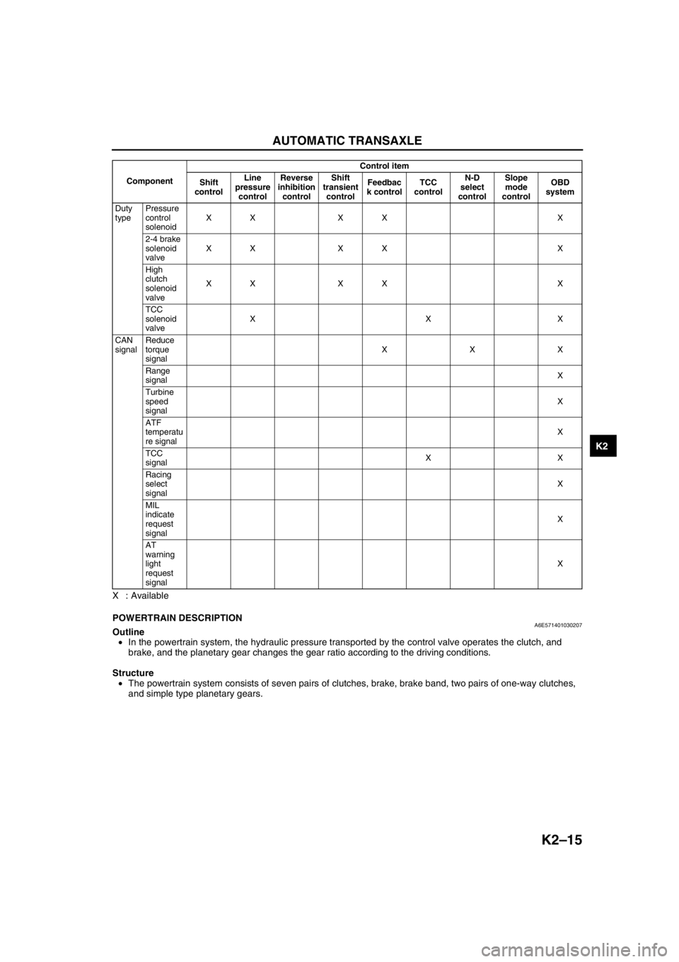
X : Available
End Of SiePOWERTRAIN DESCRIPTIONA6E571401030207Outline
•In the powertrain system, the hydraulic pressure transported by the control valve operates the clutch, and
brake, and the planetary gear changes the gear ratio according to the driving conditions.
Structure
•The powertrain system consists of seven pairs of clutches, brake, brake band, two pairs of one-way clutches,
and simple type planetary gears.
Duty
typePressure
control
solenoidXX XX X
2-4 brake
solenoid
valveXX XX X
High
clutch
solenoid
valveXX XX X
TCC
solenoid
valveXXX
CAN
signalReduce
torque
signalXXX
Range
signalX
Turbine
speed
signalX
ATF
temperatu
re signalX
TCC
signalXX
Racing
select
signalX
MIL
indicate
request
signalX
AT
warning
light
request
signalX ComponentControl item
Shift
controlLine
pressure
controlReverse
inhibition
controlShift
transient
controlFeedbac
k controlTCC
controlN-D
select
controlSlope
mode
controlOBD
system
Page 456 of 909
AUTOMATIC TRANSAXLE
K2–41
K2
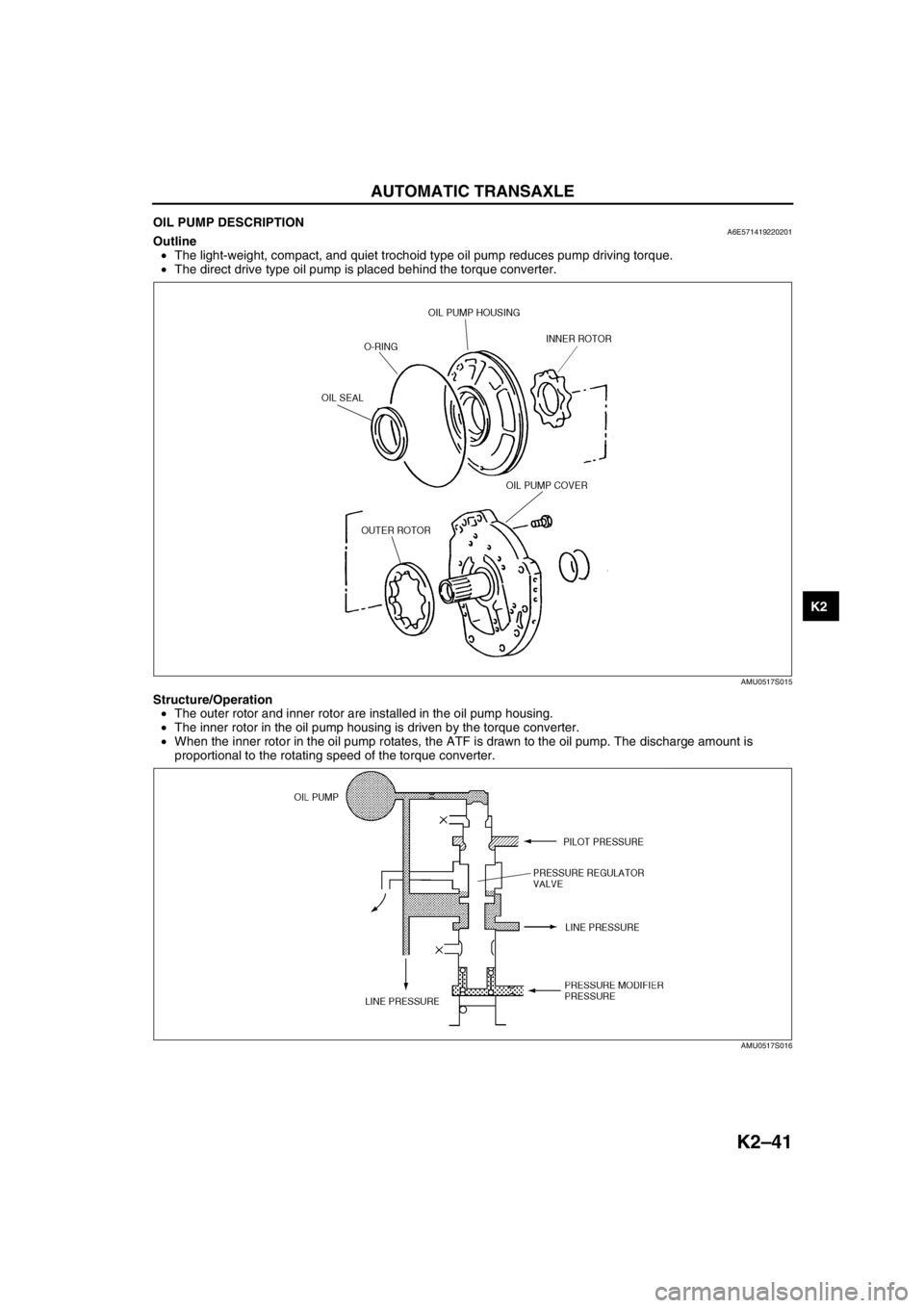
OIL PUMP DESCRIPTIONA6E571419220201Outline
•The light-weight, compact, and quiet trochoid type oil pump reduces pump driving torque.
•The direct drive type oil pump is placed behind the torque converter.
Structure/Operation
•The outer rotor and inner rotor are installed in the oil pump housing.
•The inner rotor in the oil pump housing is driven by the torque converter.
•When the inner rotor in the oil pump rotates, the ATF is drawn to the oil pump. The discharge amount is
proportional to the rotating speed of the torque converter.
End Of Sie
AMU0517S015
AMU0517S016