light MAZDA 6 2002 Suplement Repair Manual
[x] Cancel search | Manufacturer: MAZDA, Model Year: 2002, Model line: 6, Model: MAZDA 6 2002Pages: 909, PDF Size: 17.16 MB
Page 465 of 909

K2–50
AUTOMATIC TRANSAXLE
CONTROLLER AREA NETWORK (CAN) DESCRIPTIONA6E571418901201Outline
•The TCM transmits/receives information using the CAN system. See Section T for detailed information
regarding the CAN system.
Structure/Operation
•The PCM inputs throttle opening angle, engine speed, engine torque, engine coolant temperature. to the TCM.
•The TCM operates shift and TCC controls based on the throttle opening angle, and controls line pressure and
other based on the throttle opening angle and the engine torque.
•The TCM outputs reduce torque signal, range signal, turbine speed, ATF temperature signal, and TCC signal to
the PCM.
•If there is an open or short circuit in the CAN wiring, the system determines that the CAN is abnormal and
switches to fail-safe mode.
Input
•Throttle position
•Engine torque (without torque down)
•Engine torque (with torque down)
•Engine torque (loss torque)
•Torque reduction request
•ECT
•Engine speed
•Buttery reconnection
Output
•Range position
•Turbine speed
•ATF temperature
•TCC
•Racing select
•Gear position
•Desired torque
•Desired gear position
•Upper torque limit
•Traveled distance
•MIL indicate request
•AT warning light indicate request
End Of Sie
Page 467 of 909
K2–52
AUTOMATIC TRANSAXLE
Operation
Range determination
•Each range is determined by operating the selector lever, and switching ON/OFF the switch in the TR switch
internal circuit. The present range is detected according to the ON/OFF signal of the switch.
•The following switches are built into the TR switch, and determine each range when the switch is on.
P position switch
R position switch
N position switch
D range switch
End Of Sie
MANUAL MODE SHIFT CONTROL DESCRIPTIONA6E571418901204Outline
Features
•The manual mode shift control is activated by moving the selector lever from the D to M range position (selector
lever is shifted over toward front passenger side).
•Manual mode shift control with a manual shifting system allowing selection of gear positions by manual
operation of the selector lever forward (-) and back (+) has been adopted. Moreover, engine braking for all
gears in manual mode according to the gear ratio is available.
— Shifting between 1GR and 2GR when the vehicle is stopped is possible.
— When shifting from the D to M range while driving, the same gear position is maintained.
— Consecutive shifting in the M range has been adopted. When shifting down from M range 4GR or 3GR, one
gear can be skipped over by rapidly tapping the selector lever two times in the down-shift (-) direction.
•Selector lever position and gear position indicator lights, built into the instrument cluster, have been adopted.
— The selector indicator light includes a selector lever position indicator that displays selector lever positions
and, a gear position indicator light that displays gear positions.
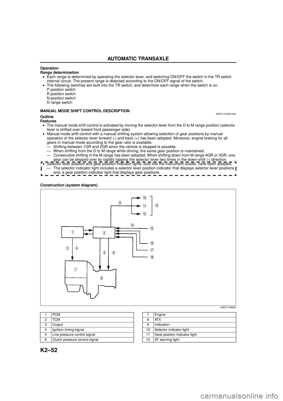
Construction (system diagram)
.
9
8
7
5
43
12
10
18
17
15
16
14
1311
12
6
A6E5714W065
1PCM
2TCM
3Output
4 Ignition timing signal
5 Line pressure control signal
6 Clutch pressure control signal7Engine
8ATX
9 Indication
10 Selector indicator light
11 Gear position indicator light
12 AT warning light
Page 468 of 909

AUTOMATIC TRANSAXLE
K2–53
K2
Operation
Manual mode shift
•When the selector lever is shifted over from the D to M range position, the M range switch in the selector lever
component turns on, sending a manual mode command signal to the PCM which activates the manual mode
shift control.
•When in manual mode and the selector lever is operated in the back (+) direction, the up switch in the selector
lever component is turned on and an up-shift command signal is inputted to the PCM.
—The PCM, triggered by the up-shift command signal, carries out shifting by outputting an operation signal to
the shift solenoid if the ATF temperature is not low (for 3GR only), vehicle speed is higher than the set
speed and the gear position is 3GR or lower.
•Conversely, when the selector lever is operated in the forward (-) direction, the down switch in the selector lever
component turns on, and a down-shift command signal is inputted to the PCM.
—The PCM, triggered by the down-shift command signal, carries out shifting by outputting an operation
signal to the shift solenoid if the vehicle speed is less than the set speed and the gear position is 2GR or
above.
•The PCM utilizes a specialized M range automatic shift diagram when down shifting. This restriction of manual
downshifting is carried out to reduce load on the ATX and prevent engine over-revving.
13 Instrument cluster
14 Input15 Selector lever component
-M range switch
-Up switch
-Down switch
16 TR switch
17 ABS HU/CM or DSC HU/CM
18 TFT sensor
Condition Shift control Note
2GR→3GR up-shift command
at low speed•To reduce load on the ATX, upshifting is
inhibited until vehicle reaches speed
possible for upshifting
— 3GR→4GR up-shift command
at low speed
3GR→4GR up-shift command,
low ATF temperature•To reduce load on the ATX, upshifting to
4GR is inhibited
4GR→3GR down-shift
command, above set speed•To prevent engine over-rev, downshifting is
inhibited until vehicle reaches speed
possible for downshifting•Selector indicator “M” light and gear
position indicator light flash to alert
driver
3GR→2GR down-shift
command, above set speed
2GR→1GR down-shift
command, above set speed
In 4GR deceleration, speed
goes below coast-down set
speed (deceleration down-
shift)•To assure drive stability, automatically
downshifts from 4GR to 3GR
— In 3GR deceleration, speed
goes below coast-down set
speed (deceleration down-
shift)•To assure drive stability, automatically
downshifts from 3GR to 1GR
In 2GR deceleration, speed
goes below coast-down set
speed (deceleration down-
shift)•To assure driving stability, automatically
downshifts from 2GR to 1GR
Page 479 of 909
K2–64
AUTOMATIC TRANSAXLE
ON-BOARD DIAGNOSTIC (OBD) SYSTEM DESCRIPTIONA6E571418901210•The OBD system has the following functions:
—Failure detection function: detects failure of the input/output devices and system components of the ATX.
—Memory function: stores the DTC when a failure is detected.
—Fail-safe function: fixes the output device function and input value of the sensors/switches to ensure
minimum vehicle drivability when a failure is detected.
—PID data monitoring function: monitors the input/output signal and calculated value of the TCM and sends
the monitoring data to the scan tool.
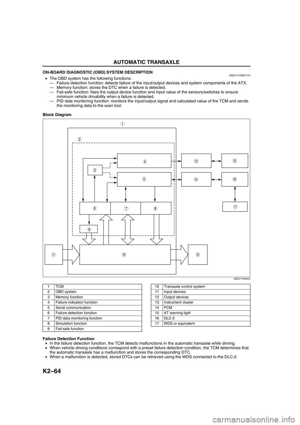
Block Diagram
.
Failure Detection Function
•In the failure detection function, the TCM detects malfunctions in the automatic transaxle while driving.
•When vehicle driving conditions correspond with a preset failure detection condition, the TCM determines that
the automatic transaxle has a malfunction and stores the corresponding DTC.
•When a malfunction is detected, stored DTCs can be retrieved using the WDS connected to the DLC-2.
9
87
5
4
3
1
2
10
17
15
1614
13
1112
6
A6E5714W023
1TCM
2 OBD system
3 Memory function
4 Failure indication function
5 Serial communication
6 Failure detection function
7 PID data monitoring function
8 Simulation function
9 Fail-safe function10 Transaxle control system
11 Input devices
12 Output devices
13 Instrument cluster
14 PCM
15 AT warning light
16 DLC-2
17 WDS or equivalent
Page 480 of 909

AUTOMATIC TRANSAXLE
K2–65
K2
Memory Function
•The memory function stores failure information detected in the failure detection function. Once failure
information is stored, the memory will not be cleared even when the ignition switch is turned off (LOCK
position) or the malfunction is repaired.
•The stored memory (failure information) can be cleared by using the WDS or disconnecting the negative
battery cable.
Failure Indication Function
•The failure indication function illuminates the AT warning lights when the failure detection function determines
there is a malfunction.
DTC Table
X : Available
CCM:Continuous monitor
Fail-safe Function
•In the fail-safe function, minimum vehicle drivability is obtained by changing the signals that are determined as
malfunctions by the failure detection function to the preset values, and limiting the TCM control.
DTC No. On-board diagnostic function MILAT warning
light
indicationDCMonitor
itemMemory
function
P0705 TR switch circuit malfunction (Power short circuit) X X 2 CCM X
P0706 TR switch circuit malfunction (Open/ground short circuit) X X 2 CCM X
P0711 TFT sensor malfunction (Stuck) X–2 CCM X
P0712 TFT sensor circuit malfunction (Short circuit) X X 2 CCM X
P0713 TFT sensor circuit malfunction (Open circuit) X X 2 CCM X
P0715 Input/turbine speed sensor circuit malfunction X X 2 CCM X
P0720 Vehicle speedometer sensor circuit malfunction X X 2 CCM X
P0740 TCC system X–2 CCM X
P0743 TCC solenoid valve malfunction (Open/short) X X 1 CCM X
P0748 Pressure control solenoid malfunction (Open/short)–X–CCM X
P0751 Shift solenoid A malfunction (Stuck off) X–2 CCM X
P0752 Shift solenoid A malfunction (Stuck on) X–2 CCM X
P0753 Shift solenoid A malfunction (Open/short) X X 1 CCM X
P0756 Shift solenoid B malfunction (Stuck off) X–2 CCM X
P0757 Shift solenoid B malfunction (Stuck on) X–2 CCM X
P0758 Shift solenoid B malfunction (Open/short) X X 1 CCM X
P0761 Shift solenoid C malfunction (Stuck off) X–2 CCM X
P0762 Shift solenoid C malfunction (Stuck on) X–2 CCM X
P0763 Shift solenoid C malfunction (Open/short) X X 1 CCM X
P0768 Reduction timing solenoid malfunction (Open/short)–X–CCM X
P0773 Neutral shift solenoid malfunction (Open/short)–X–CCM X
P0778 2-4 brake solenoid malfunction (Open/short)–X–CCM X
P0791 Intermediate sensor malfunction (Open/short) X X 2 CCM X
P0798 High clutch solenoid malfunction (Open/short)–X–CCM X
P1710 GND return malfunction–––Other X
U0073 CAN BUS OFF X X 1 CCM X
U0100 TCM cannot receive any signals from PCM X X 1 CCM X
DTC
No.On-board diagnostic function Detection condition Fail-safe TCC
P0705Transaxle range (TR) switch
circuit malfunction (power short
circuit)•Two or more range signals
are inputted from TR switch
for 5 seconds or more•TR switch priority
D > N > P > R
•Inhibits feedback control,
SLOPE mode, torque
reduction controlAvailable
P0706Transaxle range (TR) switch
circuit malfunction (open/ground
short circuit)•No range signal is inputted
from TR switch for 100
seconds or more•Inhibits feedback control,
SLOPE mode, torque
reduction controlAvailable
Page 483 of 909

K2–68
AUTOMATIC TRANSAXLE
Parameter Identification (PID) Access
Monitor item table
End Of Sie
Display on the
testerDefinitionUnit/
ConditionTCM
terminal
2-4 B Duty 2-4 brake solenoid valve control signal in TCM ON/OFF 2V
BOO Brake switch ON/OFF 1U
DWN_SW Down switch ON/OFF 1S
GEAR Calculated gear range in TCM1ST/2ND/
3RD/4TH/5TH–
H/C Duty High clutch solenoid valve control signal in TCM % 2U
LPS Pressure control solenoid control signal in TCM % 2Y
MNL_SW M range switch ON/OFF 1AA
NSFT TIM Neutral shift solenoid valve control signal in TCM ON/OFF 2D
OSS Intermediate sensor rpm 1K, 1X
PNP TR switch (P/N position switch) ON/OFF–
RDCN TIM Reduction timing solenoid valve control signal in TCM ON/OFF 2G
RPM Engine speed rpm–
SSA/SS1 Shift solenoid A control signal in TCM ON/OFF–
SSB/SS2 Shift solenoid B control signal in TCM ON/OFF–
SSC/SS3 Shift solenoid C control signal in TCM ON/OFF–
TCCC TCC solenoid valve control signal in TCM % 2S
TCIL AT warning light control signal in TCM ON/OFF 1E
TFT ATF temperature°C1B, 1F
TFTV ATF temperature signal voltage V 1B, 1F
THOP Throttle position %–
TRD Tr switch (D range switch) ON/OFF 1Z
TRR TR switch (R position switch) ON/OFF 1W
TSS Input/turbine speed sensor rpm 1N, 2F
UP_SW Up switch ON/OFF 2C
VPWR Battery voltage V 1P
VSS Vehicle speed km/h 1V, 1M
Page 493 of 909

K2–78
AUTOMATIC TRANSAXLE
Evaluation
End Of SieAUTOMATIC TRANSAXLE FLUID (ATF) INSPECTIONA6E571419001201Automatic Transaxle Fluid (ATF) Condition Inspection
1. One way of determining whether the transaxle should be replaced is by noting:
•If the ATF is muddy or varnished.
•If the ATF smells strange or unusual.
ATF Condition
Condition Possible Cause
No 1-2 up- or downshiftStuck shift solenoid C
Stuck shift valve C
Wore 2-4 brake
Trouble intermediate sensor
No 2-3 up- or downshiftStuck shift solenoid A
Stuck shift valve A
Wore high clutch
No 3-4 up- or downshiftStuck shift solenoid B
Stuck shift valve B
Wore 2-4 brake
No 4-5 up- or downshiftStuck shift solenoid A
Stuck shift valve A
Wore direct clutch
Trouble TFT
TCC non operation shiftStuck TCC solenoid valve
Stuck TCC valve
Incorrect shift pointTrouble VSS output signal
Trouble TR switch
Trouble TP signal and engine torque signal
Excessive shift shock slippageStuck pressure control solenoid
Stuck pressure regulator valve
Stuck pressure modifier valve
Stuck accumulator valve A, B, or C
Stuck 2-4 brake solenoid valve
Stuck high clutch solenoid valve
Stuck low clutch accumulator
Stuck 2-4 brake accumlator
Stuck high clutch accumlator
Stuck direct clutch accumlator
Stuck reduction accumlator
Trouble VSS
No Engine braking effect Wore reduction brake band
Stuck reduction reducing valve
Stuck reduction timing valve
Stuck reduction timing solenoid valve
Condition Possible cause
Clear dark red Normal—
Light red (pink) Contaminated with water•Broken oil cooler inside of radiator
•Poor filler tube installation:
Problem could be occurring to parts inside the
transaxle by water contamination. If necessary,
exchange transaxle.
Reddish
brownHas burnt smell and metal
specs are foundDeteriorated ATFDefect powertrain components inside of transaxle:
Specks cause wide range of problems by plugging up
in oil pipe, control valve body and oil cooler in radiator.
•When large amount of metal specks are found.
Exchange transaxle if necessary.
•Implement flushing operation as there is a
possibility to have specks plugging up oil pipe and/
or oil cooler inside of radiator.
Has no burnt smell Normal•Discoloration by oxidation
Page 495 of 909
K2–80
AUTOMATIC TRANSAXLE
AUTOMATIC TRANSAXLE FLUID (ATF) REPLACEMENTA6E571419001202
Warning
•When the transaxle and ATF are hot, they can badly burn you. Turn off the engine and wait until
they are cool before changing the ATF.
1. Remove the oil dipstick.
2. Remove the oil drain plug and washer.
3. Drain the ATF into a container.
4. Install a new washer and the drain plug.
Tightening torque
39—54 N·m {3.9—5.6 kgf·m, 29—40 ft·lbf}
5. Add the specified type of ATF through the oil filler
tube, until ATF level reaches lower notch of
dipstick.
ATF type
ATF M-III or equivalent (e.g. Dexron
®III)
Capacity (Approximate quantity)
8.3 L {8.8 US qt, 7.3 Imp qt}
6. Verify that the ATF level is in the HOT (65 °C {149 °F}) range.
•Add ATF to the specified level as necessary.
End Of Sie
TRANSAXLE RANGE (TR) SWITCH INSPECTIONA6E571419440201
Note
•Input signals of the TR switch can be inspected with a WDS or equivalent. (See K2–90 TCM
INSPECTION.)
Inspection of Operation
1. Verify that the starter operates only with the ignition switch at the START position and the selector lever in P
and N positions.
•If not as specified, inspect for continuity at the TR switch. (See K2–80 Inspection of Continuity.)
2. Verify that the back-up lights illuminate when shifted to R position with the ignition switch at the ON position.
•If not as specified, inspect for continuity at the TR switch.
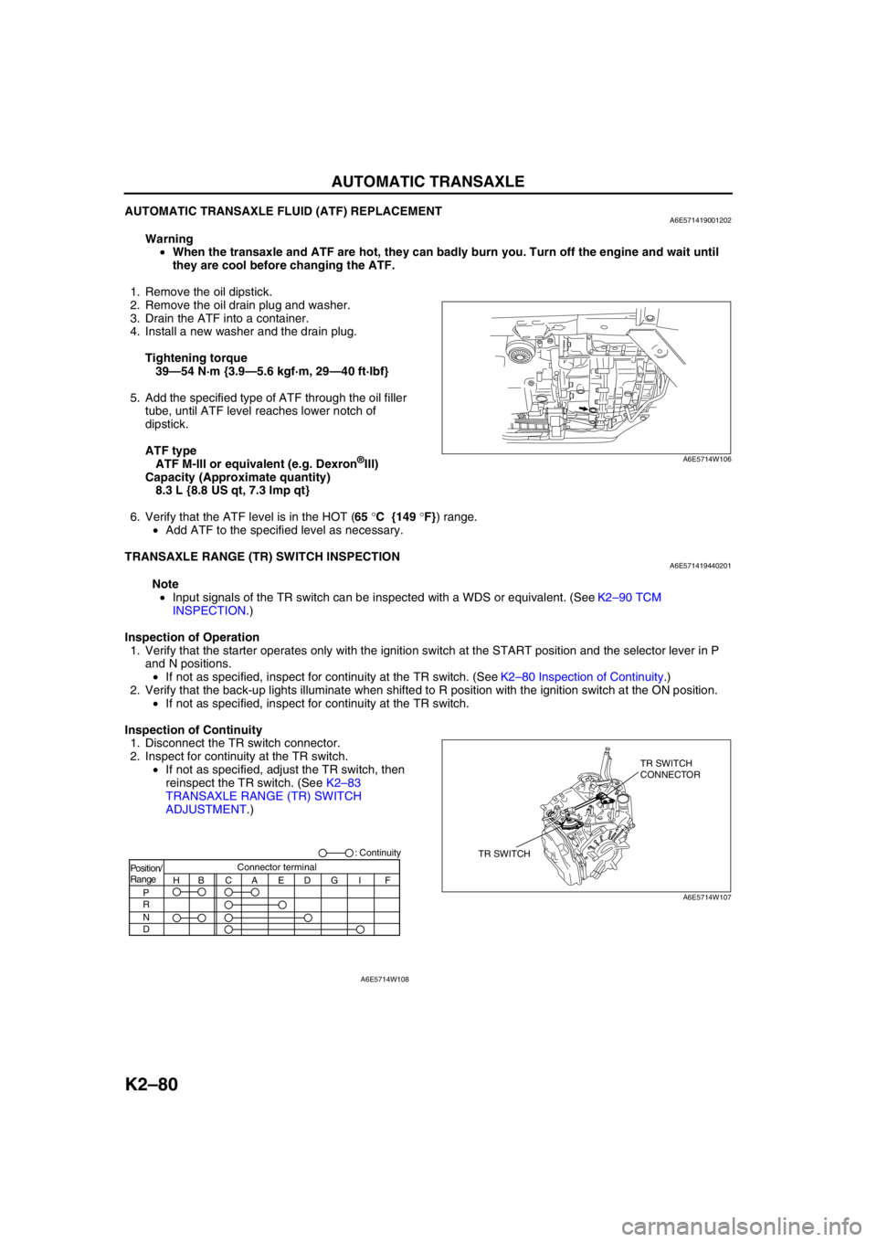
Inspection of Continuity
1. Disconnect the TR switch connector.
2. Inspect for continuity at the TR switch.
•If not as specified, adjust the TR switch, then
reinspect the TR switch. (See K2–83
TRANSAXLE RANGE (TR) SWITCH
ADJUSTMENT.)
A6E5714W106
TR SWITCHTR SWITCH
CONNECTOR
A6E5714W107
Position/
Range
H
P
R
N
DBCAEDGI FConnector terminal: Continuity
A6E5714W108
Page 514 of 909
AUTOMATIC TRANSAXLE
K2–99
K2
AUTOMATIC TRANSAXLE AND TRANSFER REMOVAL/INSTALLATIONA6E5714190902011. Disconnect the negative battery cable.
2. Remove the battery and battery tray.
3. Remove the aircleaner component. (See Sectin F.)
4. Remove the front tires and splash shield.
5. Remove the under cover.
6. Separate the steering shaft and steering hose. (See N–13 STEERING GEAR AND LINKAGE (4WD)
REMOVAL/INSTALLATION.)
7. Remove the front auto leveling sensor. (See Section T.)
8. Drain the ATF. (See K2–80 AUTOMATIC TRANSAXLE FLUID (ATF) REPLACEMENT.)
Warning
•Improperly jacking a transaxle is dangerous. It can slip off the jack and may cause serious injury.
Caution
•To prevent the torque converter and transaxle from separating, remove the transaxle without
tilting it toward the torque converter.
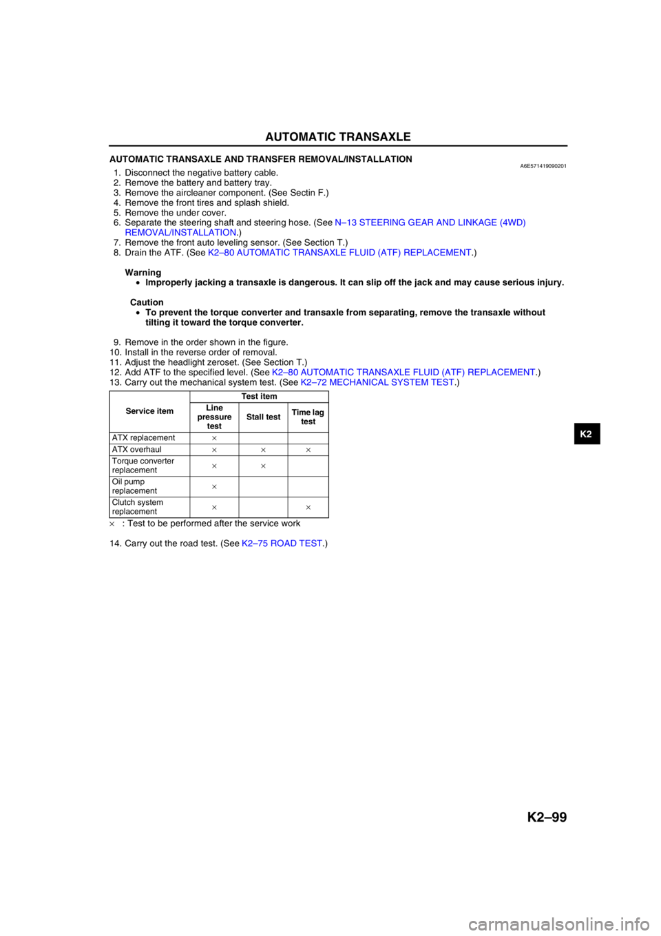
9. Remove in the order shown in the figure.
10. Install in the reverse order of removal.
11. Adjust the headlight zeroset. (See Section T.)
12. Add ATF to the specified level. (See K2–80 AUTOMATIC TRANSAXLE FLUID (ATF) REPLACEMENT.)
13. Carry out the mechanical system test. (See K2–72 MECHANICAL SYSTEM TEST.)
×: Test to be performed after the service work
14. Carry out the road test. (See K2–75 ROAD TEST.)
Service itemTest item
Line
pressure
testStall testTime lag
test
ATX replacement×
ATX overhaul×××
Torque converter
replacement××
Oil pump
replacement×
Clutch system
replacement××
Page 518 of 909
AUTOMATIC TRANSAXLE
K2–103
K2
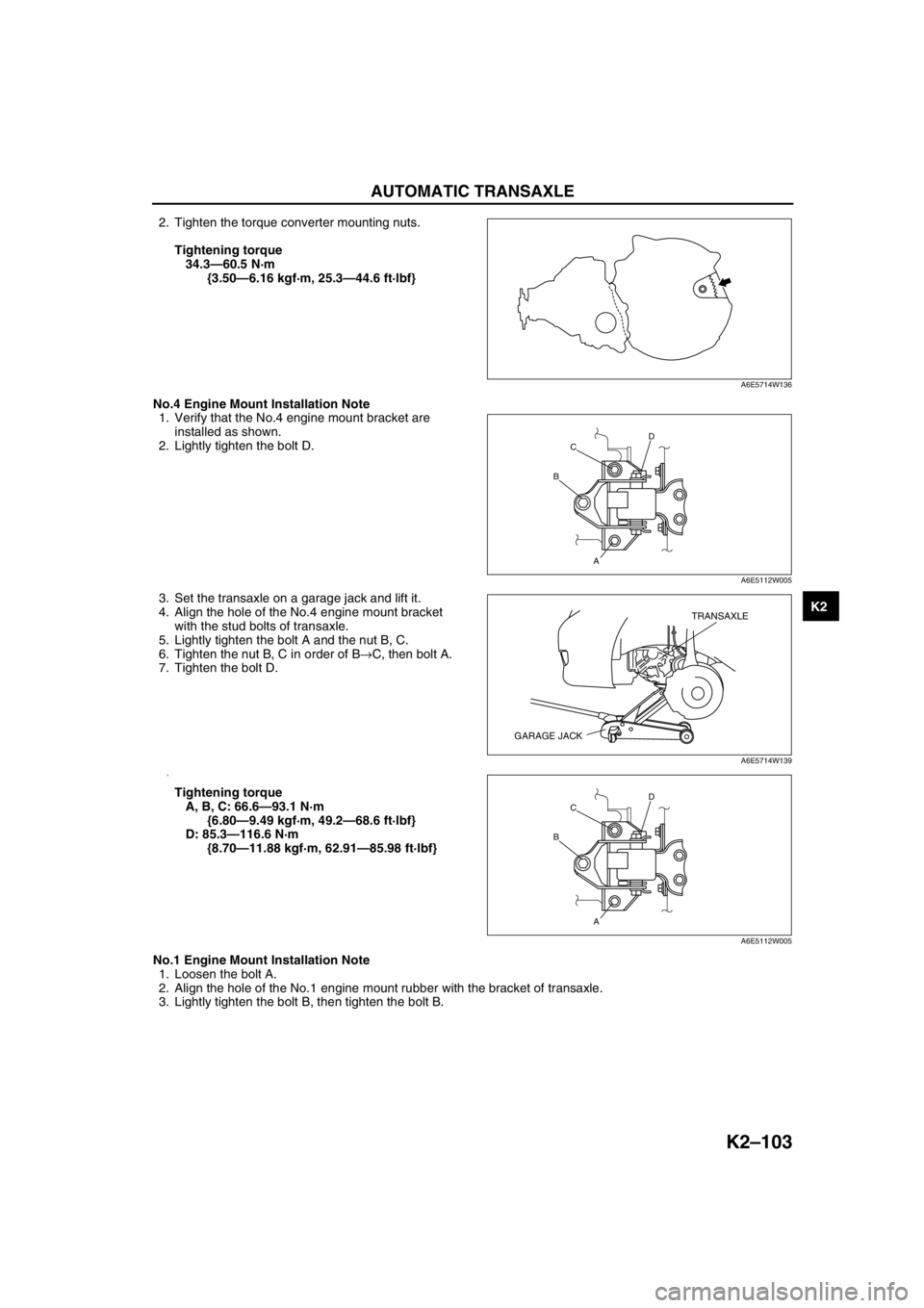
2. Tighten the torque converter mounting nuts.
Tightening torque
34.3—60.5 N·m
{3.50—6.16 kgf·m, 25.3—44.6 ft·lbf}
No.4 Engine Mount Installation Note
1. Verify that the No.4 engine mount bracket are
installed as shown.
2. Lightly tighten the bolt D.
3. Set the transaxle on a garage jack and lift it.
4. Align the hole of the No.4 engine mount bracket
with the stud bolts of transaxle.
5. Lightly tighten the bolt A and the nut B, C.
6. Tighten the nut B, C in order of B→C, then bolt A.
7. Tighten the bolt D.
8.
Tightening torque
A, B, C: 66.6—93.1 N·m
{6.80—9.49 kgf·m, 49.2—68.6 ft·lbf}
D: 85.3—116.6 N·m
{8.70—11.88 kgf·m, 62.91—85.98 ft·lbf}
No.1 Engine Mount Installation Note
1. Loosen the bolt A.
2. Align the hole of the No.1 engine mount rubber with the bracket of transaxle.
3. Lightly tighten the bolt B, then tighten the bolt B.
A6E5714W136
D
A BC
A6E5112W005
TRANSAXLE
GARAGE JACK
A6E5714W139
D
A BC
A6E5112W005