engine MAZDA 6 2002 Workshop Manual Suplement
[x] Cancel search | Manufacturer: MAZDA, Model Year: 2002, Model line: 6, Model: MAZDA 6 2002Pages: 909, PDF Size: 17.16 MB
Page 730 of 909

N–16
ENGINE SPEED SENSING POWER STEERING
POWER STEERING OIL PUMP (MZR-CD (RF TURBO)) REMOVAL/INSTALLATIONA6E6614326502011. Remove the air cleaner.
2. Remove the battery and battery tray.
3. Remove in the order indicated in the table.
4. Install in the reverse order of removal.
.
End Of Sie
OILOILR
R
R
4
3
1
229.4—44.1
{3.00—4.49, 21.7—32.5} 18.6—25.5
{1.90—2.60,
13.8—18.8}
N·m {kgf·m, ft·lbf}
A6E66142006
1 Pressure pipe
2 Return hose3 Power steering oil pump
4 O-ring
Page 731 of 909

ENGINE SPEED SENSING POWER STEERING
N–17
N
POWER STEERING OIL PUMP (MZR-CD (RF TURBO)) DISASSEMBLY/ASSEMBLYA6E661432650202
Note
•The following procedure is for replacement of the O-ring and oil seal only. Replace the pump component if
other repairs are necessary.
1. Disassemble in the order indicated in the table.
2. Assemble in the reverse order of disassembly.
.
9
8
7
5
4
3
10
6
1
2
15
16
14
13
11
12
SST
R
ATFTF
22—26
{2.3—2.6, 17—19}
N·m {kgf·m, ft·lbf}
R
ATFTF
R
R
ATFTF
ATFTF
ATFTF
R
31.1—47.0
{3.18—4.79, 23.0—34.6}
31.1—47.0
{3.18—4.79, 23.0—34.6}
A6E66142007
1 Power steering oil pump component
(See N–18 Power Steering Oil Pump Component
Disassembly Note)
2Clip
(See N–18 Clip Disassembly Note)
(See N–19 Clip Assembly Note)
3 Reservoir tank4 O-ring
5Joint
6 Connector
7 O-ring
8 Control valve
9Spring
Page 732 of 909

N–18
ENGINE SPEED SENSING POWER STEERING
Power Steering Oil Pump Component Disassembly Note
1. Secure the power pressure oil pump using the SST.
Caution
•Use the SST to prevent damage to the
pump when securing it in a vise.
Clip Disassembly Note
1. Lift up the clip tab using a flathead screwdriver.
2. Remove the clip by pushing it with a flathead
screwdriver and a hammer as shown in the figure.
Vane Assembly Note
1. Place the vanes in the rotor with the rounded
edges contacting the cam.
10 Rear pump body
(See N–19 Rear Pump Body Assembly Note)
11 Gasket
12 Cam ring
(See N–19 Cam Ring Assembly Note)13 Rotor
14 Vane
(See N–18 Vane Assembly Note)
15 Side plate
16 Power steering oil pump
49 F032 301
A6E66142010
CLIP
R
A6E66142008
A6E6316W013
Page 733 of 909

ENGINE SPEED SENSING POWER STEERING
N–19
N
Cam Ring Assembly Note
1. Install the cam ring in the front pump body with
the mark facing upward.
Rear Pump Body Assembly Note
1. After installing the rear body, manually turn the shaft to verify that it rotates smoothly.
Clip Assembly Note
1. Push the clip slowly in the direction shown in the
figure.
2. Confirm that the clip tab is securely fastened.
End Of Sie
A6E6316W014
CLIP
R
A6E66142009
Page 735 of 909

P–2
OUTLINE
OUTLINE OF CONSTRUCTIONA6E690201020201•The construction and operation of the braking system is the same as that of the current Mazda6 (GG) L8, LF,
L3 engine 2WD model, except for the following features. (See Mazda6 Training Manual 3359-1*-02C.)
End Of Sie
FEATURESA6E690201020202Modifications to match vehicle characteristics
•Due to the addition of the MZR-CD (RF Turbo) engine, the vacuum pump and vacuum switch have been
added.
•Due to the addition of the 4WD model, DSC HU/CM uses the forward-G signal from combine sensor to control
DSC.
End Of Sie
SPECIFICATIONSA6E690201020203
Bold frames: New specifications
End Of Sie
OUTLINE
ItemSpecification
New Mazda6 (GG, GW) Current Mazda6 (GG)
Brake pedalType Suspended
Pedal lever ratio 2.7
Max. stroke (mm {in}) 128.5 {5.06}
Master
cylinderType Tandem (with level sensor)
Cylinder diameter (mm {in}) 20.64 {0.813}
Front disc
brakeType Ventilated disc
Cylinder bore (mm {in}) 57.15 {2.250}
Pad dimensions (area × thickness) L8, LF (GCC specs.):
4,220 {6.75} × 10.0 {0.39}
LF (European (L.H.D. U.K.)
specs.), L3, MZR-CD (RF Turbo):
4,010 {6.42} × 12.0 {0.47}L8, LF (GCC specs.):
4,220 {6.75} × 10.0 {0.39}
LF (European (L.H.D. U.K.) specs.),
L3: 4,010 {6.42} × 12.0 {0.47} (mm
2 {in2} × mm {in})
Disc plate dimensions
(outer diameter × thickness)L8, LF (GCC specs.):
274 {10.8} × 24.0 {0.945}
LF (European (L.H.D. U.K.)
specs.), L3, MZR-CD (RF Turbo):
283 {11.1} × 25.0 {0.984}L8, LF (GCC specs.):
274 {10.8} × 24.0 {0.945}
LF (European (L.H.D. U.K.) specs.),
L3: 283 {11.1} × 25.0 {0.984} (mm {in} × mm {in})
Rear brake
(disc)Type Solid disc
Cylinder bore (mm {in}) 34.93 {1.375}
Pad dimensions (area × thickness)
2,810 {4.51} × 8.0 {0.31}
(mm
2 {in2} × mm {in})
Disc plate dimensions
(outer diameter × thickness)
280 {11.0} × 10.0 {0.39}
(mm {in})
Power brake
unitType Vacuum multiplier, single diaphragm
Diameter (mm {in}) 279 {10.9}
Braking force
control deviceTypeWith ABS: EBD (Electronic Brakeforce Distribution)
Without ABS: Dual proportioning valve
Parking brakeType Mechanical two-rear-wheel control
Operation system Center lever type
Brake fluid TypeEuropean (L.H.D. U.K.) specs.: SAE J1703, FMVSS116 DOT3 OR DOT4
GCC specs.: SAE J1703, FMVSS116 DOT3
Page 737 of 909

P–4
ABS/TCS
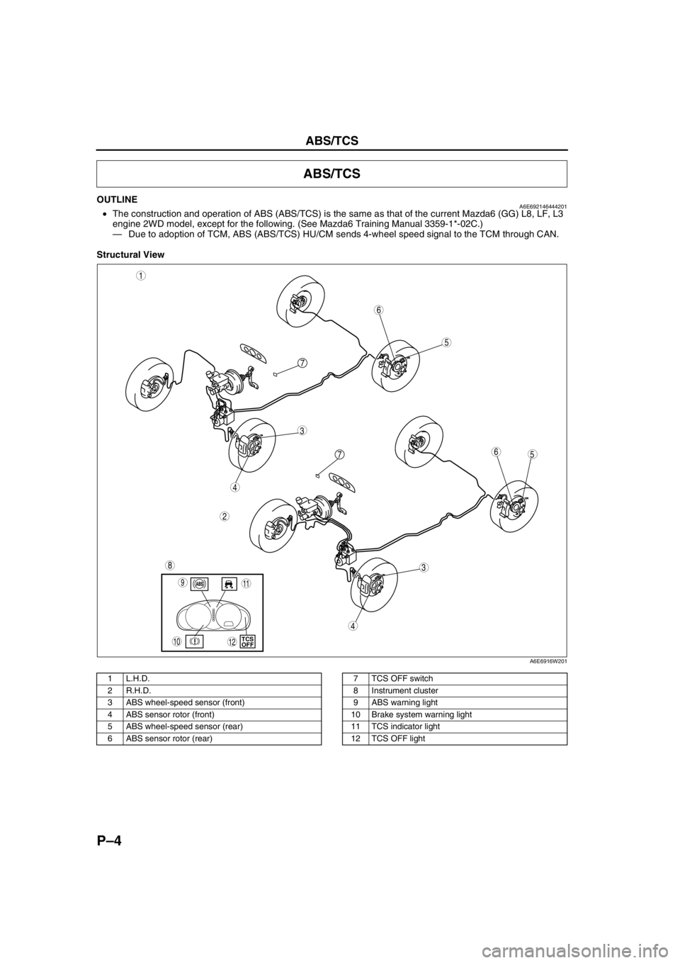
OUTLINEA6E692146444201•The construction and operation of ABS (ABS/TCS) is the same as that of the current Mazda6 (GG) L8, LF, L3
engine 2WD model, except for the following. (See Mazda6 Training Manual 3359-1*-02C.)
—Due to adoption of TCM, ABS (ABS/TCS) HU/CM sends 4-wheel speed signal to the TCM through CAN.
Structural View
.
ABS/TCS
5
3
1
2
6
7
5
3
6
8
4
4
7
9
10TCS
OFF
11
12
A6E6916W201
1 L.H.D.
2 R.H.D.
3 ABS wheel-speed sensor (front)
4 ABS sensor rotor (front)
5 ABS wheel-speed sensor (rear)
6 ABS sensor rotor (rear)7 TCS OFF switch
8 Instrument cluster
9 ABS warning light
10 Brake system warning light
11 TCS indicator light
12 TCS OFF light
Page 741 of 909

P–8
DYNAMIC STABILITY CONTROL
End Of SieCOMBINE SENSOR (FORWARD-G SENSOR)A6E692067650202Function
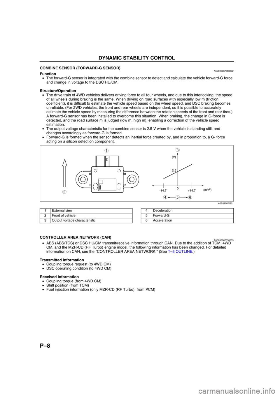
•The forward-G sensor is integrated with the combine sensor to detect and calculate the vehicle forward-G force
and change in voltage to the DSC HU/CM.
Structure/Operation
•The drive train of 4WD vehicles delivers driving force to all four wheels, and due to this interlocking, the speed
of all wheels during braking is the same. When driving on road surfaces with especially low m (friction
coefficient), it is difficult to estimate the vehicle speed based on the wheel speed, and DSC braking becomes
unreliable. (For 2WD vehicles, the front and rear wheels are independent, so it is possible to accurately
estimate the vehicle speed by measuring the difference between the rotation speeds of the front and rear tires.)
A forward-G sensor has been installed to overcome this situation. When braking, the change in G-force is
detected, and the road surface m is judged (low m, high m), enabling a correction of the vehicle speed
estimation.
•The output voltage characteristic for the combine sensor is 2.5 V when the vehicle is standing still, and
changes accordingly as forward-G is formed.
•Forward-G is formed when the sensor detects an inertial force created by, and in proportion to, a G- force
acting on a silicon detection component.
.
End Of Sie
CONTROLLER AREA NETWORK (CAN)A6E692067650203•ABS (ABS/TCS) or DSC HU/CM transmit/receive information through CAN. Due to the addition of TCM, 4WD
CM, and the MZR-CD (RF Turbo) engine model, the following information has been changed. For detailed
information on CAN, see the “CONTROLLER AREA NETWORK.” (See T–3 OUTLINE.)
Transmitted Information
•Coupling torque request (to 4WD CM)
•DSC operating condition (to 4WD CM)
Received Information
•Coupling torque (from 4WD CM)
•Shift position (from TCM)
•Fuel injection information (only MZR-CD (RF Turbo), from PCM)
End Of Sie
(V)
2.5
-14.70
+14.7(m/s
2)
45
3
6
2
1
A6E6920W201
1 External view
2 Front of vehicle
3 Output voltage characteristic4 Deceleration
5 Forward-G
6 Acceleration
Page 742 of 909

ON-BOARD DIAGNOSTIC
P–9
P
OUTLINEA6E697043000201•The operation of the on-board diagnostic system for ABS (ABS/TCS) or DSC is the same as that of the current
Mazda6 (GG) L8, LF, L3 engine 2WD model, except for the following. (See Mazda6 Training Manual
3359-1*-02C.)
— Due to the addition of the 4WD model, DTCs and PID data monitor has been added.
—Due to the addition of the MZR-CD (RF Turbo) engine model, the DTC C1119 fail-safe function and the
detection condition have been changed.
Fail-safe Function
Fail-safe function table
*1: When engine speed signal through CAN is out of specification, the light illuminates.*2: When engine speed signal through CAN is out of specification, the system is suspended.*3: When engine speed signal value through CAN is invalid, only brake TCS is available.*4: When fuel injection information through CAN is out of specification or invalid, only brake TCS is available.*5: When engine speed signal value through CAN is invalid, only brake DSC is available.*6: When the engine control system has a malfunction, only brake DSC is available.
PID/DATA Monitor Table
End Of Sie
ON-BOARD DIAGNOSTIC
Malfunc-
tion
locationDTC Fail-safe function
WDS
or
equiva-
lentWarning light illumination condition Control condition
ABS
warning
lightBRAKE
system
warning
light
(when
parking
brake is
released)DSC
(TCS)
OFF lightDSC
(TCS)
indicator
light ABS
controlEBD
controlTCS
controlDSC
controlBrake
assist
control
PCM and/
or engine
speed
signal lineC1119Not
Illuminated Not
Illuminated Not
Illuminated
*1Illuminated Available AvailableAvailable*2, *3, *4Available*2, *5, *6Available
Combine
sensor
(forward-
G) lineC1949
Illuminated Not
Illuminated Illuminated IlluminatedNot
availableAvailable—Not
availableNot
available
C1950
CAN line U2511Not
Illuminated Not
Illuminated Not
Illuminated Illuminated Available Available—Available Available
PID name input/output part Operation/unit
ACCLMTR Accelerometer ACCELERATION
Page 745 of 909

P–12
CONVENTIONAL BRAKE SYSTEM
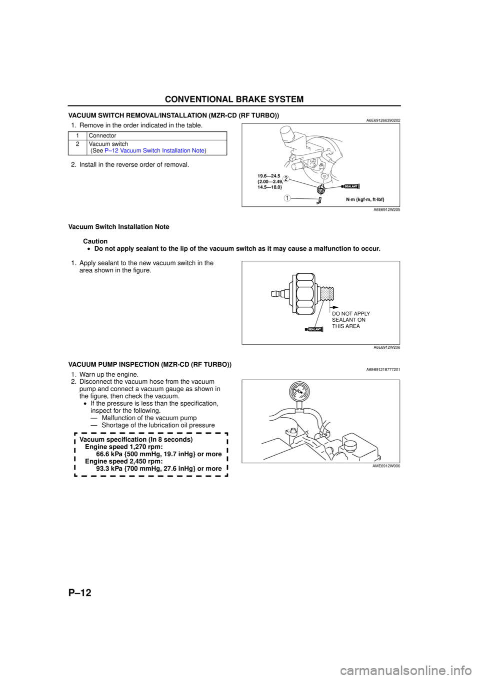
VACUUM SWITCH REMOVAL/INSTALLATION (MZR-CD (RF TURBO))A6E6912663902021. Remove in the order indicated in the table.
2. Install in the reverse order of removal.
Vacuum Switch Installation Note Caution• Do not apply sealant to the lip of the vacuum switch as it may cause a malfunction to occur.
1. Apply sealant to the new vacuum switch in the area shown in the figure.
End Of Sie
VACUUM PUMP INSPECTION (MZR-CD (RF TURBO))A6E6912187772011. Warn up the engine.
2. Disconnect the vacuum hose from the vacuum pump and connect a vacuum gauge as shown in
the figure, then check the vacuum.• If the pressure is less than the specification,
inspect for the following.
— Malfunction of the vacuum pump
— Shortage of the lubrication oil pressure
Vacuum specification (In 8 seconds) Engine speed 1,270 rpm: 66.6 kPa {500 mmHg, 19.7 inHg} or more
Engine speed 2,450 rpm: 93.3 kPa {700 mmHg, 27.6 inHg} or more
End Of Sie
1 Connector
2 Vacuum switch (See P –12 Vacu um S w itch Ins tal lat ion Note )
SEALANT
1
219.6—24.5
{2.00—2.49,
14.5—18.0}
N·m {kgf·m, ft·lbf}
A6E6912W205
SEALANT
DO NOT APPLY
SEALANT ON
THIS AREA
A6E6912W206
AME6912W006
Page 750 of 909

PARKING BRAKE SYSTEM, DYNAMIC STABILITY CONTROL
P–17
P
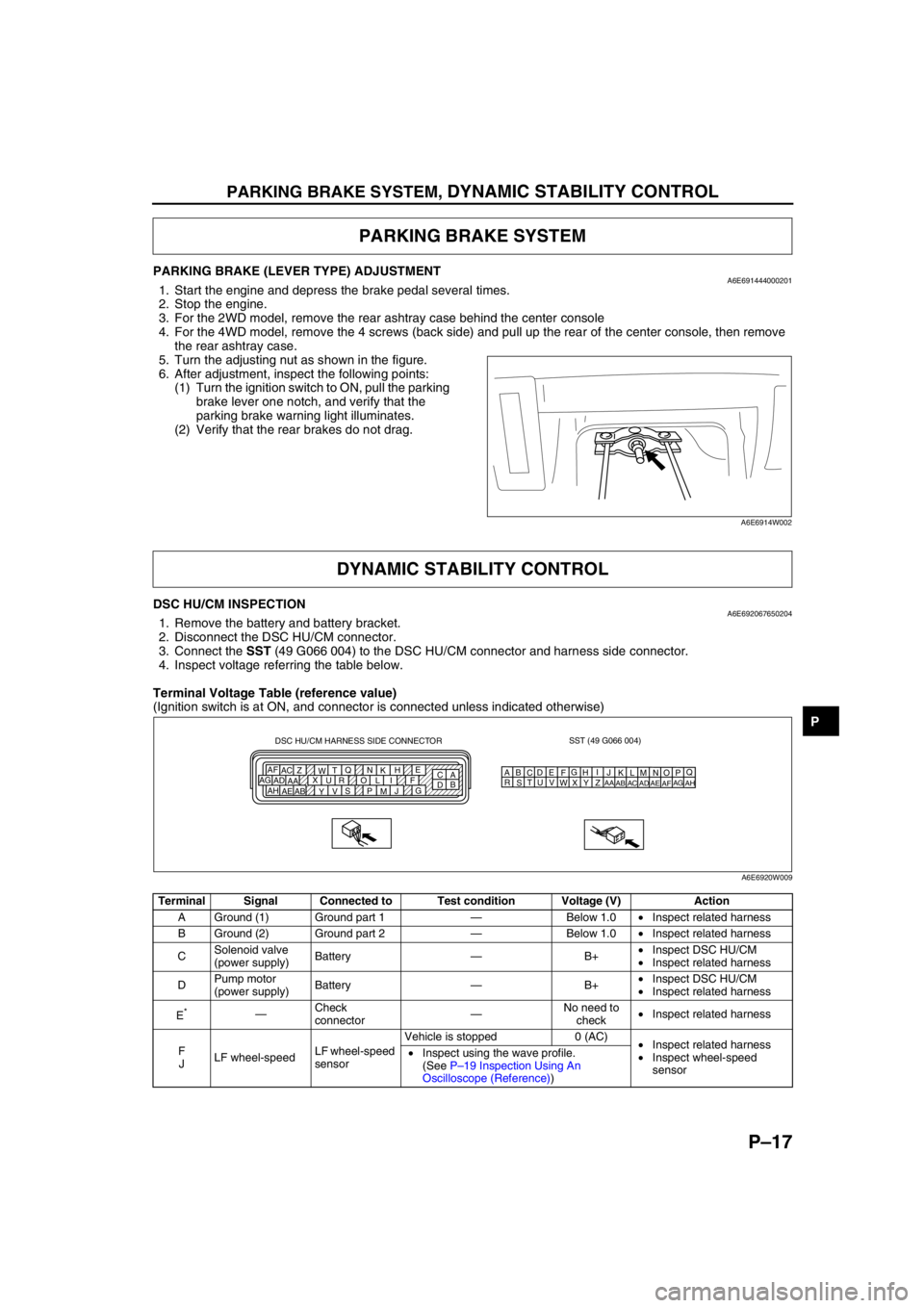
PARKING BRAKE (LEVER TYPE) ADJUSTMENTA6E6914440002011. Start the engine and depress the brake pedal several times.
2. Stop the engine.
3. For the 2WD model, remove the rear ashtray case behind the center console
4. For the 4WD model, remove the 4 screws (back side) and pull up the rear of the center console, then remove
the rear ashtray case.
5. Turn the adjusting nut as shown in the figure.
6. After adjustment, inspect the following points:
(1) Turn the ignition switch to ON, pull the parking
brake lever one notch, and verify that the
parking brake warning light illuminates.
(2) Verify that the rear brakes do not drag.
End Of Sie
DSC HU/CM INSPECTIONA6E6920676502041. Remove the battery and battery bracket.
2. Disconnect the DSC HU/CM connector.
3. Connect the SST (49 G066 004) to the DSC HU/CM connector and harness side connector.
4. Inspect voltage referring the table below.
Terminal Voltage Table (reference value)
(Ignition switch is at ON, and connector is connected unless indicated otherwise)
PARKING BRAKE SYSTEM
A6E6914W002
DYNAMIC STABILITY CONTROL
Terminal Signal Connected to Test condition Voltage (V) Action
A Ground (1) Ground part 1—Below 1.0•Inspect related harness
B Ground (2) Ground part 2—Below 1.0•Inspect related harness
CSolenoid valve
(power supply)Battery—B+•Inspect DSC HU/CM
•Inspect related harness
DPump motor
(power supply)Battery—B+•Inspect DSC HU/CM
•Inspect related harness
E
*—Check
connector—No need to
check•Inspect related harness
F
JLF wheel-speedLF wheel-speed
sensorVehicle is stopped 0 (AC)
•Inspect related harness
•Inspect wheel-speed
sensor •Inspect using the wave profile.
(See P–19 Inspection Using An
Oscilloscope (Reference))
SST (49 G066 004)
AQ
B
CDE
FG
HI
J DSC HU/CM HARNESS SIDE CONNECTOR
A
C E
H
K N Q
T
W Z AC AF
F I L O R U X
AA AD AG
G
J
M P S
V
Y AB AE AHB
DKN
T
WZ
AC
AFLO
RU
XAA
ADAGMP
SV
YAB
AEAH
A6E6920W009