engine MAZDA 6 2002 Workshop Manual Suplement
[x] Cancel search | Manufacturer: MAZDA, Model Year: 2002, Model line: 6, Model: MAZDA 6 2002Pages: 909, PDF Size: 17.16 MB
Page 682 of 909
M–52
REAR DIFFERENTIAL
Coupling Component and Rear Differential Component Removal/installation Note
Warning
•Make sure that the coupling component and rear differential component are securely supported
by the jack. If the coupling component and rear differential component fall, it could cause death,
serious injury, or vehicle damage.
1. Make sure that the coupling component and rear
differential component are securely supported by
the jack, and remove/install the component by
operating the jack gradually.
End Of Sie
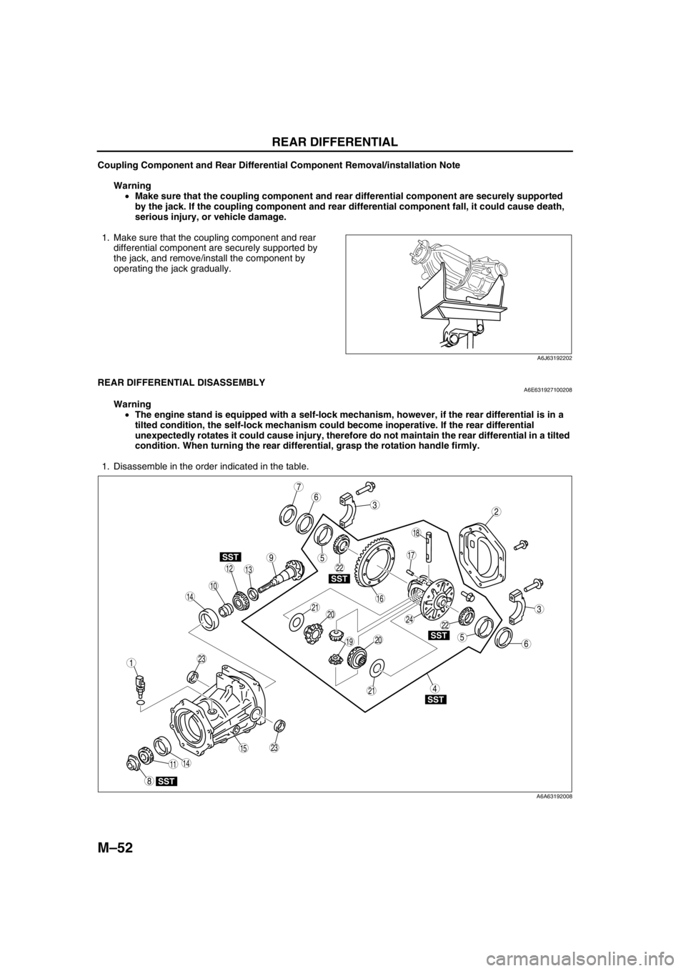
REAR DIFFERENTIAL DISASSEMBLYA6E631927100208
Warning
•The engine stand is equipped with a self-lock mechanism, however, if the rear differential is in a
tilted condition, the self-lock mechanism could become inoperative. If the rear differential
unexpectedly rotates it could cause injury, therefore do not maintain the rear differential in a tilted
condition. When turning the rear differential, grasp the rotation handle firmly.
1. Disassemble in the order indicated in the table.
.
A6J63192202
9
7
3
10
SST
SST
SST
SST
SST
6
18
14
14
1312
8
5
5
4
3
1
2
19
17
15
16
11
20
2024
23
23
21
21
22
22
6
A6A63192008
Page 683 of 909
REAR DIFFERENTIAL
M–53
M
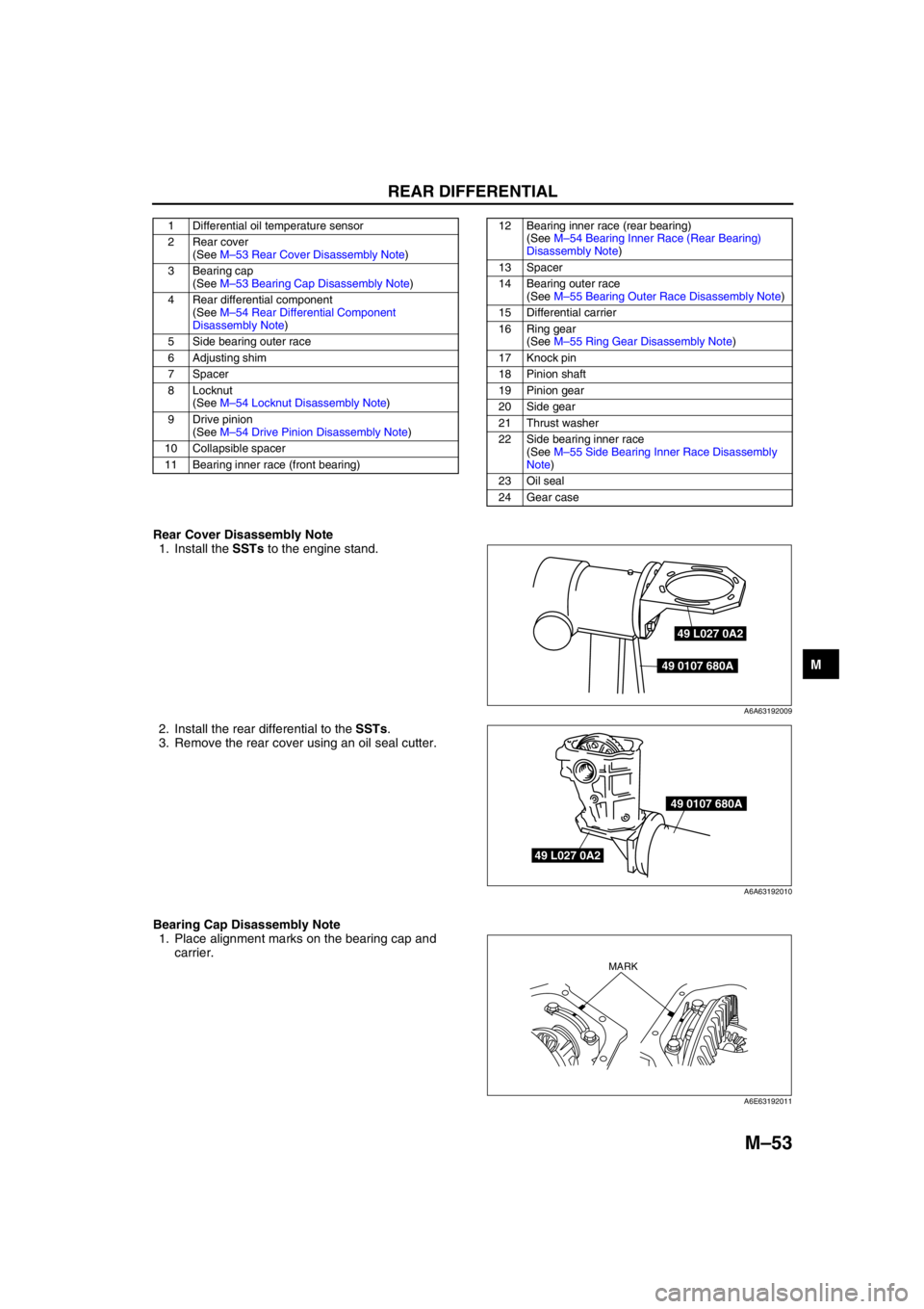
Rear Cover Disassembly Note
1. Install the SSTs to the engine stand.
2. Install the rear differential to the SSTs.
3. Remove the rear cover using an oil seal cutter.
Bearing Cap Disassembly Note
1. Place alignment marks on the bearing cap and
carrier.
1 Differential oil temperature sensor
2 Rear cover
(See M–53 Rear Cover Disassembly Note)
3 Bearing cap
(See M–53 Bearing Cap Disassembly Note)
4 Rear differential component
(See M–54 Rear Differential Component
Disassembly Note)
5 Side bearing outer race
6 Adjusting shim
7Spacer
8 Locknut
(See M–54 Locknut Disassembly Note)
9 Drive pinion
(See M–54 Drive Pinion Disassembly Note)
10 Collapsible spacer
11 Bearing inner race (front bearing)12 Bearing inner race (rear bearing)
(See M–54 Bearing Inner Race (Rear Bearing)
Disassembly Note)
13 Spacer
14 Bearing outer race
(See M–55 Bearing Outer Race Disassembly Note)
15 Differential carrier
16 Ring gear
(See M–55 Ring Gear Disassembly Note)
17 Knock pin
18 Pinion shaft
19 Pinion gear
20 Side gear
21 Thrust washer
22 Side bearing inner race
(See M–55 Side Bearing Inner Race Disassembly
Note)
23 Oil seal
24 Gear case
49 L027 0A2
49 0107 680A
A6A63192009
49 L027 0A2
49 0107 680A
A6A63192010
MARK
A6E63192011
Page 686 of 909
M–56
REAR DIFFERENTIAL
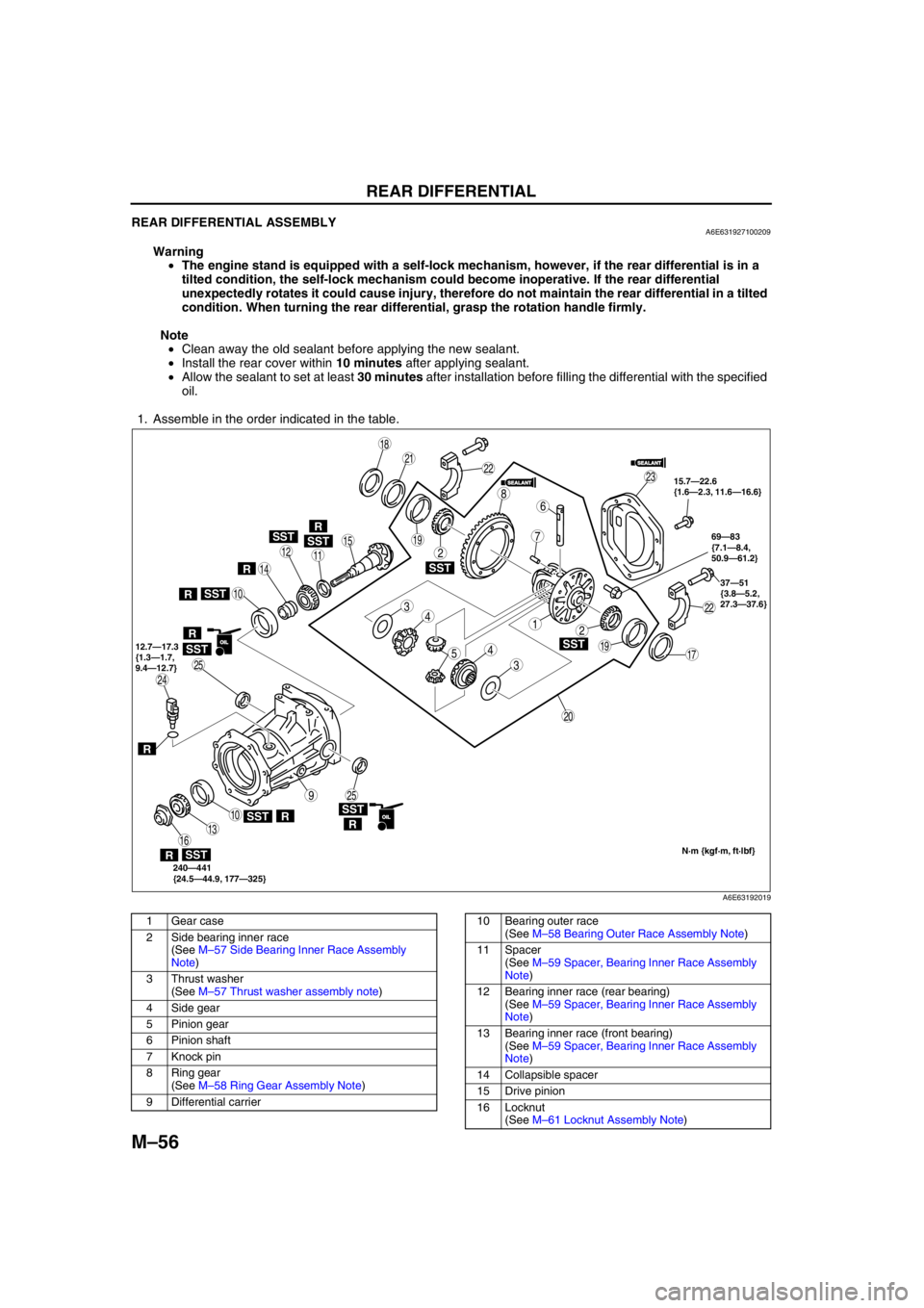
REAR DIFFERENTIAL ASSEMBLYA6E631927100209
Warning
•The engine stand is equipped with a self-lock mechanism, however, if the rear differential is in a
tilted condition, the self-lock mechanism could become inoperative. If the rear differential
unexpectedly rotates it could cause injury, therefore do not maintain the rear differential in a tilted
condition. When turning the rear differential, grasp the rotation handle firmly.
Note
•Clean away the old sealant before applying the new sealant.
•Install the rear cover within 10 minutes after applying sealant.
•Allow the sealant to set at least 30 minutes after installation before filling the differential with the specified
oil.
1. Assemble in the order indicated in the table.
.
SST
SST
SST
SSTSST
SST
SST
9
8
7
54
4
3
3
12
2
10
10
19
19
18
17
15
16
14
13
1112
20
25
25
24
23
21
22
22
R
SST
R
R
R
SSTR
RR
6
SEALANTSEALANT
SEALANTSEALANT
OILOIL
OILOIL
15.7—22.6
{1.6—2.3, 11.6—16.6}
37—51
{3.8—5.2,
27.3—37.6}
240—441
{24.5—44.9, 177—325} 12.7—17.3
{1.3—1.7,
9.4—12.7}69—83
{7.1—8.4,
50.9—61.2}
N·m {kgf·m, ft·lbf}
R
A6E63192019
1 Gear case
2 Side bearing inner race
(See M–57 Side Bearing Inner Race Assembly
Note)
3 Thrust washer
(See M–57 Thrust washer assembly note)
4 Side gear
5 Pinion gear
6Pinion shaft
7 Knock pin
8 Ring gear
(See M–58 Ring Gear Assembly Note)
9 Differential carrier10 Bearing outer race
(See M–58 Bearing Outer Race Assembly Note)
11 Spacer
(See M–59 Spacer, Bearing Inner Race Assembly
Note)
12 Bearing inner race (rear bearing)
(See M–59 Spacer, Bearing Inner Race Assembly
Note)
13 Bearing inner race (front bearing)
(See M–59 Spacer, Bearing Inner Race Assembly
Note)
14 Collapsible spacer
15 Drive pinion
16 Locknut
(See M–61 Locknut Assembly Note)
Page 699 of 909
ELECTRONIC 4WD CONTROL SYSTEM
M–69
M
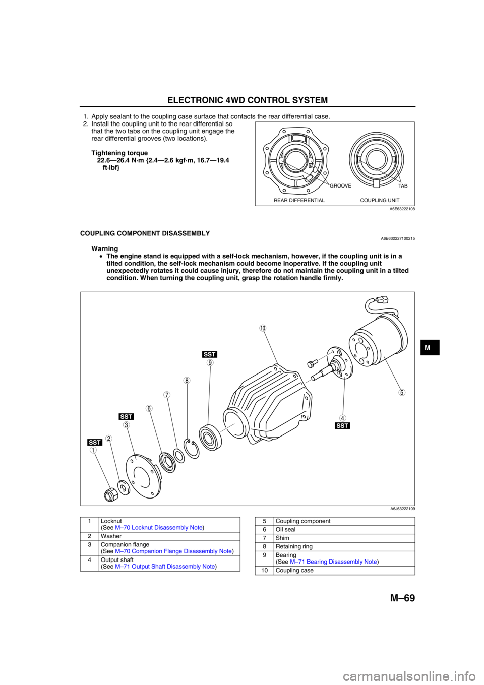
1. Apply sealant to the coupling case surface that contacts the rear differential case.
2. Install the coupling unit to the rear differential so
that the two tabs on the coupling unit engage the
rear differential grooves (two locations).
Tightening torque
22.6—26.4 N·m {2.4—2.6 kgf·m, 16.7—19.4
ft·lbf}
End Of Sie
COUPLING COMPONENT DISASSEMBLYA6E632227100215
Warning
•The engine stand is equipped with a self-lock mechanism, however, if the coupling unit is in a
tilted condition, the self-lock mechanism could become inoperative. If the coupling unit
unexpectedly rotates it could cause injury, therefore do not maintain the coupling unit in a tilted
condition. When turning the coupling unit, grasp the rotation handle firmly.
.
GROOVE
REAR DIFFERENTIAL COUPLING UNITTA B
A6E63222108
SST
SST
SST
SST
9
8
75
4
3
1
2
10
6
A6J63222109
1 Locknut
(See M–70 Locknut Disassembly Note)
2Washer
3 Companion flange
(See M–70 Companion Flange Disassembly Note)
4 Output shaft
(See M–71 Output Shaft Disassembly Note)5 Coupling component
6Oil seal
7Shim
8 Retaining ring
9 Bearing
(See M–71 Bearing Disassembly Note)
10 Coupling case
Page 700 of 909
M–70
ELECTRONIC 4WD CONTROL SYSTEM
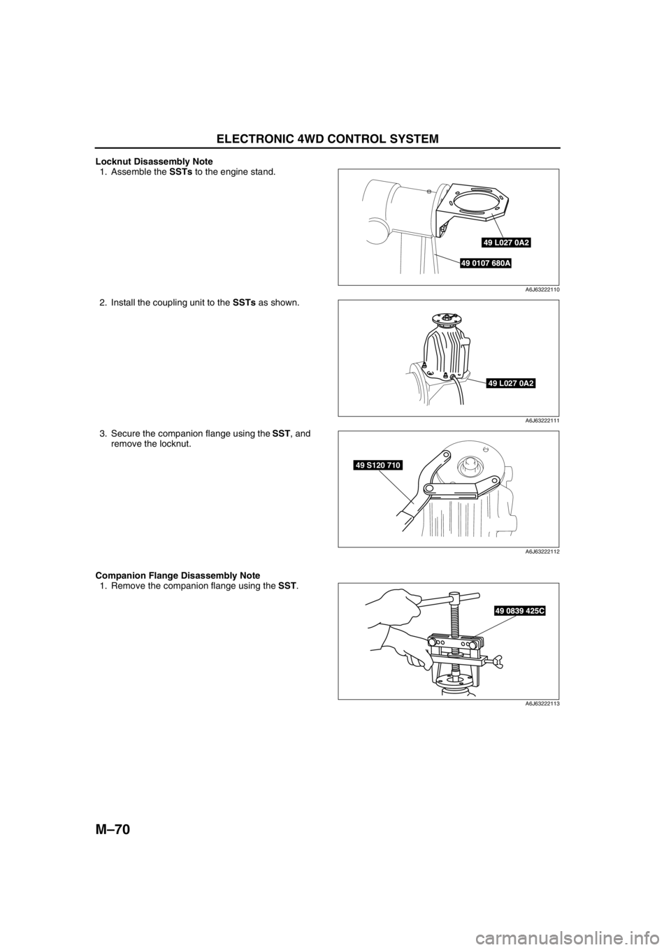
Locknut Disassembly Note
1. Assemble the SSTs to the engine stand.
2. Install the coupling unit to the SSTs as shown.
3. Secure the companion flange using the SST, and
remove the locknut.
Companion Flange Disassembly Note
1. Remove the companion flange using the SST.
49 L027 0A2
49 0107 680A
A6J63222110
49 L027 0A2
A6J63222111
49 S120 710
A6J63222112
49 0839 425C
A6J63222113
Page 702 of 909
M–72
ELECTRONIC 4WD CONTROL SYSTEM
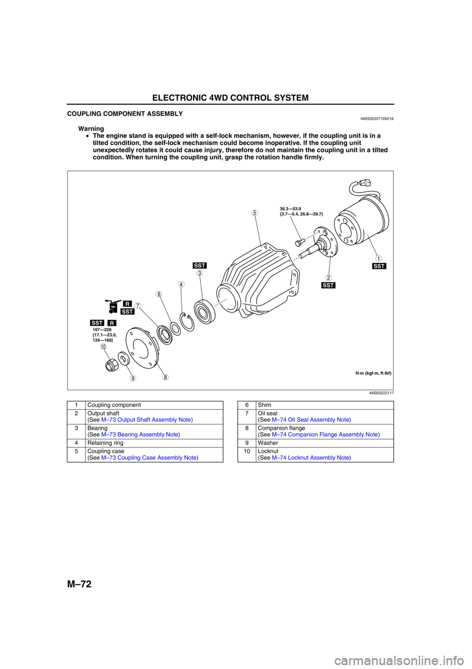
COUPLING COMPONENT ASSEMBLYA6E632227100216
Warning
•The engine stand is equipped with a self-lock mechanism, however, if the coupling unit is in a
tilted condition, the self-lock mechanism could become inoperative. If the coupling unit
unexpectedly rotates it could cause injury, therefore do not maintain the coupling unit in a tilted
condition. When turning the coupling unit, grasp the rotation handle firmly.
.
98
7
5
4
3
1
2
10
6
SST
SST
R
SST
SST
SST
R
OIL
36.3—53.9
{3.7—5.4, 26.8—39.7}
167—226
{17.1—23.0,
124—166}
N·m {kgf·m, ft·lbf}
A6E63222117
1 Coupling component
2 Output shaft
(See M–73 Output Shaft Assembly Note)
3 Bearing
(See M–73 Bearing Assembly Note)
4 Retaining ring
5 Coupling case
(See M–73 Coupling Case Assembly Note)6Shim
7 Oil seal
(See M–74 Oil Seal Assembly Note)
8 Companion flange
(See M–74 Companion Flange Assembly Note)
9Washer
10 Locknut
(See M–74 Locknut Assembly Note)
Page 710 of 909
M–80
ON-BOARD DIAGNOSTIC
End Of Sie
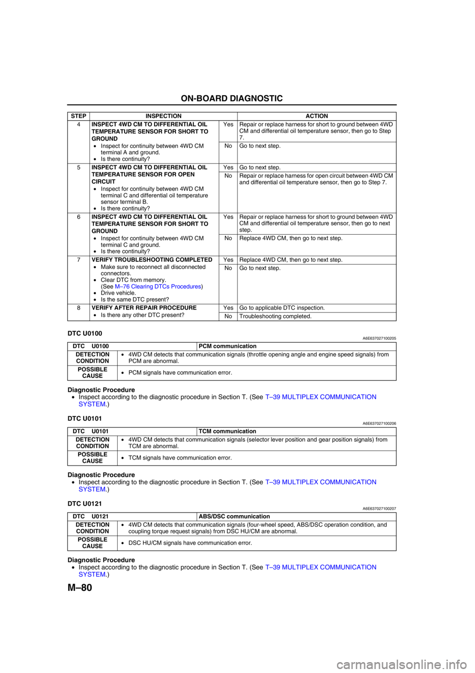
DTC U0100A6E637027100205
Diagnostic Procedure
•Inspect according to the diagnostic procedure in Section T. (See T–39 MULTIPLEX COMMUNICATION
SYSTEM.)
End Of Sie
DTC U0101A6E637027100206
Diagnostic Procedure
•Inspect according to the diagnostic procedure in Section T. (See T–39 MULTIPLEX COMMUNICATION
SYSTEM.)
End Of Sie
DTC U0121A6E637027100207
Diagnostic Procedure
•Inspect according to the diagnostic procedure in Section T. (See T–39 MULTIPLEX COMMUNICATION
SYSTEM.)
End Of Sie
4INSPECT 4WD CM TO DIFFERENTIAL OIL
TEMPERATURE SENSOR FOR SHORT TO
GROUND
•Inspect for continuity between 4WD CM
terminal A and ground.
•Is there continuity?Yes Repair or replace harness for short to ground between 4WD
CM and differential oil temperature sensor, then go to Step
7.
No Go to next step.
5INSPECT 4WD CM TO DIFFERENTIAL OIL
TEMPERATURE SENSOR FOR OPEN
CIRCUIT
•Inspect for continuity between 4WD CM
terminal C and differential oil temperature
sensor terminal B.
•Is there continuity?Yes Go to next step.
No Repair or replace harness for open circuit between 4WD CM
and differential oil temperature sensor, then go to Step 7.
6INSPECT 4WD CM TO DIFFERENTIAL OIL
TEMPERATURE SENSOR FOR SHORT TO
GROUND
•Inspect for continuity between 4WD CM
terminal C and ground.
•Is there continuity?Yes Repair or replace harness for short to ground between 4WD
CM and differential oil temperature sensor, then go to next
step.
No Replace 4WD CM, then go to next step.
7VERIFY TROUBLESHOOTING COMPLETED
•Make sure to reconnect all disconnected
connectors.
•Clear DTC from memory.
(See M–76 Clearing DTCs Procedures)
•Drive vehicle.
•Is the same DTC present?Yes Replace 4WD CM, then go to next step.
No Go to next step.
8VERIFY AFTER REPAIR PROCEDURE
•Is there any other DTC present?Yes Go to applicable DTC inspection.
No Troubleshooting completed. STEP INSPECTION ACTION
DTC U0100 PCM communication
DETECTION
CONDITION•4WD CM detects that communication signals (throttle opening angle and engine speed signals) from
PCM are abnormal.
POSSIBLE
CAUSE•PCM signals have communication error.
DTC U0101 TCM communication
DETECTION
CONDITION•4WD CM detects that communication signals (selector lever position and gear position signals) from
TCM are abnormal.
POSSIBLE
CAUSE•TCM signals have communication error.
DTC U0121 ABS/DSC communication
DETECTION
CONDITION•4WD CM detects that communication signals (four-wheel speed, ABS/DSC operation condition, and
coupling torque request signals) from DSC HU/CM are abnormal.
POSSIBLE
CAUSE•DSC HU/CM signals have communication error.
Page 714 of 909
M–84
TROUBLESHOOTING
End Of Sie
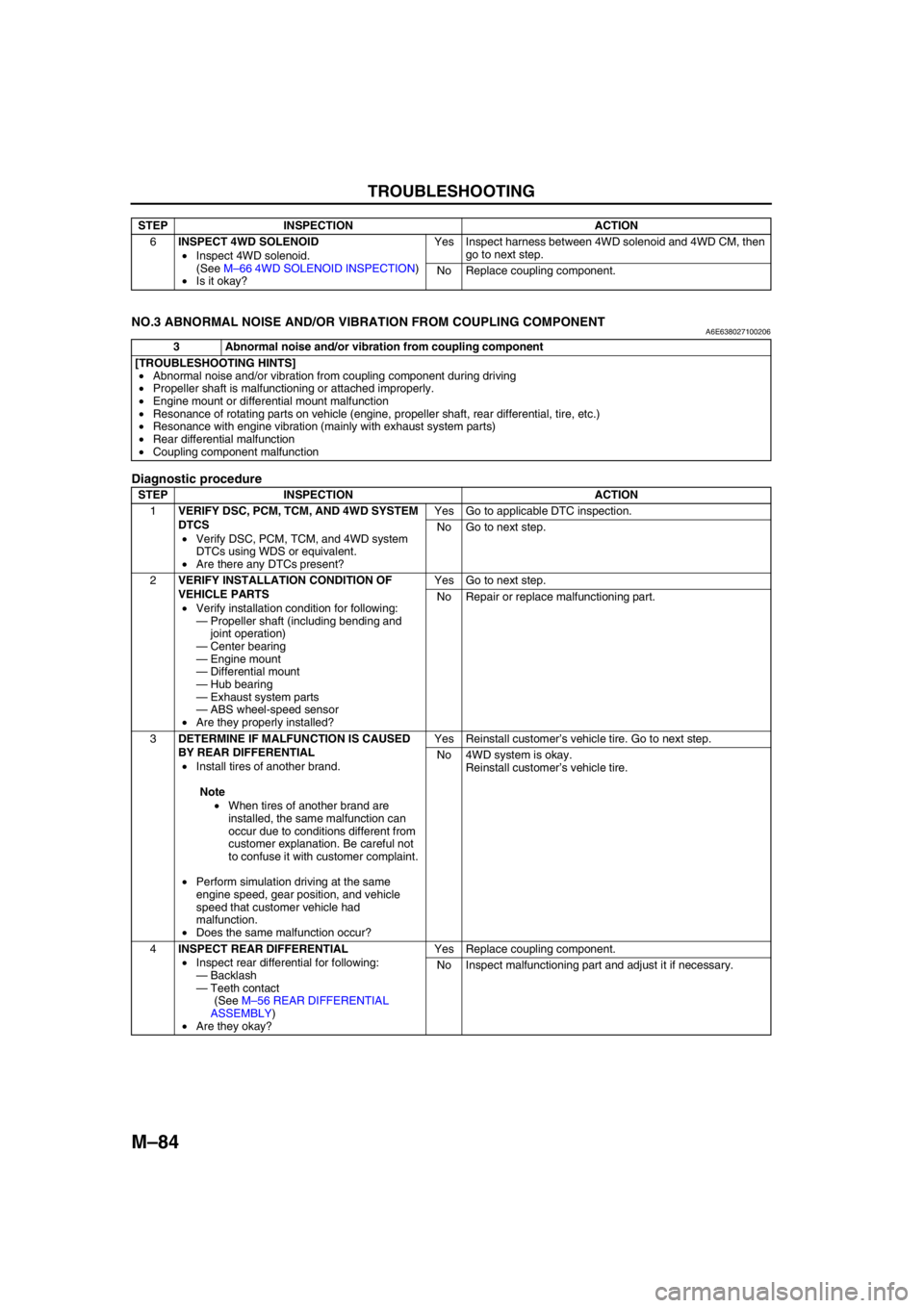
NO.3 ABNORMAL NOISE AND/OR VIBRATION FROM COUPLING COMPONENTA6E638027100206
Diagnostic procedure
End Of Sie
6INSPECT 4WD SOLENOID
•Inspect 4WD solenoid.
(See M–66 4WD SOLENOID INSPECTION)
•Is it okay?Yes Inspect harness between 4WD solenoid and 4WD CM, then
go to next step.
No Replace coupling component. STEP INSPECTION ACTION
3 Abnormal noise and/or vibration from coupling component
[TROUBLESHOOTING HINTS]
•Abnormal noise and/or vibration from coupling component during driving
•Propeller shaft is malfunctioning or attached improperly.
•Engine mount or differential mount malfunction
•Resonance of rotating parts on vehicle (engine, propeller shaft, rear differential, tire, etc.)
•Resonance with engine vibration (mainly with exhaust system parts)
•Rear differential malfunction
•Coupling component malfunction
STEP INSPECTION ACTION
1VERIFY DSC, PCM, TCM, AND 4WD SYSTEM
DTCS
•Verify DSC, PCM, TCM, and 4WD system
DTCs using WDS or equivalent.
•Are there any DTCs present?Yes Go to applicable DTC inspection.
No Go to next step.
2VERIFY INSTALLATION CONDITION OF
VEHICLE PARTS
•Verify installation condition for following:
—Propeller shaft (including bending and
joint operation)
—Center bearing
—Engine mount
—Differential mount
—Hub bearing
—Exhaust system parts
—ABS wheel-speed sensor
•Are they properly installed?Yes Go to next step.
No Repair or replace malfunctioning part.
3DETERMINE IF MALFUNCTION IS CAUSED
BY REAR DIFFERENTIAL
•Install tires of another brand.
Note
•When tires of another brand are
installed, the same malfunction can
occur due to conditions different from
customer explanation. Be careful not
to confuse it with customer complaint.
•Perform simulation driving at the same
engine speed, gear position, and vehicle
speed that customer vehicle had
malfunction.
•Does the same malfunction occur?Yes Reinstall customer’s vehicle tire. Go to next step.
No 4WD system is okay.
Reinstall customer’s vehicle tire.
4INSPECT REAR DIFFERENTIAL
•Inspect rear differential for following:
—Backlash
—Teeth contact
(See M–56 REAR DIFFERENTIAL
ASSEMBLY)
•Are they okay?Yes Replace coupling component.
No Inspect malfunctioning part and adjust it if necessary.
Page 715 of 909
N–1
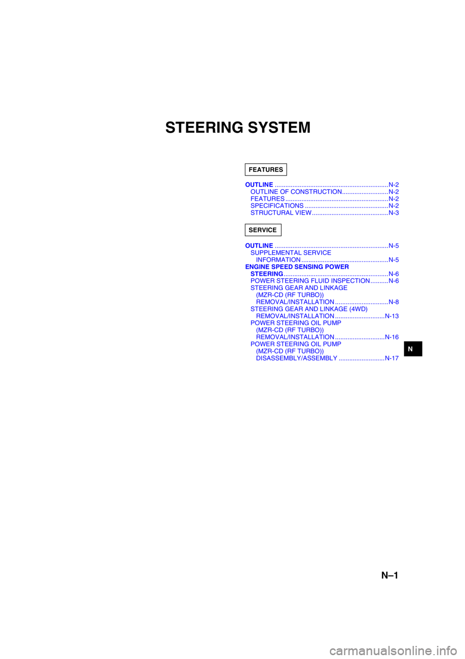
N
NSTEERING SYSTEM
OUTLINE................................................................ N-2
OUTLINE OF CONSTRUCTION.......................... N-2
FEATURES .......................................................... N-2
SPECIFICATIONS ............................................... N-2
STRUCTURAL VIEW ...........................................N-3
OUTLINE................................................................ N-5
SUPPLEMENTAL SERVICE
INFORMATION .................................................N-5
ENGINE SPEED SENSING POWER
STEERING........................................................... N-6
POWER STEERING FLUID INSPECTION ..........N-6
STEERING GEAR AND LINKAGE
(MZR-CD (RF TURBO))
REMOVAL/INSTALLATION ..............................N-8
STEERING GEAR AND LINKAGE (4WD)
REMOVAL/INSTALLATION ............................N-13
POWER STEERING OIL PUMP
(MZR-CD (RF TURBO))
REMOVAL/INSTALLATION ............................N-16
POWER STEERING OIL PUMP
(MZR-CD (RF TURBO))
DISASSEMBLY/ASSEMBLY .......................... N-17 FEATURES
SERVICE
Page 716 of 909
N–2
OUTLINE
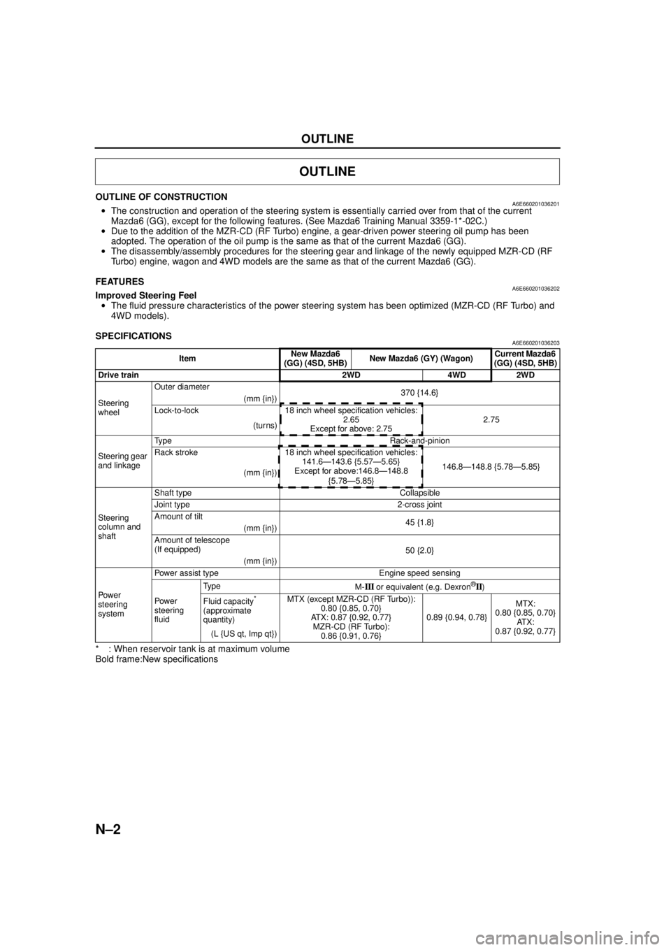
OUTLINE OF CONSTRUCTIONA6E660201036201•The construction and operation of the steering system is essentially carried over from that of the current
Mazda6 (GG), except for the following features. (See Mazda6 Training Manual 3359-1*-02C.)
• Due to the addition of the MZR-CD (RF Turbo) engine, a gear-driven power steering oil pump has been
adopted. The operation of the oil pump is the same as that of the current Mazda6 (GG).
• The disassembly/assembly procedures for the steering gear and linkage of the newly equipped MZR-CD (RF
Turbo) engine, wagon and 4WD models are the same as that of the current Mazda6 (GG).
End Of Sie
FEATURESA6E660201036202Improved Steering Feel
• The fluid pressure characteristics of the power steering system has been optimized (MZR-CD (RF Turbo) and
4WD models).
End Of Sie
SPECIFICATIONSA6E660201036203
* : When reservoir tank is at maximum volume
Bold frame:New specifications
End Of Sie
OUTLINE
Item New Mazda6
(GG) (4SD, 5HB) New Mazda6 (GY) (Wagon) Current Mazda6
(GG) (4SD, 5HB)
Drive train 2WD 4WD 2WD
Steering
wheel Outer diameter
370 {14.6}
(mm {in})
Lock-to-lock 18 inch wheel specification vehicles: 2.65
Except for above: 2.75 2.75
(turns)
Steering gear
and linkage Type Rack-and-pinion
Rack stroke 18 inch wheel specification vehicles:
141.6—143.6 {5.57—5.65}
Except for above:146.8—148.8
{5.78—5.85} 146.8—148.8 {5.78—5.85}
(mm {in})
Steering
column and
shaft Shaft type Collapsible
Joint type 2-cross joint
Amount of tilt
45 {1.8}
(mm {in})
Amount of telescope
(If equipped) 50 {2.0}
(mm {in})
Powe r
steering
system Power assist type Engine speed sensing
Pow er
steering
fluid
Ty p e
M-
III or equivalent (e.g. Dexron®II)
Fluid capacity
*
(approximate
quantity) MTX (except MZR-CD (RF Turbo)):
0.80 {0.85, 0.70}
ATX: 0.87 {0.92, 0.77} MZR-CD (RF Turbo):
0.86 {0.91, 0.76} 0.89 {0.94, 0.78}
MTX:
0.80 {0.85, 0.70}
AT X :
0.87 {0.92, 0.77}
(L {US qt, Imp qt})