PCM HARNESS SIDE CONNECTOR MAZDA 6 2002 Suplement Service Manual
[x] Cancel search | Manufacturer: MAZDA, Model Year: 2002, Model line: 6, Model: MAZDA 6 2002Pages: 909, PDF Size: 17.16 MB
Page 295 of 909

ON-BOARD DIAGNOSTIC
F2–143
F2
DTC P0380A6E407001082233
Diagnostic procedure
DTC P0380 Glow plug relay circuit malfunction
DETECTION
CONDITION•PCM monitors input voltage from glow plug relay while engine is running. PCM determines glow plug relay
circuit malfunction if input voltage from glow plug relay is as following:
—1.0 V or below when glow plug relay is on.
—4.0 V or above when glow plug relay is off.
POSSIBLE
CAUSE•Glow plug relay malfunction
•Connector or terminal malfunction
•Short to GND in wiring between glow plug relay terminal D and PCM terminal 68
•Short to GND in wiring between glow plug fuse and glow plug relay terminal A
•Short to GND in wiring between glow plug relay terminal C and PCM terminal 86
•Short to power circuit in wiring between glow plug relay terminal D and PCM terminal 68
•Short to power circuit in wiring between glow plug relay terminal C and PCM terminal 86
•Glow plug relay power and signal circuits short each other
•Open circuit in wiring between glow plug fuse and glow plug relay terminal A
•Open circuit in wiring between glow plug relay terminal B and GND
•Open circuit in wiring between glow plug relay terminal D and PCM terminal 68
•Open circuit in wiring between glow plug relay terminal C and PCM terminal 86
•PCM malfunction
STEP INSPECTION ACTION
1VERIFY RELATED REPAIR INFORMATION
AVAILABILITY
•Check for related Service Information
availability.
•Is any related repair information available?Yes Perform repair or diagnosis according to available Service
Information.
•If vehicle is not repaired, go to next step.
No Go to next step.
2INSPECT POOR CONNECTION OF GLOW
PLUG RELAY CONNECTOR
•Turn engine switch to OFF.
•Inspect for poor connection (damaged, pulled-
out terminals, corrosion, etc.).
•Is there any malfunction?Yes Repair or replace suspected terminal, go to Step 9.
No Go to next step.
A
B
C
D
GLOW FUSE
GLOW PLUG RELAY
AD
BC
6886
68 86PCM
54362
262
23598
4398
PCM
HARNESS SIDE CONNECTOR
7
GLOW PLUG RELAY
HARNESS SIDE CONNECTOR
Page 297 of 909

ON-BOARD DIAGNOSTIC
F2–145
F2
DTC P0504A6E407001082234
Diagnostic procedure
DTC P0504 Brake switch signal correlation malfunction
DETECTION
CONDITION•PCM monitors input signal from brake switch 1 and brake switch 2 while engine is running. PCM
determines brake switch signal correlation malfunction if input signal from brake switch 1 brake switch 2 is
as following:
—Brake switch 1 is ON and brake switch 2 is ON.
—Brake switch 1 is OFF and brake switch 2 is OFF.
POSSIBLE
CAUSE•Brake switch malfunction
•Connector or terminal malfunction
•Open circuit in wiring between main fuse and brake switch terminal B
•Open circuit in wiring between brake switch terminal D and PCM terminal 7
•Short to power circuit in wiring between brake switch terminal D and PCM terminal 7
•Open circuit in wiring between brake switch terminal C and GND
•Short to GND in wiring between brake switch terminal A and PCM terminal 34
•Open circuit in wiring between brake switch terminal A and PCM terminal 34
•PCM malfunction
STEP INSPECTION ACTION
1VERIFY RELATED REPAIR INFORMATION
AVAILABILITY
•Check for related Service Information
availability.
•Is any related repair information available?Yes Perform repair or diagnosis according to available Service
Information.
•If vehicle is not repaired, go to next step.
No Go to next step.
2CLASSIFY MALFUNCTION OF BRAKE SWITCH
1 OR BRAKE SWITCH 2
•Turn engine switch to ON (Engine OFF).
•Access BOO PID using WDS or equivalent.
•Verify that BOO PID is changed according to
brake pedal condition.
(See F2–65 PCM INSPECTION)
•Is BOO PID okay?Yes Go to Step 15.
No Go to next step.
3CLASSIFY HIGH INPUT OR LOW INPUT
•Turn engine switch to ON (Engine OFF).
•Access BOO PID using WDS or equivalent.
•Verify BOO PID during brake pedal operation.
•Is BOO PID always OFF?Yes Go to next step.
No Go to Step 10.
MAIN FUSE
BRAKE SWITCH
A B
CD
BRAKE SWITCHPCM
7
34
PCM
HARNESS SIDE CONNECTOR
HARNESS SIDE CONNECTOR
A
B C
D
7 34
4
6
7
8
910
4
10
12
1918
17
1516
1413
2015
Page 300 of 909

F2–148
ON-BOARD DIAGNOSTIC
DTC P0510A6E407001082235
Diagnostic procedure
DTC P0510 Idle switch circuit malfunction
DETECTION
CONDITION•PCM monitors input voltage from idle switch while engine is running. If input voltage from idle switch is B+
when accelerator position sensor No.1 voltage is below 0.7 V, PCM determines idle switch circuit
malfunction.
POSSIBLE
CAUSE•Idle switch malfunction
•Connector or terminal malfunction
•Open circuit in wiring between idle switch terminal B and GND
•Open circuit in wiring between idle switch terminal A and PCM terminal 31
•PCM malfunction
STEP INSPECTION ACTION
1VERIFY RELATED REPAIR INFORMATION
AVAILABILITY
•Check for related Service Information
availability.
•Is any related repair information available?Yes Perform repair or diagnosis according to available Service
Information.
•If vehicle is not repaired, go to next step.
No Go to next step.
BA IDLE SWITCH
A B
31 31PCM
4
2
23
65
IDLE SWITCH
HARNESS SIDE CONNECTORPCM
HARNESS SIDE CONNECTOR
Page 302 of 909

F2–150
ON-BOARD DIAGNOSTIC
DTC P0512A6E407001082236
DTC P0512 Engine switch circuit malfunction
DETECTION
CONDITION•PCM monitors input voltage from engine switch while engine is running. If input voltage from engine switch
is B+ when engine speed is 1,200 rpm or above, PCM determines engine switch circuit malfunction.
POSSIBLE
CAUSE•Engine switch malfunction
•Connector or terminal malfunction
•Short to power circuit in wiring between engine switch terminal A and PCM terminal 57
•PCM malfunction
ENGINE SWITCH
F
AMAIN FUSE
E
FC
DA
B
57 57PCM
4
2
235
ENGINE SWITCH
HARNESS SIDE CONNECTORPCM
HARNESS SIDE CONNECTOR
Page 304 of 909
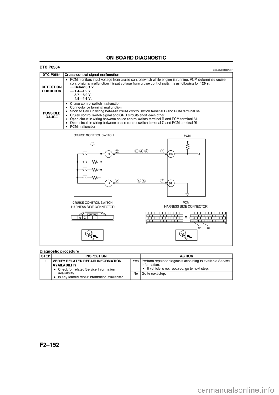
F2–152
ON-BOARD DIAGNOSTIC
DTC P0564A6E407001082237
Diagnostic procedure
DTC P0564 Cruise control signal malfunction
DETECTION
CONDITION•PCM monitors input voltage from cruise control switch while engine is running. PCM determines cruise
control signal malfunction if input voltage from cruise control switch is as following for 120 s:
—Below 0.1 V.
—1.4—1.9 V.
—3.7—3.9 V.
—4.5—4.6 V.
POSSIBLE
CAUSE•Cruise control switch malfunction
•Connector or terminal malfunction
•Short to GND in wiring between cruise control switch terminal B and PCM terminal 64
•Cruise control switch signal and GND circuits short each other
•Open circuit in wiring between cruise control switch terminal B and PCM terminal 64
•Open circuit in wiring between cruise control switch terminal C and PCM terminal 91
•PCM malfunction
STEP INSPECTION ACTION
1VERIFY RELATED REPAIR INFORMATION
AVAILABILITY
•Check for related Service Information
availability.
•Is any related repair information available?Yes Perform repair or diagnosis according to available Service
Information.
•If vehicle is not repaired, go to next step.
No Go to next step.
CRUISE CONTROL SWITCH
PCM
B
C64
91
CRUISE CONTROL SWITCH
HARNESS SIDE CONNECTORPCM
HARNESS SIDE CONNECTOR
BC
64 91
2
2
543
4
7
6
78
Page 305 of 909

ON-BOARD DIAGNOSTIC
F2–153
F2
End Of Sie
2INSPECT POOR CONNECTION OF CRUISE
CONTROL SWITCH CONNECTOR
•Turn engine switch to OFF.
•Inspect for poor connection (damaged, pulled-
out terminals, corrosion, etc.).
•Is there any malfunction?Yes Repair or replace suspected terminal, go to Step 9.
No Go to next step.
3INSPECT CRUISE CONTROL SWITCH SIGNAL
CIRCUIT FOR SHORT TO GND
•Turn engine switch to OFF.
•Inspect continuity between cruise control
switch terminal B and body GND.
•Is there continuity?Yes Repair or replace harness for short to GND, go to Step 9.
No Go to next step.
4INSPECT CRUISE CONTROL SWITCH CIRCUIT
FOR SHORT WITH EACH OTHER
•Turn engine switch to OFF.
•Inspect continuity between cruise control
switch terminals B and C.
•Is there continuity?Yes Repair or replace harness for short with each other, go to
Step 9.
No Go to next step.
5INSPECT CRUISE CONTROL SWITCH SIGNAL
CIRCUIT FOR OPEN
•Turn engine switch to ON. (Engine OFF)
•Inspect voltage at cruise control switch terminal
B (harness side).
•Is voltage below 1.0 V?Yes Repair or replace harness for open, go to Step 9.
No Go to next step.
6INSPECT CRUISE CONTROL SWITCH
•Inspect cruise control switch.
•Is there any malfunction?Yes Replace cruise control switch, go to Step 9.
No Go to next step.
7INSPECT POOR CONNECTION OF PCM
CONNECTOR
•Turn engine switch to OFF.
•Inspect for poor connection (damaged, pulled-
out terminals, corrosion, etc.).
•Is there any malfunction?Yes Repair or replace suspected terminal, go to Step 9.
No Go to next step.
8INSPECT CRUISE CONTROL SWITCH GND
CIRCUIT FOR OPEN
•Turn engine switch to OFF.
•Inspect continuity between cruise control
switch terminal C and PCM terminal 91.
•Is there continuity?Yes Go to next step.
No Repair or replace harness for open, go to next step.
9VERIFY TROUBLESHOOTING OF DTC P0564
COMPLETED
•Make sure to reconnect all disconnected
connectors.
•Clear DTC from PCM memory using WDS or
equivalent.
•Start engine.
•Is same DTC present?Yes Replace PCM, go to next step.
(See F2–64 PCM REMOVAL/INSTALLATION)
No Go to next step.
10VERIFY AFTER REPAIR PROCEDURE
•Perform “After Repair Procedure”.
(See F2–86 AFTER REPAIR PROCEDURE)
•Is there any DTC present?Yes Go to applicable DTC inspection.
(See F2–87 DTC TABLE)
No Troubleshooting completed. STEP INSPECTION ACTION
Page 308 of 909

F2–156
ON-BOARD DIAGNOSTIC
DTC P0661A6E407001082241
Diagnostic procedure
DTC P0661 VSC solenoid valve circuit low input
DETECTION
CONDITION•PCM monitors input voltage from VSC solenoid valve while engine is running. If input voltage from VSC
solenoid valve is below 0.1 V, PCM determines suction control valve circuit low input.
POSSIBLE
CAUSE•VSC solenoid valve malfunction
•Connector or terminal malfunction
•Short to GND in wiring between VSC solenoid valve terminal A and PCM control relay terminal C
•Short to GND in wiring between VSC solenoid valve terminal B and PCM terminal 101
•Open circuit in wiring between VSC solenoid valve terminal PCM control relay terminal C
•Open circuit in wiring between VSC solenoid valve terminal B and PCM terminal 101
•PCM malfunction
STEP INSPECTION ACTION
1PERFORM DTC CONFIRMATION PROCEDURE
•Perform “DTC Confirmation Procedure”.
(See F2–85 DTC CONFIRMATION
PROCEDURE)
•Is same DTC present during KOEO or KOER
self-test?Yes Go to next step.
No Intermittent concern exists. Go to “Intermittent Concern
Troubleshooting”.
(See F2–227 INTERMITTENT CONCERN
TROUBLESHOOTING)
A
B VSC SOLENOID VALVEPCM
101 A B3
632
6
5101
4
2
PCM CONTROL RELAY
TERMINAL C
VSC SOLENOID VALVE
HARNESS SIDE CONNECTORPCM
HARNESS SIDE CONNECTOR
Page 310 of 909

F2–158
ON-BOARD DIAGNOSTIC
DTC P0662A6E407001082242
DTC P0662 VSC solenoid valve circuit high input
DETECTION
CONDITION•PCM monitors input voltage from VSC solenoid valve while engine is running. If input voltage from VSC
solenoid valve is above B+, PCM determines suction control valve circuit high input.
POSSIBLE
CAUSE•VSC solenoid valve malfunction
•Connector or terminal malfunction
•Short to power circuit in wiring between VSC solenoid valve terminal B and PCM terminal 101
•PCM malfunction
A
B VSC SOLENOID VALVE
A
B
101101PCM
4
2
235
VSC SOLENOID VALVE
HARNESS SIDE CONNECTORPCM CONTROL RELAY
TERMINAL C
PCM
HARNESS SIDE CONNECTOR
Page 312 of 909
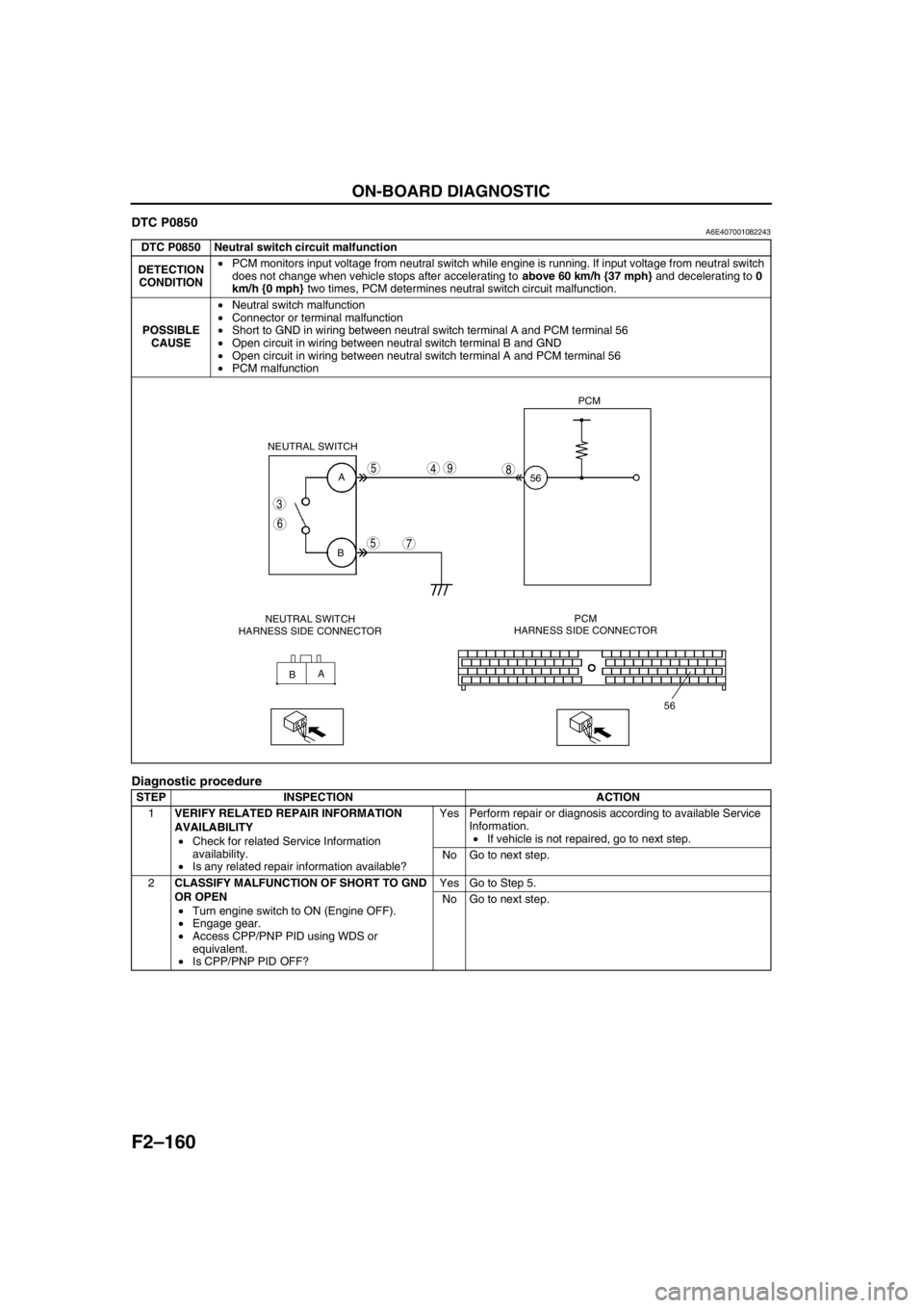
F2–160
ON-BOARD DIAGNOSTIC
DTC P0850A6E407001082243
Diagnostic procedure
DTC P0850 Neutral switch circuit malfunction
DETECTION
CONDITION•PCM monitors input voltage from neutral switch while engine is running. If input voltage from neutral switch
does not change when vehicle stops after accelerating to above 60 km/h {37 mph} and decelerating to 0
km/h {0 mph} two times, PCM determines neutral switch circuit malfunction.
POSSIBLE
CAUSE•Neutral switch malfunction
•Connector or terminal malfunction
•Short to GND in wiring between neutral switch terminal A and PCM terminal 56
•Open circuit in wiring between neutral switch terminal B and GND
•Open circuit in wiring between neutral switch terminal A and PCM terminal 56
•PCM malfunction
STEP INSPECTION ACTION
1VERIFY RELATED REPAIR INFORMATION
AVAILABILITY
•Check for related Service Information
availability.
•Is any related repair information available?Yes Perform repair or diagnosis according to available Service
Information.
•If vehicle is not repaired, go to next step.
No Go to next step.
2CLASSIFY MALFUNCTION OF SHORT TO GND
OR OPEN
•Turn engine switch to ON (Engine OFF).
•Engage gear.
•Access CPP/PNP PID using WDS or
equivalent.
•Is CPP/PNP PID OFF?Yes Go to Step 5.
No Go to next step.
A
B
A
B NEUTRAL SWITCH
56PCM
56
3
6
5
5
7
498
NEUTRAL SWITCH
HARNESS SIDE CONNECTORPCM
HARNESS SIDE CONNECTOR
Page 314 of 909
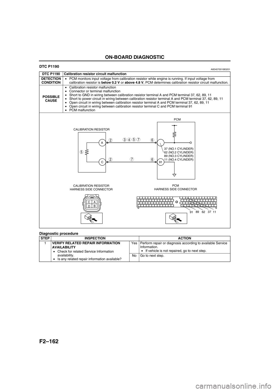
F2–162
ON-BOARD DIAGNOSTIC
DTC P1190A6E407001083201
Diagnostic procedure
DTC P1190 Calibration resistor circuit malfunction
DETECTION
CONDITION•PCM monitors input voltage from calibration resistor while engine is running. If input voltage from
calibration resistor is below 0.2 V or above 4.8 V, PCM determines calibration resistor circuit malfunction.
POSSIBLE
CAUSE•Calibration resistor malfunction
•Connector or terminal malfunction
•Short to GND in wiring between calibration resistor terminal A and PCM terminal 37, 62, 89, 11
•Short to power circuit in wiring between calibration resistor terminal A and PCM terminal 37, 62, 89, 11
•Open circuit in wiring between calibration resistor terminal A and PCM terminal 37, 62, 89, 11
•Open circuit in wiring between calibration resistor terminal C and PCM terminal 91
•PCM malfunction
STEP INSPECTION ACTION
1VERIFY RELATED REPAIR INFORMATION
AVAILABILITY
•Check for related Service Information
availability.
•Is any related repair information available?Yes Perform repair or diagnosis according to available Service
Information.
•If vehicle is not repaired, go to next step.
No Go to next step.
A
C
C
A
DBPCM
HARNESS SIDE CONNECTOR91PCM
CALIBRATION RESISTOR
5
2
2
5437
7
6
6
11 37
62 89
91
37 (NO.1 CYLINDER)
62 (NO.2 CYLINDER)
89 (NO.3 CYLINDER)
11 (NO.4 CYLINDER)
CALIBRATION RESISTOR
HARNESS SIDE CONNECTOR