brake sensor MAZDA 6 2002 Suplement Owner's Manual
[x] Cancel search | Manufacturer: MAZDA, Model Year: 2002, Model line: 6, Model: MAZDA 6 2002Pages: 909, PDF Size: 17.16 MB
Page 217 of 909
CONTROL SYSTEM
F2–65
F2
End Of SiePCM INSPECTIONA6E404018881208Using WDS or Equivalent
Caution
•The PCM terminal voltage vary with change in measuring conditions and vehicle conditions.
Always carry out a total inspection of the input systems, output systems, and PCM to determine
the cause of trouble. Otherwise, diagnosis will be incorrect.
Note
•For replace the PCM, setup the WDS and perform the following.
—“PCM configuration” (See F2–68 PCM CONFIGURATION.)
—“Correction after Parts Installation” (See F2–34 Correction after Parts Installation.)
1. Connect the WDS or equivalent to the DLC-2. (See F2–85 ON-BOARD DIAGNOSTIC TEST.)
2. Turn the engine switch to ON.
3. Measure the PID value.
•If PID value is not within the specification, follow the instructions in ACTION column.
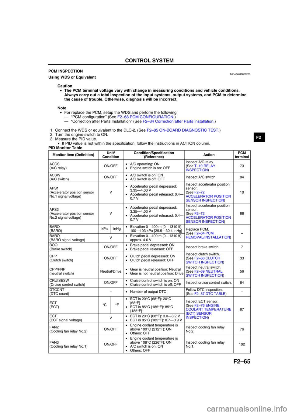
PID Monitor Table
Monitor item (Definition)Unit/
ConditionCondition/Specification
(Reference)ActionPCM
terminal
ACCS
(A/C relay)ON/OFF•A/C operating: ON
•Engine switch is on: OFFInspect A/C relay.
(See T–19 RELAY
INSPECTION)73
ACSW
(A/C switch)ON/OFF•A/C switch is on: ON
•A/C switch is off: OFFInspect A/C switch. 84
APS1
(Accelerator position sensor
No.1 signal voltage)V•Accelerator pedal depressed:
3.35—4.03 V
•Accelerator pedal released: 0.4—
0.7 VInspect accelerator position
sensor.
(See F2–72
ACCELERATOR POSITION
SENSOR INSPECTION)10
APS2
(Accelerator position sensor
No.2 signal voltage)V•Accelerator pedal depressed:
3.35—4.03 V
•Accelerator pedal released: 0.4—
0.7 VInspect accelerator position
sensor.
(See F2–72
ACCELERATOR POSITION
SENSOR INSPECTION)88
BARO
(BARO)kPa inHg•Elevation 0—400 m {0—1310 ft}:
100—103 kPa {29.5—30.4 inHg}Replace PCM.
(See F2–64 PCM
REMOVAL/INSTALLATION)–
BARO
(BARO signal voltage)V•Elevation 0—400 m {0—1310 ft}:
approx. 4.0 V
BOO
(Brake switch)ON/OFF•Brake pedal depressed: ON
•Brake pedal released: OFFInspect brake switch. 7
CPP
(Clutch switch)ON/OFF•Clutch pedal depressed: ON
•Clutch pedal released: OFFInspect clutch switch.
(See F2–68 CLUTCH
SWITCH INSPECTION)33
CPP/PNP
(neutral switch)Neutral/Drive•Gear is neutral position: Neutral
•Gear is not neutral position: DriveInspect neutral switch.
(See F2–69 NEUTRAL
SWITCH INSPECTION)56
CRUISESW
(Cruise control switch)ON/OFF•Cruise control switch is on: ON
•Cruise control switch is off: OFFInspect cruise control switch. 64
DTCCNT
(DTC count)–•Number of output DTCFollow DTC inspection.
(See F2–87 DTC TABLE)–
ECT
(ECT)°C°F•ECT is 20°C {68°F}: 20°C
{68°F}
•ECT is 85°C {185°F}: 85°C
{185°F}Inspect ECT sensor.
(See F2–76 ENGINE
COOLANT TEMPERATURE
(ECT) SENSOR
INSPECTION)87
ECT
(ECT signal voltage)V•ECT is 20°C {68°F}: 3.0—3.2 V
•ECT is 85°C {185°F}: 0.7—0.9 V
FAN2
(Cooling fan relay No.2)ON/OFF•Engine coolant temperature is
above 100°C {212°F}: ON
•Others: OFFInspect cooling fan relay
No.2.76
FAN3
(Cooling fan relay No.1)ON/OFF•Engine coolant temperature is
above 108°C {226°F}: ON
•A/C switch is on: ON
•Others: OFFInspect cooling fan relay
No.1.102
Page 239 of 909
ON-BOARD DIAGNOSTIC
F2–87
F2
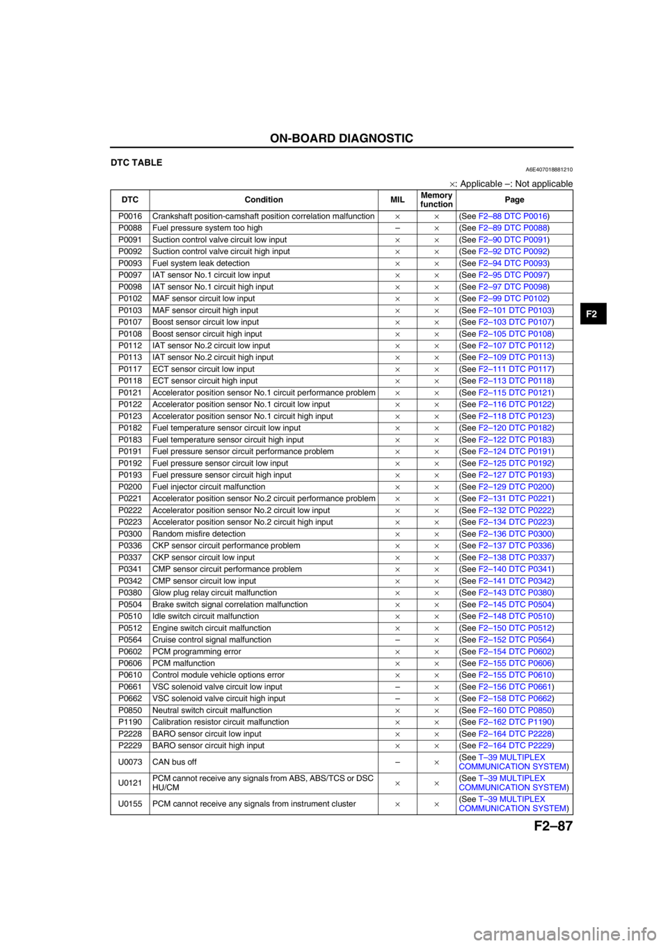
End Of SieDTC TABLEA6E407018881210
×: Applicable –: Not applicable
DTC Condition MILMemory
functionPage
P0016 Crankshaft position-camshaft position correlation malfunction××(See F2–88 DTC P0016)
P0088 Fuel pressure system too high–×(See F2–89 DTC P0088)
P0091 Suction control valve circuit low input××(See F2–90 DTC P0091)
P0092 Suction control valve circuit high input××(See F2–92 DTC P0092)
P0093 Fuel system leak detection××(See F2–94 DTC P0093)
P0097 IAT sensor No.1 circuit low input××(See F2–95 DTC P0097)
P0098 IAT sensor No.1 circuit high input××(See F2–97 DTC P0098)
P0102 MAF sensor circuit low input××(See F2–99 DTC P0102)
P0103 MAF sensor circuit high input××(See F2–101 DTC P0103)
P0107 Boost sensor circuit low input××(See F2–103 DTC P0107)
P0108 Boost sensor circuit high input××(See F2–105 DTC P0108)
P0112 IAT sensor No.2 circuit low input××(See F2–107 DTC P0112)
P0113 IAT sensor No.2 circuit high input××(See F2–109 DTC P0113)
P0117 ECT sensor circuit low input××(See F2–111 DTC P0117)
P0118 ECT sensor circuit high input××(See F2–113 DTC P0118)
P0121 Accelerator position sensor No.1 circuit performance problem××(See F2–115 DTC P0121)
P0122 Accelerator position sensor No.1 circuit low input××(See F2–116 DTC P0122)
P0123 Accelerator position sensor No.1 circuit high input××(See F2–118 DTC P0123)
P0182 Fuel temperature sensor circuit low input××(See F2–120 DTC P0182)
P0183 Fuel temperature sensor circuit high input××(See F2–122 DTC P0183)
P0191 Fuel pressure sensor circuit performance problem××(See F2–124 DTC P0191)
P0192 Fuel pressure sensor circuit low input××(See F2–125 DTC P0192)
P0193 Fuel pressure sensor circuit high input××(See F2–127 DTC P0193)
P0200 Fuel injector circuit malfunction××(See F2–129 DTC P0200)
P0221 Accelerator position sensor No.2 circuit performance problem××(See F2–131 DTC P0221)
P0222 Accelerator position sensor No.2 circuit low input××(See F2–132 DTC P0222)
P0223 Accelerator position sensor No.2 circuit high input××(See F2–134 DTC P0223)
P0300 Random misfire detection××(See F2–136 DTC P0300)
P0336 CKP sensor circuit performance problem××(See F2–137 DTC P0336)
P0337 CKP sensor circuit low input××(See F2–138 DTC P0337)
P0341 CMP sensor circuit performance problem××(See F2–140 DTC P0341)
P0342 CMP sensor circuit low input××(See F2–141 DTC P0342)
P0380 Glow plug relay circuit malfunction××(See F2–143 DTC P0380)
P0504 Brake switch signal correlation malfunction××(See F2–145 DTC P0504)
P0510 Idle switch circuit malfunction××(See F2–148 DTC P0510)
P0512 Engine switch circuit malfunction××(See F2–150 DTC P0512)
P0564 Cruise control signal malfunction–×(See F2–152 DTC P0564)
P0602 PCM programming error××(See F2–154 DTC P0602)
P0606 PCM malfunction××(See F2–155 DTC P0606)
P0610 Control module vehicle options error××(See F2–155 DTC P0610)
P0661 VSC solenoid valve circuit low input–×(See F2–156 DTC P0661)
P0662 VSC solenoid valve circuit high input–×(See F2–158 DTC P0662)
P0850 Neutral switch circuit malfunction××(See F2–160 DTC P0850)
P1190 Calibration resistor circuit malfunction××(See F2–162 DTC P1190)
P2228 BARO sensor circuit low input××(See F2–164 DTC P2228)
P2229 BARO sensor circuit high input××(See F2–164 DTC P2229)
U0073 CAN bus off–×(See T–39 MULTIPLEX
COMMUNICATION SYSTEM)
U0121PCM cannot receive any signals from ABS, ABS/TCS or DSC
HU/CM××(See T–39 MULTIPLEX
COMMUNICATION SYSTEM)
U0155 PCM cannot receive any signals from instrument cluster××(See T–39 MULTIPLEX
COMMUNICATION SYSTEM)
Page 347 of 909

TROUBLESHOOTING
F2–195
F2
NO.12 LACK/LOSS OF POWER-ACCELERATION/CRUISEA6E408018881214
Diagnostic Procedure
12 LACK/LOSS OF POWER-ACCELERATION CRUISE
DESCRIPTION•Performance is poor under load (e.g., power down when climbing hills).
POSSIBLE
CAUSE•Poor fuel quality
•Air leakage from intake-air system
•Intake-air system restriction or clogging
•Engine overheating
•A/C system improper operation
•Improper operation of A/C cut-off control
•Variable boost control (VBC) system malfunction
•Variable swirl control (VSC) system malfunction
•EGR system malfunction
•Vacuum leakage
•Clutch slippage
•Exhaust system and/or catalyst converter restriction
•Fuel line or clogging or restriction
•Fuel filter clogging or restriction
•Incorrect fuel injection timing
•Erratic signal from CKP sensor
•Erratic signal from CMP sensor
•ECT sensor or related circuit malfunction
•Boost sensor or related circuit malfunction
•Accelerator position sensor or related circuit malfunction
•Idle switch or related circuit malfunction
•MAF/IAT sensor or related circuit malfunction
•IAT sensor No.2 or related circuit malfunction
•Incorrect adjustment accelerator position sensor and/or idle switch
•Incorrect idle speed
•Inadequate fuel pressure
•Fuel pressure sensor or related circuit malfunction
•Suction control valve malfunction (built-in supply pump)
•Fuel pressure limiter malfunction (built-in common rail)
•Supply pump malfunction
•Fuel injector malfunction
•Low engine compression
•Improper valve timing
•Cooling fan No.1 or cooling fan No.2 seat are improper
•Turbocharger malfunction
•Charge air cooler malfunction
•Brake system dragging
•Intake shutter valve malfunction
•Guide blade valve malfunction
•IDM or related circuit malfunction
Warning
The following troubleshooting flow chart contains the fuel system diagnosis and repair
procedures. Read the following warnings before performing the fuel system services:
•Fuel vapor is hazardous. It can easily ignite, causing serious injury and damage. Always keep
sparks and flames away from fuel.
•Fuel line spills and leakage are dangerous. Fuel can ignite and cause serious injury or death
and damage. Fuel can also irritate skin and eyes. To prevent this, always complete “BEFORE
REPAIR PROCEDURE” and “AFTER REPAIR PROCEDURE” described in this manual.
STEP INSPECTION RESULTS ACTION
1 Is idle speed stable? Yes Go to next step.
No Go to symptom troubleshooting “NO.8 ENGINE RUNS
ROUGH/ROLLING IDLE”.
2 Is engine overheating? Yes Go to symptom troubleshooting “NO.17 COOLING
SYSTEM CONCERNS—OVERHEATING”.
No Go to next step.
Page 350 of 909
F2–198
TROUBLESHOOTING
End Of Sie
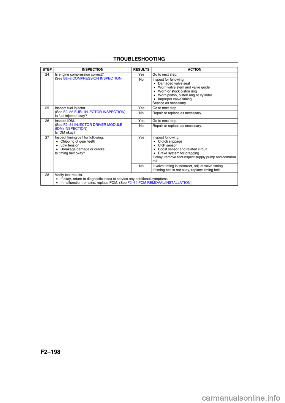
24 Is engine compression correct?
(See B2–8 COMPRESSION INSPECTION)Yes Go to next step.
No Inspect for following:
•Damaged valve seat
•Worn valve stem and valve guide
•Worn or stuck piston ring
•Worn piston, piston ring or cylinder
•Improper valve timing
Service as necessary.
25 Inspect fuel injector.
(See F2–56 FUEL INJECTOR INSPECTION)
Is fuel injector okay?Yes Go to next step.
No Repair or replace as necessary.
26 Inspect IDM.
(See F2–84 INJECTOR DRIVER MODULE
(IDM) INSPECTION)
Is IDM okay?Yes Go to next step.
No Repair or replace as necessary.
27 Inspect timing belt for following:
•Chipping of gear teeth
•Low tension
•Breakage damage or cracks
Is timing belt okay?Yes Inspect following:
•Clutch slippage
•CKP sensor
•Boost sensor and related circuit
•Brake system for dragging
If okay, remove and inspect supply pump and common
rail.
No If valve timing is incorrect, adjust valve timing.
If timing belt is not okay, replace timing belt.
28 Verify test results.
•If okay, return to diagnostic index to service any additional symptoms.
•If malfunction remains, replace PCM. (See F2–64 PCM REMOVAL/INSTALLATION) STEP INSPECTION RESULTS ACTION
Page 354 of 909

F2–202
TROUBLESHOOTING
NO.14 POOR FUEL ECONOMYA6E408018881216
Diagnostic Procedure
14 POOR FUEL ECONOMY
DESCRIPTION•Fuel economy is unsatisfactory.
POSSIBLE
CAUSE•Incorrect idle speed
•A/C system improper operation
•Intake -air system clogging or restriction
•Engine cooling system malfunction
•Poor fuel quality
•Improper coolant level
•Erratic signal from CKP sensor
•Erratic signal from CMP sensor
•Fuel pressure sensor or related circuit malfunction
•ECT sensor or related circuit malfunction
•Boost sensor or related circuit malfunction
•Accelerator position sensor or related circuit malfunction
•Incorrect adjustment idle switch
•MAF/IAT sensor or related circuit malfunction
•IAT sensor No .2 or related circuit malfunction
•VSS or related circuit malfunction
•Turbocharger malfunction
•Charge air cooler malfunction
•Low engine compression
•Improper valve timing
•Exhaust system and/or catalyst converter clogging
•Incorrect fuel injection timing
•Fuel injector malfunction
•Supply pump malfunction
•Fuel leakage
•Fuel line clogging or restriction
•Fuel filter clogging or restriction
•Brake dragging
•EGR system malfunction
•Vacuum leakage
•Clutch slippage
•Variable boost control (VBC) system malfunction
•Coolant heater system malfunction
Warning
The following troubleshooting flow chart contains the fuel system diagnosis and repair
procedures. Read the following warnings before performing the fuel system services:
•Fuel vapor is hazardous. It can easily ignite, causing serious injury and damage. Always keep
sparks and flames away from fuel.
•Fuel line spills and leakage are dangerous. Fuel can ignite and cause serious injury or death
and damage. Fuel can also irritate skin and eyes. To prevent this, always complete “BEFORE
REPAIR PROCEDURE” and “AFTER REPAIR PROCEDURE” described in this manual.
STEP INSPECTION RESULTS ACTION
1 Inspect for following:
•Fuel quality (e.g.: including water
contamination, winter/summer blend)
•Fuel line/fuel filter clogging and/or restriction
•Fuel line leakage
•Intake-air system restriction
•Exhaust system and/or catalyst converter
restriction
•Charge air cooler condition (restriction or
damaged)
•Vacuum leakage
Are all items okay?Yes Go to next step.
No Service as necessary.
Repeat Step 1.
2 Is brake system functioning properly? Yes Go to next step.
No Inspect for cause.
Page 356 of 909
F2–204
TROUBLESHOOTING
End Of Sie
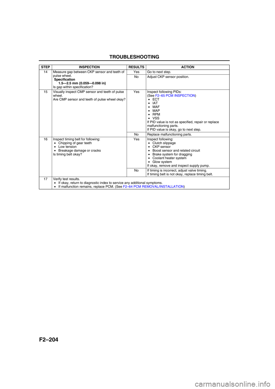
14 Measure gap between CKP sensor and teeth of
pulse wheel.
Specification
1.5—2.5 mm {0.059—0.098 in}
Is gap within specification?Yes Go to next step.
No Adjust CKP sensor position.
15 Visually inspect CMP sensor and teeth of pulse
wheel.
Are CMP sensor and teeth of pulse wheel okay?Yes Inspect following PIDs:
(See F2–65 PCM INSPECTION)
•ECT
•IAT
•MAF
•MAP
•RPM
•VSS
If PID value is not as specified, repair or replace
malfunctioning parts.
If PID value is okay, go to next step.
No Replace malfunctioning parts.
16 Inspect timing belt for following:
•Chipping of gear teeth
•Low tension
•Breakage damage or cracks
Is timing belt okay?Yes Inspect following:
•Clutch slippage
•CKP sensor
•Boost sensor and related circuit
•Brake system for dragging
•Coolant heater system
•Glow system
If okay, remove and inspect supply pump.
No If timing is incorrect, adjust valve timing.
If timing belt is not okay, replace timing belt.
17 Verify test results.
•If okay, return to diagnostic index to service any additional symptoms.
•If malfunction remains, replace PCM. (See F2–64 PCM REMOVAL/INSTALLATION) STEP INSPECTION RESULTS ACTION
Page 419 of 909

K2–4
AUTOMATIC TRANSAXLE
Bold frames:New specifications
End Of Sie
OUTLINEA6E571401030201•Adopted new JA5AX-EL automatic transaxle.
•Newly designed FF type five-speed automatic transaxle.
—Use of 3 sets of planetary gears, and a wider gear ratio setting realizes improvement of acceleration-from-
standing-start performance, fuel economy, and quietness. Also, by placement of two sets of planetary gears
in parallel with one set, the automatic transaxle is more compact.
•Adopted 2-4 brake clutch.
—Adopted a wet-type, multi-plate 2-4 brake clutch instead of the 2-4 brake band used in the past, for
smoother gear switching performance.
•Adopted centrifugal balance clutch
—The newly adopted centrifugal balance clutch pushes the clutch piston forcefully to low and high clutch by
centrifugal hydraulic pressure for smoother gear switching with batter response.
•Adopted controller area network (CAN)
—By adopting CAN, The TCM is always in contact with other computers in the car and controls the automatic
transaxle properly. This has also made troubleshooting diagnosis easier for the entire vehicle.
•Solenoid, sensor
—Adoption of four duty-type solenoids, five ON-OFF type solenoids, and three revolving sensors realizes
finer, more expedient control of gear shifting performance.
•Adoption of revers inhibit control
—If the reverse position is selected by mistake while driving in forward motion, the reverse inhibit control
system will cancel the operation electronically and set the position to neutral as a safety enhancement.
Outline of Operation
•The operation of the electronic automatic transaxle is classified into three systems: the electronic control
system, the hydraulic pressure control system, and the powertrain system (includes the torque converter
system.)
Electronic control system
•According to the signals from the switches and sensors in the input system, the TCM outputs the signal
which matches the present driving condition to the ON/OFF type solenoids and the duty-cycle type
solenoids in the hydraulic pressure control system.
Hydraulic pressure control system
•According to the signals from the TCM, each solenoid operates to switch the hydraulic passages in the
control valve body and controls the clutch engagement pressure.
•The line pressure is adjusted by the duty-cycle type pressure control solenoid. The hydraulic passages
are switched by the ON/OFF type solenoids and the clutch engagement pressure is controlled by the
duty-cycle type solenoids.
Powertrain system
•The driving force from the engine is transmitted through the torque converter to the transaxle.
•The transmitted driving force operates each clutch and brake according to the clutch engagement
pressure from the duty-cycle type solenoid, and the planetary gears change the gear ratio to the
optimal driving force. The changed driving force is transmitted through the differential to the axle shaft
and then the tires.
AUTOMATIC TRANSAXLE
Page 423 of 909
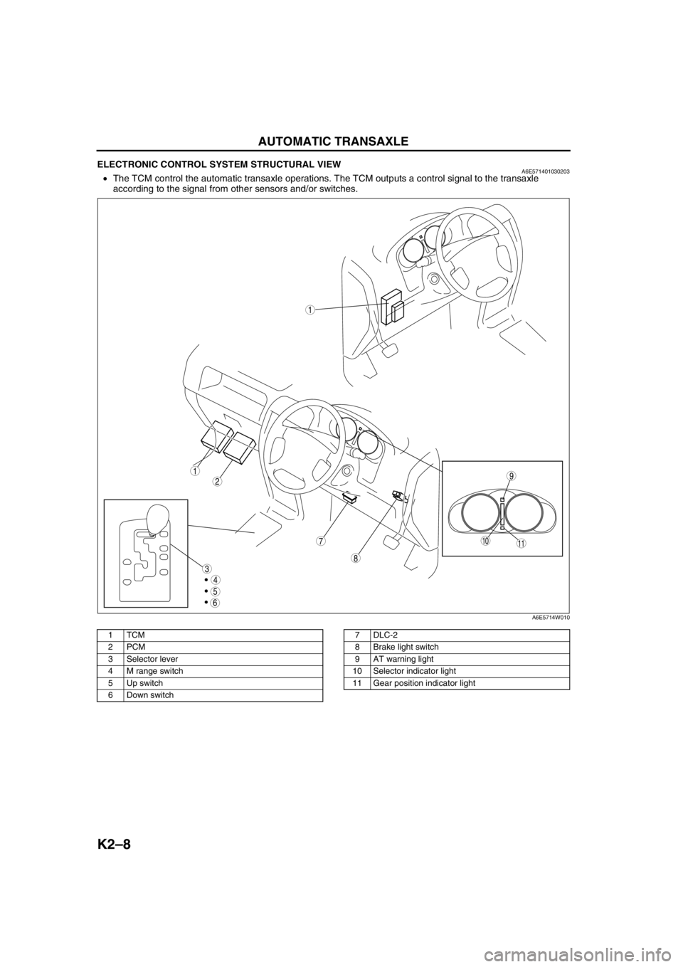
K2–8
AUTOMATIC TRANSAXLE
ELECTRONIC CONTROL SYSTEM STRUCTURAL VIEWA6E571401030203•The TCM control the automatic transaxle operations. The TCM outputs a control signal to the transaxle
according to the signal from other sensors and/or switches.
.
9
8
7
5
4
3
1
2
1011
6
1
A6E5714W010
1TCM
2PCM
3Selector lever
4 M range switch
5 Up switch
6 Down switch7DLC-2
8 Brake light switch
9 AT warning light
10 Selector indicator light
11 Gear position indicator light
Page 425 of 909
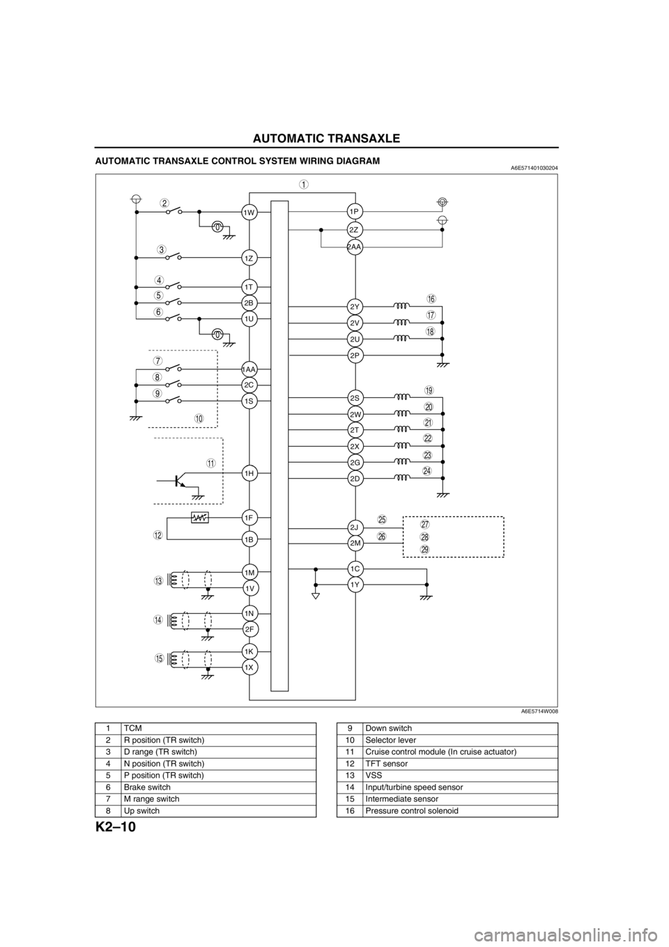
K2–10
AUTOMATIC TRANSAXLE
AUTOMATIC TRANSAXLE CONTROL SYSTEM WIRING DIAGRAMA6E571401030204
.
1W1P
2P
2S
2T
2X
2G
2D
2J
2M
1C
1Y 2W 2Z
2Y
2V
2U 1Z
1T
2B
1U
2C
1S
1H
1F
1B
1M
1V
1N
2F
1K
1X 1AA2AA
9
8
7
5
4
3
1
2
10
19
18
17
15
16
14
13
11
12
20
6
29
28
2725
26
24
23
21
22
A6E5714W008
1TCM
2 R position (TR switch)
3 D range (TR switch)
4 N position (TR switch)
5 P position (TR switch)
6 Brake switch
7 M range switch
8 Up switch9 Down switch
10 Selector lever
11 Cruise control module (In cruise actuator)
12 TFT sensor
13 VSS
14 Input/turbine speed sensor
15 Intermediate sensor
16 Pressure control solenoid
Page 426 of 909
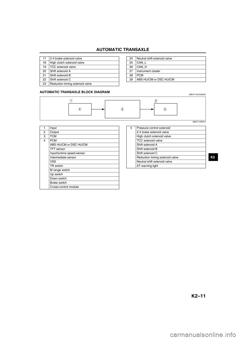
AUTOMATIC TRANSAXLE
K2–11
K2
End Of SieAUTOMATIC TRANSAXLE BLOCK DIAGRAMA6E571401030205
.
17 2-4 brake solenoid valve
18 High clutch solenoid valve
19 TCC solenoid valve
20 Shift solenoid A
21 Shift solenoid B
22 Shift solenoid C
23 Reduction timing solenoid valve24 Neutral shift solenoid valve
25 CAN_L
26 CAN_H
27 Instrument cluster
28 PCM
29 ABS HU/CM or DSC HU/CM
543
12
A6E5714W012
1 Input
2Output
3TCM
4PCM
ABS HU/CM or DSC HU/CM
TFT sensor
Input/turbine speed sensor
Intermediate sensor
VSS
TR switch
M range switch
Up switch
Down switch
Brake switch
Cruise control module5 Pressure control solenoid
2-4 brake solenoid valve
High clutch solenoid valve
TCC solenoid valve
Shift solenoid A
Shift solenoid B
Shift solenoid C
Reduction timing solenoid valve
Neutral shift solenoid valve
AT warning light