fuel cap MAZDA 6 2002 Workshop Manual Suplement
[x] Cancel search | Manufacturer: MAZDA, Model Year: 2002, Model line: 6, Model: MAZDA 6 2002Pages: 909, PDF Size: 17.16 MB
Page 90 of 909

F1–2
OUTLINE
OUTLINE OF CONSTRUCTIONA6E390218881201•The fuel and emission control systems are essentially carried over from the current Mazda6 (GG), except for
the following features. (See Mazda6 Training Manual 3359-1*-02C.)
End Of Sie
FEATURESA6E390218881202System simplification
•Controller area network has been adopted with TCM communication (4WD).
TCM adoption
•DTC for CAN (TCM communication) has been adopted.
Modifications to match the vehicle characteristics
•The idle speed has been modified.
•Fuel pump (transfer) has been adopted.
End Of Sie
SPECIFICATIONSA6E390218881203
*1: Without the BARO sensor
*2: With the BARO sensor
Bold frames: New specifications
End Of Sie
OUTLINE
Item 2WD 4WD
Air cleaner element Type Paper element (oil permeated)
IAC valve Type Duty control
Fuel injectorType Hi-ohmic
Type of fuel delivery Top-feed
Type of drive Voltage
Pressure regulatorRegulating pressure
(kPa {kgf/cm
2, psi})440 {4.5, 64}
Fuel tankCapacity
(L {US qt, lmp qt})64 {68, 56} 62 {65, 54}
Fuel SpecificationUnleaded
(RON 90*
1/95*2 or above)Unleaded (RON 95 or above)
Catalyst Type TWC (monolythic)
EGR control Type Stepping motor type
Evaporative emission control
systemType Canister type
PCV system Type Closed type
Page 97 of 909

FUEL SYSTEM
F1–9
F1
End Of Sie
OUTLINEA6E391201006201•The fuel system is essentially carried over from that of the current Mazda6 (GG), except for the following. (See
Mazda6 Training Manual 3359-1*-02C.)
—A saddle type fuel tank has been adopted.
—A fuel pump (transfer) for fuel transmission has been added.
End Of Sie
STRUCTURAL VIEWA6E391201006202
.
End Of Sie
FUEL SYSTEM
7
5
4
3
6
1
2
A6E39122001
1 Fuel gauge sender sub-unit
2 Quick release connector (fuel tank side, transfer
hose part)
3 Non-return valve4 Quick release connector (fuel tank side, main fuel
pipe part)
5 Fuel tank
6 Fuel pump unit
7 Filler cap
Page 98 of 909

F1–10
FUEL SYSTEM
SYSTEM DIAGRAMA6E391201006203
.
End Of Sie
FUEL PUMP (TRANSFER)A6E391213350201Function
•The fuel tank for 4WD is saddle type. Fuel in the fuel gauge sender sub-unit side (right side) is pumped to the
left side of the fuel tank using the fuel pump (transfer).
Structure
•The fuel pump (transfer) is integrated into the fuel pump unit and it cannot be separately disassembled.
•The fuel pump (transfer) is composed of a relief valve and fuel jet pump.
87
5
4
3
6
1
2
:
9
10
A6E39122002
1 Filler cap
2 Pressure regulator
3 Fuel pump (transfer)
4 Fuel filter (high-pressure)
5Fuel pump6 Fuel filter (low-pressure)
7 Fuel pump unit
8 Pulsation damper
9 Fuel injector
10 Fuel flow
Page 112 of 909

F1–24
FUEL SYSTEM
10. Remove in the order indicated in the table.
11. Install in the reverse order of removal.
12. Complete the “AFTER REPAIR PROCEDURE”.
.
44—60
{4.5—6.1, 33—44}
7
5
4
3
2
1
6
A
N·m {kgf·m, ft·lbf} 44—60
{4.5—6.1, 33—44}
44—60
{4.5—6.1, 33—44}8.9—12.7 N·m
{91—120 kgf·cm, 79—110 in·lbf}
8.9—12.7 N·m
{91—120 kgf·cm, 79—110 in·lbf}
A6E39122008
1 Joint hose
(See F1–25 Joint Hose Installation Note)
2 Breather hose
(See F1–25 Breather Hose Installation Note)
3 Evaporative hose
(See F1–25 Evaporative Hose Installation Note)4 Fuel tank
5 Fuel-filler pipe
6 C-ring
7 Filler cap
Page 114 of 909

F1–26
FUEL SYSTEM
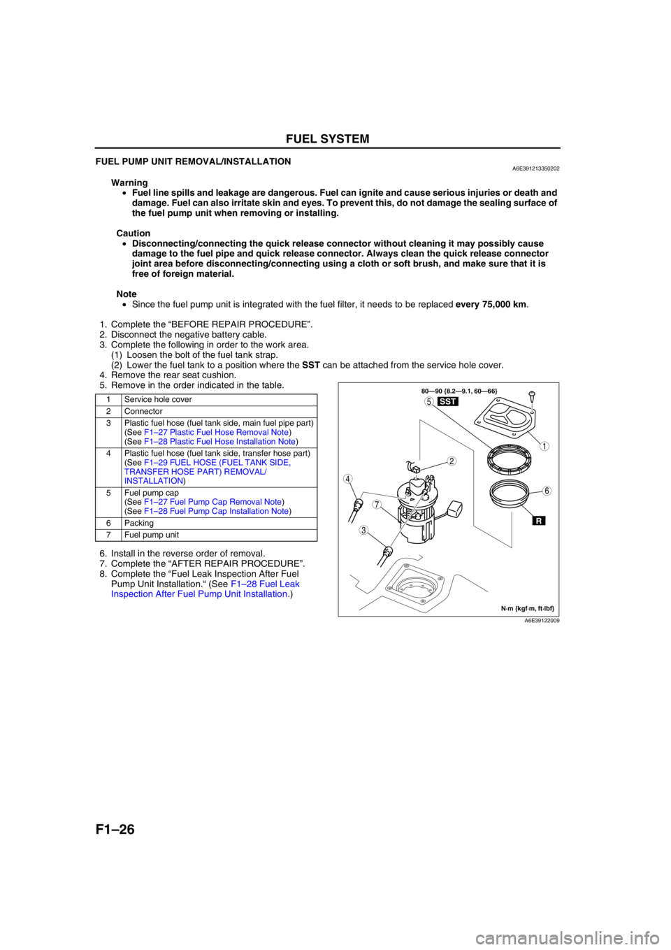
FUEL PUMP UNIT REMOVAL/INSTALLATIONA6E391213350202
Warning
•Fuel line spills and leakage are dangerous. Fuel can ignite and cause serious injuries or death and
damage. Fuel can also irritate skin and eyes. To prevent this, do not damage the sealing surface of
the fuel pump unit when removing or installing.
Caution
•Disconnecting/connecting the quick release connector without cleaning it may possibly cause
damage to the fuel pipe and quick release connector. Always clean the quick release connector
joint area before disconnecting/connecting using a cloth or soft brush, and make sure that it is
free of foreign material.
Note
•Since the fuel pump unit is integrated with the fuel filter, it needs to be replaced every 75,000 km.
1. Complete the “BEFORE REPAIR PROCEDURE”.
2. Disconnect the negative battery cable.
3. Complete the following in order to the work area.
(1) Loosen the bolt of the fuel tank strap.
(2) Lower the fuel tank to a position where the SST can be attached from the service hole cover.
4. Remove the rear seat cushion.
5. Remove in the order indicated in the table.
.
6. Install in the reverse order of removal.
7. Complete the “AFTER REPAIR PROCEDURE”.
8. Complete the “Fuel Leak Inspection After Fuel
Pump Unit Installation.“ (See F1–28 Fuel Leak
Inspection After Fuel Pump Unit Installation.)
1 Service hole cover
2 Connector
3 Plastic fuel hose (fuel tank side, main fuel pipe part)
(See F1–27 Plastic Fuel Hose Removal Note)
(See F1–28 Plastic Fuel Hose Installation Note)
4 Plastic fuel hose (fuel tank side, transfer hose part)
(See F1–29 FUEL HOSE (FUEL TANK SIDE,
TRANSFER HOSE PART) REMOVAL/
INSTALLATION)
5Fuel pump cap
(See F1–27 Fuel Pump Cap Removal Note)
(See F1–28 Fuel Pump Cap Installation Note)
6 Packing
7 Fuel pump unit
3
7
1
4
5
2
6
80—90 {8.2—9.1, 60—66}
R
SST
N·m {kgf·m, ft·lbf}
A6E39122009
Page 115 of 909

FUEL SYSTEM
F1–27
F1
Plastic Fuel Hose Removal Note
Caution
•The quick release connector may be damaged if the tab is bent excessively. Do not expand the tab
over the stopper.
1. Disconnect the quick release connector.
(1) Push the tab on the locking coupler 90
degrees until it stops.
(2) Pull the fuel hose straight back.
Note
•The stopper may be removed from the quick
connector. Take care not to lose it.
Reinstall it to the quick release connector
before reconnecting the fuel line.
•The locking coupler has two internal locking
tabs which retain the fuel pipe. Be sure that
the tab on the locking coupler is rotated until
it stops to release two internal locking tabs.
2. Cover the disconnected quick release connector
and fuel pipe with vinyl sheets or the like to
prevent them from being scratched or
contaminated with foreign material.
Fuel Pump Cap Removal Note
1. Using the SST, remove the fuel pump cap.
FUEL PIPE
STOPPER TAB
A6E3912W001
LOCKING TAB
A6E3912W002
A6E39122015
49 T042 001A
A6E39122012
Page 116 of 909

F1–28
FUEL SYSTEM
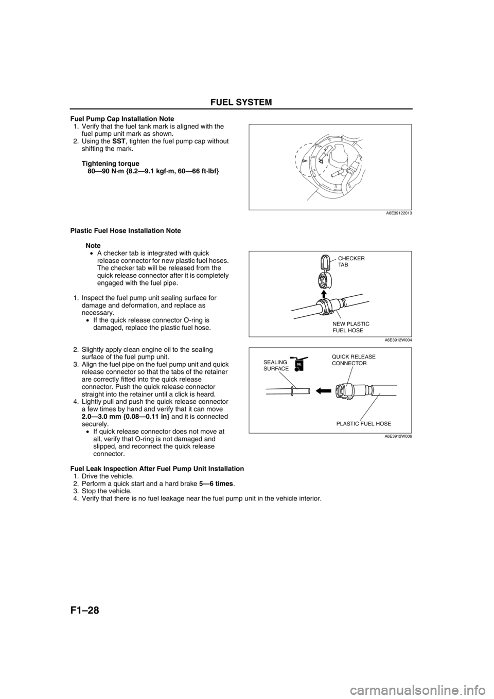
Fuel Pump Cap Installation Note
1. Verify that the fuel tank mark is aligned with the
fuel pump unit mark as shown.
2. Using the SST, tighten the fuel pump cap without
shifting the mark.
Tightening torque
80—90 N·m {8.2—9.1 kgf·m, 60—66 ft·lbf}
Plastic Fuel Hose Installation Note
Note
•A checker tab is integrated with quick
release connector for new plastic fuel hoses.
The checker tab will be released from the
quick release connector after it is completely
engaged with the fuel pipe.
1. Inspect the fuel pump unit sealing surface for
damage and deformation, and replace as
necessary.
•If the quick release connector O-ring is
damaged, replace the plastic fuel hose.
2. Slightly apply clean engine oil to the sealing
surface of the fuel pump unit.
3. Align the fuel pipe on the fuel pump unit and quick
release connector so that the tabs of the retainer
are correctly fitted into the quick release
connector. Push the quick release connector
straight into the retainer until a click is heard.
4. Lightly pull and push the quick release connector
a few times by hand and verify that it can move
2.0—3.0 mm {0.08—0.11 in} and it is connected
securely.
•If quick release connector does not move at
all, verify that O-ring is not damaged and
slipped, and reconnect the quick release
connector.
Fuel Leak Inspection After Fuel Pump Unit Installation
1. Drive the vehicle.
2. Perform a quick start and a hard brake 5—6 times.
3. Stop the vehicle.
4. Verify that there is no fuel leakage near the fuel pump unit in the vehicle interior.
End Of Sie
A6E39122013
CHECKER
TA B
NEW PLASTIC
FUEL HOSE
A6E3912W004
OILOIL
PLASTIC FUEL HOSE QUICK RELEASE
CONNECTOR SEALING
SURFACE
A6E3912W006
Page 155 of 909

OUTLINE
F2–3
F2
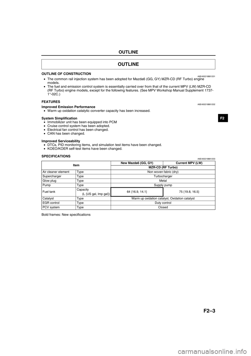
OUTLINE OF CONSTRUCTIONA6E400218881201•The common rail injection system has been adopted for Mazda6 (GG, GY) MZR-CD (RF Turbo) engine
models.
•The fuel and emission control system is essentially carried over from that of the current MPV (LW) MZR-CD
(RF Turbo) engine models, except for the following features. (See MPV Workshop Manual Supplement 1737-
1*-02C.)
End Of Sie
FEATURESA6E400218881202Improved Emission Performance
•Warm up oxidation catalytic converter capacity has been increased.
System Simplification
•Immobilizer unit has been equipped into PCM
•Cruise control system has been adopted.
•Electrical fan control has been changed.
•CAN has been changed.
Improved Serviceability
•DTCs, PID monitoring items, and simulation test items have been changed.
•KOEO/KOER self-test items have been changed.
End Of Sie
SPECIFICATIONSA6E400218881203
Bold frames: New specifications
End Of Sie
OUTLINE
ItemNew Mazda6 (GG, GY) Current MPV (LW)
MZR-CD (RF Turbo)
Air cleaner element Type Non woven fabric (dry)
Supercharger Type Turbocharger
Glow plug Type Metal
Pump Type Supply pump
Fuel tankCapacity
64 {16.9, 14.1} 75 {19.8, 16.5}
(L {US gal, lmp gal})
Catalyst Type Warm up oxidation catalyst, Oxidation catalyst
EGR control Type Duty control
PCV system Type Closed
Page 164 of 909

F2–12
FUEL SYSTEM
Fuel tank side
.
End Of Sie
4
31
2
A6E40122032
1 Fuel tank
2Fuel pump3 Nonreturn valve
4 Fuel filler cap
Page 168 of 909

F2–16
EMISSION SYSTEM, CONTROL SYSTEM
End Of SieWARM UP OXIDATION CATALYTIC CONVERTER DESCRIPTIONA6E401601007203•The warm up oxidation catalytic converter capacity has been increased to 1,920 ml {1,920 cc, 117 cu in} in
order to improve emission performance.
End Of Sie
OUTLINEA6E404018881201•The control system is essentially carried over from that of the current MPV (LW) MZR-CD (RF Turbo) engine
models. (See MPV Workshop Manual Supplement 1737-1*-02C.)
Input Device
×:Applicable –: Not applicable
CONTROL SYSTEM
ItemMazda6
(GG, GY)Current
MPV (LW)
Remark for new model
MZR-CD (RF Turbo)
Battery×Same function as MPV (LW) MZR-CD (RF Turbo) engine model
Starter (starter signal)×Same function as MPV (LW) MZR-CD (RF Turbo) engine model
Starter relay×–Newly adopted
Clutch switch×Same function as MPV (LW) MZR-CD (RF Turbo) engine model
Neutral switch×Same function as MPV (LW) MZR-CD (RF Turbo) engine model
Brake switch×Same function as Mazda6 (GG) L series engine model
Idle switch×Same function as MPV (LW) MZR-CD (RF Turbo) engine model
A/C switch×Same function as MPV (LW) MZR-CD (RF Turbo) engine model
Refrigerant pressure switch×Same function as 626 (GF, GW) RF Turbo engine model
Cruise control switch×Same function as Mazda6 (GG) L series engine model
Accelerator position sensor×Same function as MPV (LW) MZR-CD (RF Turbo) engine model
MAF/IAT sensor×Same function as MPV (LW) MZR-CD (RF Turbo) engine model
IAT sensor No.2×Same function as MPV (LW) MZR-CD (RF Turbo) engine model
ECT sensor×Same function as MPV (LW) MZR-CD (RF Turbo) engine model
Fuel temperature sensor×Same function as MPV (LW) MZR-CD (RF Turbo) engine model
BARO sensor (integrated in PCM)×Same function as MPV (LW) MZR-CD (RF Turbo) engine model
Boost sensor×Same function as MPV (LW) MZR-CD (RF Turbo) engine model
Fuel pressure sensor×Same function as MPV (LW) MZR-CD (RF Turbo) engine model
CMP sensor×Same function as MPV (LW) MZR-CD (RF Turbo) engine model
CKP sensor×Same function as MPV (LW) MZR-CD (RF Turbo) engine model
VSS×Vehicle speed signal is received by CAN
Calibration resistor×Same function as MPV (LW) MZR-CD (RF Turbo) engine model
Immobilizer unit (integrated in
PCM)×Immobilizer unit equipped into PCM