stop start MAZDA 6 2002 Workshop Manual Suplement
[x] Cancel search | Manufacturer: MAZDA, Model Year: 2002, Model line: 6, Model: MAZDA 6 2002Pages: 909, PDF Size: 17.16 MB
Page 71 of 909
OIL PRESSURE INSPECTION
D–7
D
OIL PRESSURE INSPECTIONA6E331001003201MZR-CD (RF Turbo)
Warning
•Continuous exposure to USED engine oil has caused skin cancer in laboratory mice. Protect your
skin by washing with soap and water immediately after working with engine oil.
•Hot engines and engine oil can cause severe burns. Turn off the engine and wait until it and the
engine oil have cooled.
1. Disconnect the negative battery cable.
2. Remove the under cover.
3. Remove the oil pressure switch.
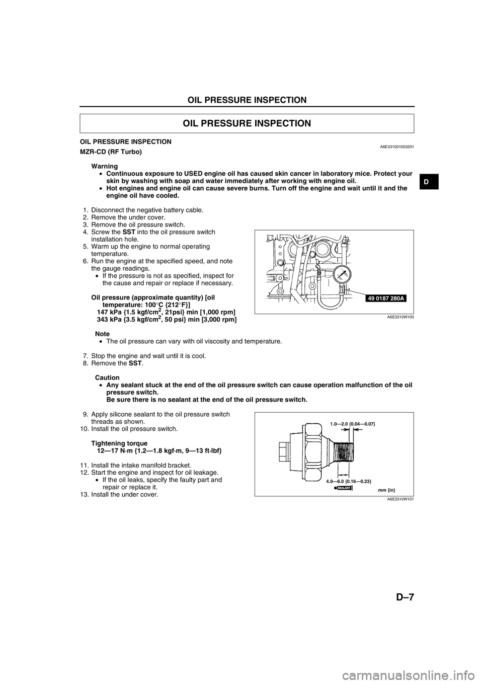
4. Screw the SST into the oil pressure switch
installation hole.
5. Warm up the engine to normal operating
temperature.
6. Run the engine at the specified speed, and note
the gauge readings.
•If the pressure is not as specified, inspect for
the cause and repair or replace if necessary.
Oil pressure (approximate quantity) [oil
temperature: 100°C {212°F}]
147 kPa {1.5 kgf/cm
2, 21psi} min [1,000 rpm]
343 kPa {3.5 kgf/cm2, 50 psi} min [3,000 rpm]
Note
•The oil pressure can vary with oil viscosity and temperature.
7. Stop the engine and wait until it is cool.
8. Remove the SST.
Caution
•Any sealant stuck at the end of the oil pressure switch can cause operation malfunction of the oil
pressure switch.
Be sure there is no sealant at the end of the oil pressure switch.
9. Apply silicone sealant to the oil pressure switch
threads as shown.
10. Install the oil pressure switch.
Tightening torque
12—17 N·m {1.2—1.8 kgf·m, 9—13 ft·lbf}
11. Install the intake manifold bracket.
12. Start the engine and inspect for oil leakage.
•If the oil leaks, specify the faulty part and
repair or replace it.
13. Install the under cover.
End Of Sie
OIL PRESSURE INSPECTION
49 0187 280A
A6E3310W100
1.0—2.0 {0.04—0.07}
4.0—6.0 {0.16—0.23}
mm {in}
SEALANTSEALANT
A6E3310W101
Page 72 of 909
D–8
ENGINE OIL
ENGINE OIL INSPECTIONA6E331214001201MZR-CD (RF Turbo)
1. Position the vehicle on level ground.
2. Warm up the engine to normal operating temperature.
3. Stop the engine and wait for 5 min.
4. Verify that the oil level is between the L and F marks on the dipstick and check the engine oil condition.
•If the oil level is below the L mark, add engine oil. (See D–8 ENGINE OIL REPLACEMENT.)
End Of SieENGINE OIL REPLACEMENTA6E331214001202MZR-CD (RF Turbo)
Warning
•Hot engines and engine oil can cause severe burns. Turn off the engine and wait until it and the
engine oil have cooled.
•A vehicle that is lifted but not securely supported on safety stands is dangerous. It can slip or fall,
causing death or serious injury. Never work around or under a lifted vehicle if it is not securely
supported on safety stands.
•Continuous exposure to USED engine oil has caused skin cancer in laboratory mice. Protect your
skin by washing with soap and water immediately after working with engine oil.
Caution
•In case you spill engine oil on the front pipe, wipe it off completely. If you fail to wipe the spilled
oil, it will produce fumes because of the heat.
1. Position the vehicle on level ground.
2. Remove the the oil filler cap.
3. Remove the under cover.
4. Remove the oil pan drain plug.
5. Drain the engine oil into a container.
6. Install the oil pan drain plug with a new the washer.
Tightening torque
12—17 N·m {1.2—1.8 kgf·m, 9—13 ft·lbf}
Note
•The amount of residual oil in the engine can vary with the replacement method, oil temperature, etc. Verify
the oil level after engine oil replacement.
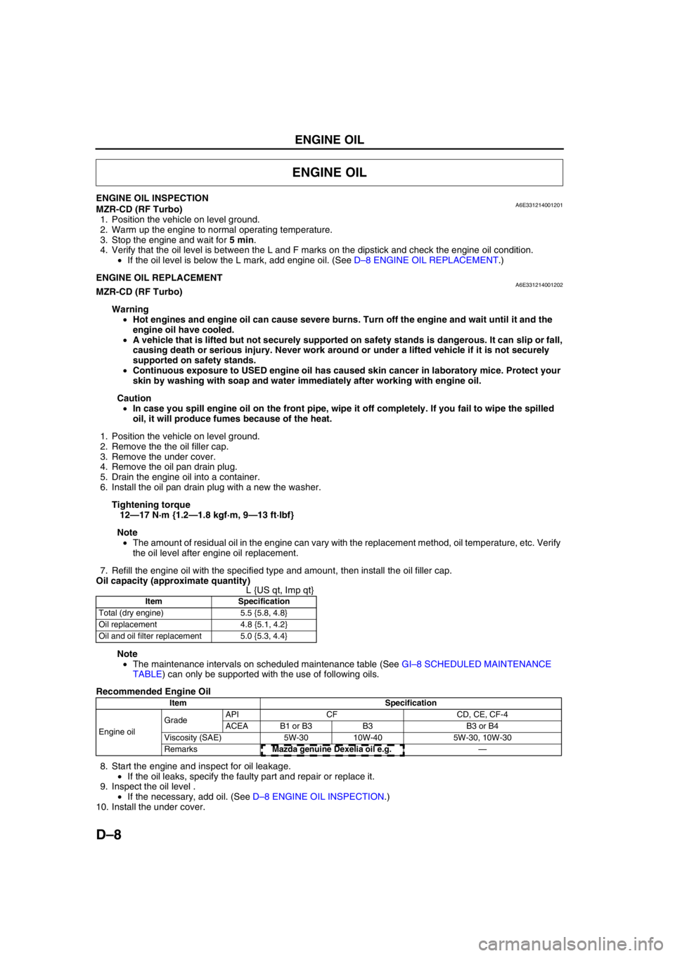
7. Refill the engine oil with the specified type and amount, then install the oil filler cap.
Oil capacity (approximate quantity)
L {US qt, Imp qt}
Note
•The maintenance intervals on scheduled maintenance table (See GI–8 SCHEDULED MAINTENANCE
TABLE) can only be supported with the use of following oils.
Recommended Engine Oil
8. Start the engine and inspect for oil leakage.
•If the oil leaks, specify the faulty part and repair or replace it.
9. Inspect the oil level .
•If the necessary, add oil. (See D–8 ENGINE OIL INSPECTION.)
10. Install the under cover.
End Of Sie
ENGINE OIL
Item Specification
Total (dry engine) 5.5 {5.8, 4.8}
Oil replacement 4.8 {5.1, 4.2}
Oil and oil filter replacement 5.0 {5.3, 4.4}
Item Specification
Engine oil GradeAPI CF CD, CE, CF-4
ACEA B1 or B3 B3 B3 or B4
Viscosity (SAE) 5W-30 10W-40 5W-30, 10W-30
RemarksMazda genuine Dexelia oil e.g. —
Page 110 of 909

F1–22
OUTLINE, ENGINE TUNE-UP
SUPPLEMENTAL SERVICE INFORMATIONA6E390218881206•The following changes and/or additions have been made since publication of the Mazda6 Workshop Manual
(1621-10-98E).
Idle speed
•Adjustment procedure has been modified.
Fuel tank
•Removal/installation procedure has been modified.
Fuel pump unit
•Removal/installation procedure has been modified.
Quick release connector (fuel tank side, transfer hose part)
•Removal/installation procedure has been added.
Exhaust system
•Removal/installation procedure has been modified.
PCM
•Inspection procedure has been modified.
On-board diagnostic
•Inspection procedure has been modified.
Troubleshooting
•Inspection procedure has been modified.
End Of Sie
IDLE SPEED INSPECTION (4WD)A6E390802000201
Note
•Ignition timing is not adjustable.
•Ignition timing verification requires WDS or equivalent.
1. Turn off the electrical loads.
2. Warm up the engine as follows.
(1) Start the engine.
(2) Maintain the engine speed at approx. 3,000 rpm until the cooling fans start to operate.
(3) Release the accelerator pedal.
(4) Wait until the cooling fans stop.
3. Verify that the idle speed (WDS: RPM PID) is within the specification using WDS or equivalent.
Idle speed
*1 : Excludes temporary idle speed drop just after the electrical loads are turned on.
*2 : Blower motor is operating at high speed. Headlight switch is turned on. Rear window defroster switch is turned
on. Cooling fans are operating.
End Of Sie
OUTLINE
ENGINE TUNE-UP
Condition
Engine speed (rpm)*1
No load 650—750
Electrical loads*
2 ON650—750
P/S ON 650—750
A/C ON and refrigerant
pressure switch (middle) OFF650—750
A/C ON and refrigerant
pressure switch (middle) ON700—800
Page 116 of 909
F1–28
FUEL SYSTEM
Fuel Pump Cap Installation Note
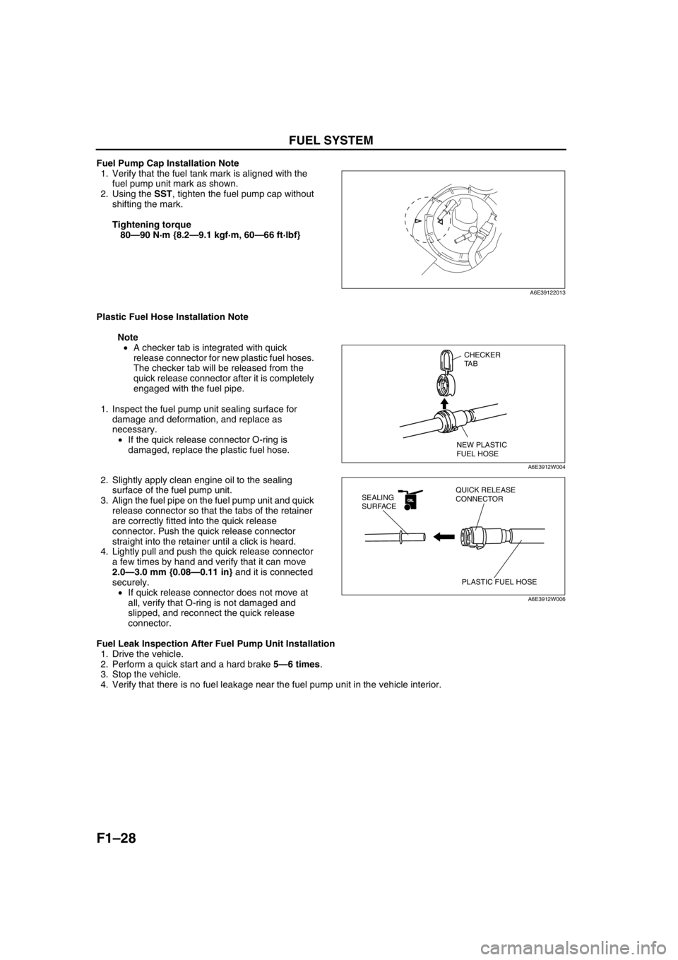
1. Verify that the fuel tank mark is aligned with the
fuel pump unit mark as shown.
2. Using the SST, tighten the fuel pump cap without
shifting the mark.
Tightening torque
80—90 N·m {8.2—9.1 kgf·m, 60—66 ft·lbf}
Plastic Fuel Hose Installation Note
Note
•A checker tab is integrated with quick
release connector for new plastic fuel hoses.
The checker tab will be released from the
quick release connector after it is completely
engaged with the fuel pipe.
1. Inspect the fuel pump unit sealing surface for
damage and deformation, and replace as
necessary.
•If the quick release connector O-ring is
damaged, replace the plastic fuel hose.
2. Slightly apply clean engine oil to the sealing
surface of the fuel pump unit.
3. Align the fuel pipe on the fuel pump unit and quick
release connector so that the tabs of the retainer
are correctly fitted into the quick release
connector. Push the quick release connector
straight into the retainer until a click is heard.
4. Lightly pull and push the quick release connector
a few times by hand and verify that it can move
2.0—3.0 mm {0.08—0.11 in} and it is connected
securely.
•If quick release connector does not move at
all, verify that O-ring is not damaged and
slipped, and reconnect the quick release
connector.
Fuel Leak Inspection After Fuel Pump Unit Installation
1. Drive the vehicle.
2. Perform a quick start and a hard brake 5—6 times.
3. Stop the vehicle.
4. Verify that there is no fuel leakage near the fuel pump unit in the vehicle interior.
End Of Sie
A6E39122013
CHECKER
TA B
NEW PLASTIC
FUEL HOSE
A6E3912W004
OILOIL
PLASTIC FUEL HOSE QUICK RELEASE
CONNECTOR SEALING
SURFACE
A6E3912W006
Page 141 of 909
ON-BOARD DIAGNOSTIC
F1–53
F1
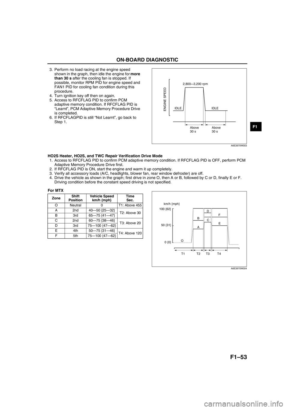
3. Perform no load racing at the engine speed
shown in the graph, then idle the engine for more
than 30 s after the cooling fan is stopped. If
possible, monitor RPM PID for engine speed and
FAN1 PID for cooling fan condition during this
procedure.
4. Turn ignition key off then on again.
5. Access to RFCFLAG PID to confirm PCM
adaptive memory condition. If RFCFLAG PID is
“Learnt”, PCM Adaptive Memory Procedure Drive
is completed.
6. If RFCFLAGPID is still “Not Learnt”, go back to
Step 1.
HO2S Heater, HO2S, and TWC Repair Verification Drive Mode
1. Access to RFCFLAG PID to confirm PCM adaptive memory condition. If RFCFLAG PID is OFF, perform PCM
Adaptive Memory Procedure Drive first.
2. If RFCFLAG PID is ON, start the engine and warm it up completely.
3. Verify all accessory loads (A/C, headlights, blower fan, rear window defroster) are off.
4. Drive the vehicle as shown in the graph; first drive in zone O, then A or B, followed by C or D, finally E or F.
Driving condition before the constant speed driving is not specified.
For MTX
2,800—3,200 rpm
IDLE
Above
30 sAbove
30 s
ENGINE SPEEDIDLE
A6E3970W003
ZoneShift
PositionVehicle Speed
km/h {mph}Time
Sec.
O Neutral 0 T1: Above 455
A2nd40—50 {25—32}
T2: Above 30
B3rd65—75 {41—47}
C2nd60—75 {38—46}
T3: Above 20
D3rd75—100 {47—62}
E4th50—75 {31—46}
T4: Above 120
F5th75—100 {47—62}
km/h {mph}
100 {62}
50 {31}
0 {0}O
T1 T2 T3 T4A BD
C
E F
A6E3970W004
Page 145 of 909

TROUBLESHOOTING
F1–57
F1
ENGINE SYMPTOM TROUBLESHOOTINGA6E398018881201•Confirm trouble symptom using the following diagnostic index, then go to appropriate troubleshooting chart.
Diagnostic Index
End Of Sie
TROUBLESHOOTING
No. TROUBLESHOOTING ITEM DESCRIPTION
1 Melting of main or other fuses—
2 MIL illuminates MIL is illuminated incorrectly.
3 Will not crank Starter does not work.
4Hard to start/long crank/erratic start/erratic
crankStarter cranks engine at normal speed but engine requires excessive
cranking time before starting.
5 Engine stalls. After start/at idle Engine stops unexpectedly at idle and/or after start.
6 Cranks normally but will not start Starter cranks engine at normal speed but engine will not run.
7 Slow return to idle Engine takes more time than normal to return to idle speed.
8 Engine runs rough/rolling idleEngine speed fluctuates between specified idle speed and lower
speed and engine shakes excessively.
9 Fast idle/runs onEngine speed continues at fast idle after warm-up.
Engine runs after ignition switch is turned to off.
10 Low idle/stalls during decelerationEngine stops unexpectedly at beginning of deceleration or recovery
from deceleration.
11Engine stalls/quits. Acceleration/cruiseEngine stops unexpectedly at beginning of acceleration or during
acceleration.
Engine stops unexpectedly while cruising.
Engine runs rough. Acceleration/cruise Engine speed fluctuates during acceleration or cruising.
Misses Acceleration/cruise Engine misses during acceleration or cruising.
Buck/jerkAcceleration/cruise/
decelerationVehicle bucks/jerks during acceleration, cruising, or deceleration.
Hesitation/stumble Acceleration Momentary pause at beginning of acceleration or during acceleration
Surges Acceleration/cruise Momentary minor irregularity in engine output
12 Lack/loss of power Acceleration/cruisePerformance is poor under load.
(e.g., power down when climbing hills)
13 Knocking/pinging Acceleration/cruiseSound is produced when air/fuel mixture is ignited by something other
than spark plug. (e.g., hot spot in combustion chamber)
14 Poor fuel economy Fuel economy is unsatisfactory.
15 Emission compliance Fails emissions test.
16 High oil consumption/leakage Oil consumption is excessive.
17Cooling system
concernsOverheating Engine runs at higher than normal temperature/overheats.
18Cooling system
concernsRuns cold Engine does not reach normal operating temperature.
19 Exhaust smoke Blue, black, or white smoke from exhaust system
20 Fuel odor (in engine compartment) Gasoline fuel smell or visible leakage
21 Engine noise Engine noise from under hood
22 Vibration concerns (engine) Vibration from under hood or driveline
23 A/C does not work sufficiently.A/C compressor magnetic clutch does not engage when A/C is turned
on.
24A/C is always on or A/C compressor runs
continuously.A/C compressor magnetic clutch does not disengage.
25 A/C is not cut off under WOT conditions. A/C compressor magnetic clutch does not disengage under WOT.
26 Exhaust sulphur smell Rotten egg smell (sulphur) from exhaust
27 Constant voltage Incorrect constant voltage
28 Spark plug condition Incorrect spark plug condition
29 ATX concernsUpshift/downshift/
engagementATX concerns not related to engine performance
Page 186 of 909
F2–34
ENGINE TUNE-UP
ENGINE TUNE-UP PREPARATIONA6E4008020002011. Start the engine and warm up completely.
2. Verify that the gear is in neutral position.
3. Verify that the accelerator pedal is released.
4. Turn off the A/C switch.
5. Turn off all electrical loads.
6. Verify that no DTC is present.
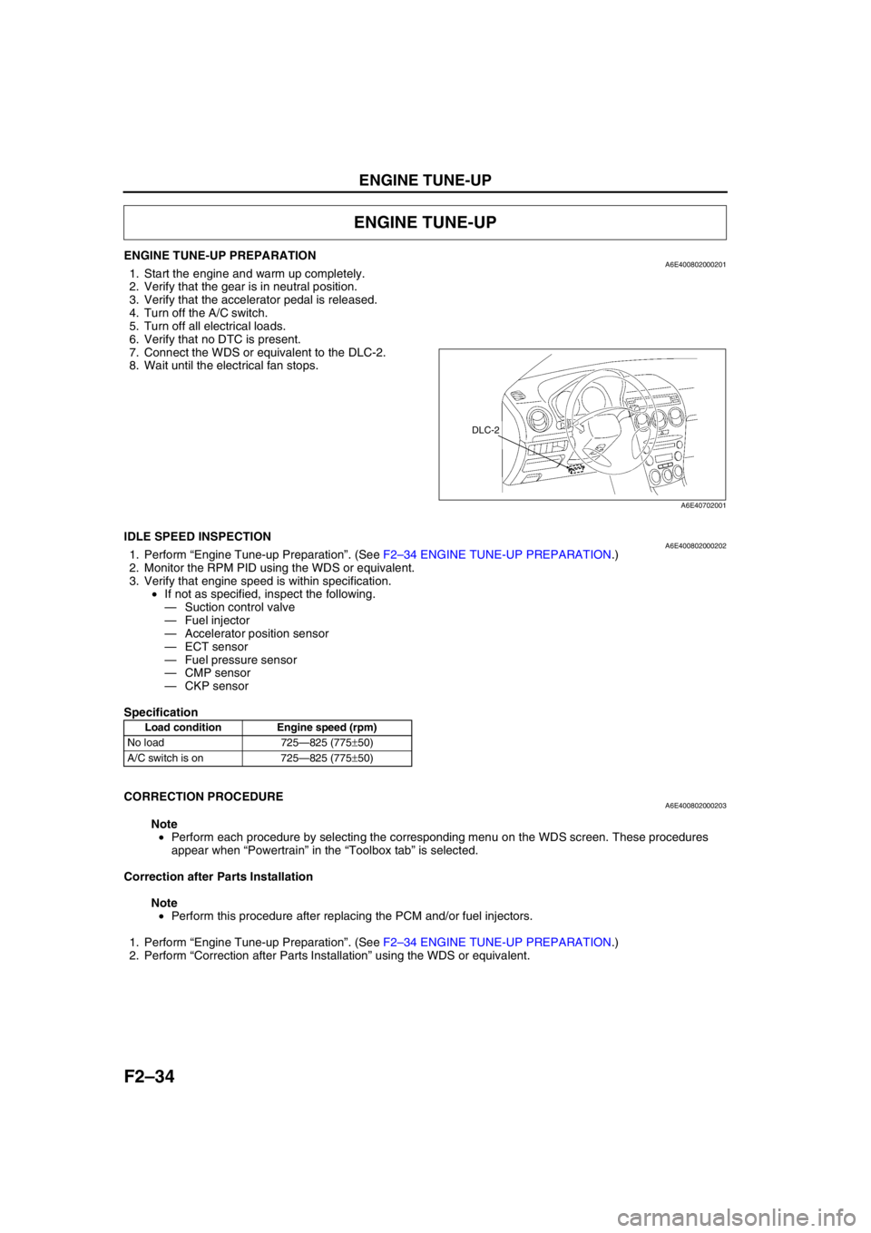
7. Connect the WDS or equivalent to the DLC-2.
8. Wait until the electrical fan stops.
End Of Sie
IDLE SPEED INSPECTIONA6E4008020002021. Perform “Engine Tune-up Preparation”. (See F2–34 ENGINE TUNE-UP PREPARATION.)
2. Monitor the RPM PID using the WDS or equivalent.
3. Verify that engine speed is within specification.
•If not as specified, inspect the following.
—Suction control valve
—Fuel injector
—Accelerator position sensor
—ECT sensor
—Fuel pressure sensor
—CMP sensor
—CKP sensor
Specification
End Of Sie
CORRECTION PROCEDUREA6E400802000203
Note
•Perform each procedure by selecting the corresponding menu on the WDS screen. These procedures
appear when “Powertrain” in the “Toolbox tab” is selected.
Correction after Parts Installation
Note
•Perform this procedure after replacing the PCM and/or fuel injectors.
1. Perform “Engine Tune-up Preparation”. (See F2–34 ENGINE TUNE-UP PREPARATION.)
2. Perform “Correction after Parts Installation” using the WDS or equivalent.
ENGINE TUNE-UP
DLC-2
A6E40702001
Load condition Engine speed (rpm)
No load 725—825 (775±50)
A/C switch is on 725—825 (775±50)
Page 197 of 909
FUEL SYSTEM
F2–45
F2
BEFORE REPAIR PROCEDUREA6E401201006203
Warning
•Fuel vapor is hazardous. It can easily ignite, causing serious injury and damage. Always keep
sparks and flames away from fuel.
•Fuel line spills and leads are dangerous. Fuel can ignite and cause serious injuries or death and
damage. Fuel can also irritate skin and eyes. To prevent this, always complete the following “Fuel
Line Safety Procedures”.
Fuel Line Safety Procedures
Note
•Fuel in the fuel system is under high pressure when the engine is not running.
1. Avoid fuel line spills and leaks by completing the following procedures.
(1) Remove the fuel-filler cap and release the pressure in the fuel tank.
(2) When disconnecting a fuel line hose, wrap a rag around it to protect against fuel leakage.
(3) Plug the hose after removal.
End Of Sie
AFTER REPAIR PROCEDUREA6E401201006204
Warning
•Fuel line spills and leakage are dangerous. Fuel can ignite and cause serious injuries or death and
damage. When installing the fuel hose, observe “Fuel Hose Installation” described below.
Fuel Line Air Bleeding
Caution
•Continuously cranking the engine for over 30 s can damage the battery and the starter.
1. Continue cranking the engine for 30 s and stop for 5—10 s until the engine starts.
Fuel Hose Installation
1. Verify that there is no damage or deformation on the fuel hose and fuel pipe when installing.
End Of Sie
FUEL TANK REMOVAL/INSTALLATIONA6E401242110201
Warning
•Repairing a fuel tank that has not been properly steam cleaned can be dangerous. Explosion or
fire may cause death or serious injury. Always properly steam clean a fuel tank before repairing it.
•Fuel line spills and leakage are dangerous. Fuel can also irritate skin and eyes. To prevent this, do
not damage the sealing surface of the fuel gauge sender unit when removing or installing.
Caution
•Disconnecting/connecting the quick release connector without cleaning it may possibly cause
damage to the fuel pipe and quick release connector. Always clean the quick release connector
joint area before disconnecting/connecting using a cloth or soft brush, and make sure that it is
free of foreign material.
FUEL SYSTEM
Page 317 of 909

TROUBLESHOOTING
F2–165
F2
SYMPTOM DIAGNOSTIC INDEXA6E408018881201
TROUBLESHOOTING
No. TROUBLESHOOTING ITEM DESCRIPTION PAGE
1 Melting of main or other fuses—(See F2–173 NO.1 MELTING
OF MAIN OR OTHER FUSES)
2 MIL illuminates MIL is illuminated incorrectly.(See F2–174 NO.2 MIL
ILLUMINATES)
3 Will not crank Starter does not work.(See F2–174 NO.3 WILL NOT
CRANK)
4Hard start/long crank/erratic start/
erratic crankStarter cranks engine at normal speed but
engine requires excessive cranking time
before starting.(See F2–176 NO.4 HARD
START/LONG CRANK/
ERRATIC START/ERRATIC
CRANK)
5 Engine stalls After start/at idleEngine stops unexpectedly at idle and/or
after start.(See F2–178 NO.5 ENGINE
STALLS-AFTER START/AT
IDLE)
6 Cranks normally but will not startStarter cranks engine at normal speed but
engine will not run.(See F2–181 NO.6 CRANKS
NORMALLY BUT WILL NOT
START)
7 Slow return to idleEngine takes more time than normal to
return to idle speed.(See F2–184 NO.7 SLOW
RETURN TO IDLE)
8 Engine runs rough/rolling idleEngine speed fluctuates between specified
idle speed and lower speed and engine
shakes excessively.(See F2–186 NO.8 ENGINE
RUNS ROUGH/ROLLING
IDLE)
9 Fast idle/runs onEngine speed continues at fast idle after
warm-up.
Engine runs after engine switch is turned to
OFF.(See F2–189 NO.9 FAST
IDLE/RUNS ON)
10 Low idle/stalls during decelerationEngine stops unexpectedly at beginning of
deceleration or recovery from deceleration.(See F2–190 NO.10 LOW
IDLE/STALLS DURING
DECELERATION)
11Engine stalls/quitsAcceleration/
cruiseEngine stops unexpectedly at beginning of
acceleration or during acceleration.
Engine stops unexpectedly while cruising.
(See F2–192 NO.11 ENGINE
STALLS/QUITS, ENGINE
RUNS ROUGH, MISSES,
BUCK/JERK, HESITATION/
STUMBLE, SURGES) Engine runs roughAcceleration/
cruiseEngine speed fluctuates during acceleration
or cruising.
MissesAcceleration/
cruiseEngine misses during acceleration or
cruising.
Buck/jerkAcceleration/
cruise/
decelerationVehicle bucks/jerks during acceleration,
cruising, or deceleration.
Hesitation/stumble AccelerationMomentary pause at beginning of
acceleration or during acceleration.
SurgesAcceleration/
cruiseMomentary minor irregularity in engine
output.
12 Lack/loss of powerAcceleration/
cruisePerformance is poor under load (e.g. power
down when climbing hills).(See F2–195 NO.12 LACK/
LOSS OF POWER-
ACCELERATION/CRUISE)
13 Knocking/pingingExcessive shrilly knocking sound from
engine.(See F2–199 NO.13
KNOCKING/PINGING)
14 Poor fuel economy Fuel economy is unsatisfactory.(See F2–202 NO.14 POOR
FUEL ECONOMY)
15 Emissions compliance Fails emissions test.(See F2–205 NO.15
EMISSION COMPLIANCE)
16 High oil consumption/leakage Oil consumption is excessive.(See F2–209 NO.16 HIGH OIL
CONSUMPTION/LEAKAGE)
17Cooling system
concernsOverheatingEngine runs at higher than normal
temperature/overheats.(See F2–210 NO.17 COOLING
SYSTEM CONCERNS-
OVERHEATING)
Page 330 of 909

F2–178
TROUBLESHOOTING
End Of Sie
NO.5 ENGINE STALLS-AFTER START/AT IDLEA6E408018881207
Diagnostic Procedure
18 Verify test results.
•If okay, return to diagnostic index to service any additional symptoms.
•If malfunction remains, replace PCM. (See F2–64 PCM REMOVAL/INSTALLATION) STEP INSPECTION RESULTS ACTION
5 ENGINE STALLS-AFTER START/AT IDLE
DESCRIPTION•Engine stops unexpectedly.
POSSIBLE
CAUSE•Poor fuel quality
•Intake-air system restriction or clogging
•Engine overheating
•A/C system improper operation
•Immobilizer system (PATS) and/or circuit malfunction (if equipped)
•PCM control relay malfunction
•Glow system malfunction
•Inadequate fuel pressure
•Fuel pressure sensor related circuit malfunction
•Suction control valve malfunction (built-in supply pump)
•Fuel pressure limiter malfunction (built-in common rail)
•Fuel leakage
•Fuel line clogging or restriction
•Fuel filter clogging or restriction
•Incorrect fuel injection timing
•Erratic signal from CKP sensor
•Erratic signal from CMP sensor
•Supply pump malfunction
•Fuel injector malfunction
•Low engine compression
•Improper valve timing
•Exhaust system and/or catalyst converter restriction or clogging
•EGR system malfunction
•ECT sensor or related circuit malfunction
•Accelerator positions sensor or related circuit malfunction
•Accelerator positions sensor misadjustment
•MAF/IAT sensor or related circuit malfunction
•V-reference voltage supply circuit malfunction
•IDM or related circuit malfunction
Warning
The following troubleshooting flow chart contains the fuel system diagnosis and repair
procedures. Read the following warnings before performing the fuel system services:
•Fuel vapor is hazardous. It can easily ignite, causing serious injury and damage. Always keep
sparks and flames away from fuel.
•Fuel line spills and leakage are dangerous. Fuel can ignite and cause serious injury or death
and damage. Fuel can also irritate skin and eyes. To prevent this, always complete “BEFORE
REPAIR PROCEDURE” and “AFTER REPAIR PROCEDURE” described in this manual.
STEP INSPECTION RESULTS ACTION
1Note
•The following test should be perform for
vehicles with immobilizer system. Go to
Step 10 for vehicles without immobilizer
system.
Connect WDS or equivalent to DLC-2.
Do following conditions appear?
•Engine is not completely started.
•DTC B1681 is displayed.YesBoth conditions appear:
Go to Step 4.
NoEither or other condition appears:
Go to next step.
2 Is coil connector securely connected to coil? Yes Go to next step.
No Connect coil connector securely.
Return to Step 1.
3 Does security light illuminate? Yes Go to next step.
No Inspect instrument cluster and wiring harness.