instrument cluster MAZDA 6 2002 Suplement User Guide
[x] Cancel search | Manufacturer: MAZDA, Model Year: 2002, Model line: 6, Model: MAZDA 6 2002Pages: 909, PDF Size: 17.16 MB
Page 334 of 909

F2–182
TROUBLESHOOTING
3 Does security light illuminate? Yes Go to next step.
No Inspect instrument cluster and wiring harness.
4 Connect WDS or equivalent to DLC-2 and
retrieve DTC.
DTC
B1213, B1342, B1600, B1601, B1602, B1681,
B2103, B2431Yes Go to appropriate DTC test.
No Go to next step.
5 Is there continuity between PCM GND terminals
65, 85, 103, 104 and GND?Yes Go to next step.
No Repair or replace wiring harness.
6 Measure voltage between PCM GND terminals
65, 85, 103, 104 and coil terminal C.
Is the voltage below 1.0?Yes Go to next step.
No Repair or replace wiring harness.
7 Turn engine switch to ON.
Access VPWR PID.
Is VPWR PID okay?
Specification
Battery voltageYes Go to next step.
No Repair or replace wiring harness.
8 Disconnect coil connector.
Turn engine switch to ON.
Is there battery voltage at coil connector terminal
D (harness-side)?Yes Inspect for following:
•Open or short circuit between coil terminal A and
PCM terminal 80
•Open or short circuit between coil terminal B and
PCM terminal 28
No Repair or replace wiring harness between coil
connector terminal D and fuse panel.
9 Is there continuity between PCM terminal 57 and
starter relay?Yes Go to next step.
No Repair replace wiring harness.
10 Inspect for following:
•Fuel quality (e.g.: include water
contamination, winter/summer blend)
•Fuel line/fuel filter clogging
•Intake-air system restriction
Are all items okay?Yes Go to next step.
No Service as necessary.
Repeat Step 10.
11Note
•Ignore DTC P0122, P0123, P0222 or
P0223 while performing this test.
Disconnect accelerator position sensor
connector.
Measure voltage at accelerator position sensor
connector VREF terminal (terminal D) with
engine switch ON.
Specification
4.5—5.5 V
Is voltage okay?Yes Go to next step.
No Go to symptom troubleshooting “NO.26 CONSTANT
VOLTAGE”.
12 Connect WDS or equivalent to DLC-2.
Turn engine switch to ON.
Retrieve any DTC.
Is DTC displayed?YesDTC is displayed:
Go to appropriate DTC test.
Communication error message is displayed:
Inspect for following:
•Open circuit between PCM control relay and PCM
terminal 53 or 79
•Open circuit PCM control relay and PCM terminal
69
•PCM control relay stuck open
•Open or poor GND circuit (PCM terminal 65, 85,
103 or 104)
•Poor connection vehicle body GND
NoNo DTC is displayed:
Go to next step. STEP INSPECTION RESULTS ACTION
Page 364 of 909

F2–212
TROUBLESHOOTING
NO.18 COOLING SYSTEM CONCERNS-RUNS COLDA6E408018881220
Diagnostic Procedure
End Of Sie
18 COOLING SYSTEM CONCERNS-RUNS COLD
DESCRIPTION•Engine takes excessive period for reaching normal operating temperature.
POSSIBLE
CAUSE•Thermostat malfunction
•Cooling fan No.2 system malfunction
•Cooling fan No.1 system malfunction
•Coolant heater system malfunction
STEP INSPECTION RESULTS ACTION
1 Is customer complaint “Lack of passenger
compartment heat”?Yes Inspect A/C heater system.
No Go to next step.
2 Does engine speed continue at fast idle? Yes Go to symptom troubleshooting “NO.7 SLOW
RETURN TO IDLE”.
No Go to next step.
3 Connect WDS or equivalent to DLC-2.
Access ECT PID.
Inspect for both ECT PID and temperature
gauge on instrument cluster readings.
Is ECT PID same as temperature gauge
reading?Yes Go to next step.
No If temperature gauge on instrument cluster indicates
normal range but ECT PID is not same as temperature
gauge reading, inspect ECT sensor.
If temperature gauge on instrument cluster indicates
cold range but ECT PID is normal, inspect
temperature gauge and heat gauge unit.
4 Remove thermostat and inspect operation.
(See E–9 THERMOSTAT REMOVAL/
INSTALLATION)
(See E–10 THERMOSTAT INSPECTION)
Is thermostat okay?Yes Go to next step.
No Replace thermostat.
5 Inspect cooling fan No.1 and cooling fan No.2
operations.
If both or either fan operate normally, inspect for
following:
•Cooling fan relay No.2 is stuck closed
•Short to GND between cooling fan relay No.2
and PCM terminal 76
•Circuit between cooling fan relay No.2 and
fan motor short to battery supply line
•Cooling fan relay No.1 is stuck closed
•Short to GND between cooling fan relay No.1
and PCM terminal 102
•Circuit between cooling fan relay No.1 and
fan motor short to battery supply line
•Short to GND between A/C switch and PCM
terminal 84
Are all circuits okay?Yes Perform coolant heater system inspection.
Repair or replace malfunctioning part according to
coolant heater system operation results.
No Repair or replace as necessary.
6 Verify test results.
•If okay, return to diagnostic index to service any additional symptoms.
•If malfunction remains, replace PCM. (See F2–64 PCM REMOVAL/INSTALLATION)
Page 426 of 909
AUTOMATIC TRANSAXLE
K2–11
K2
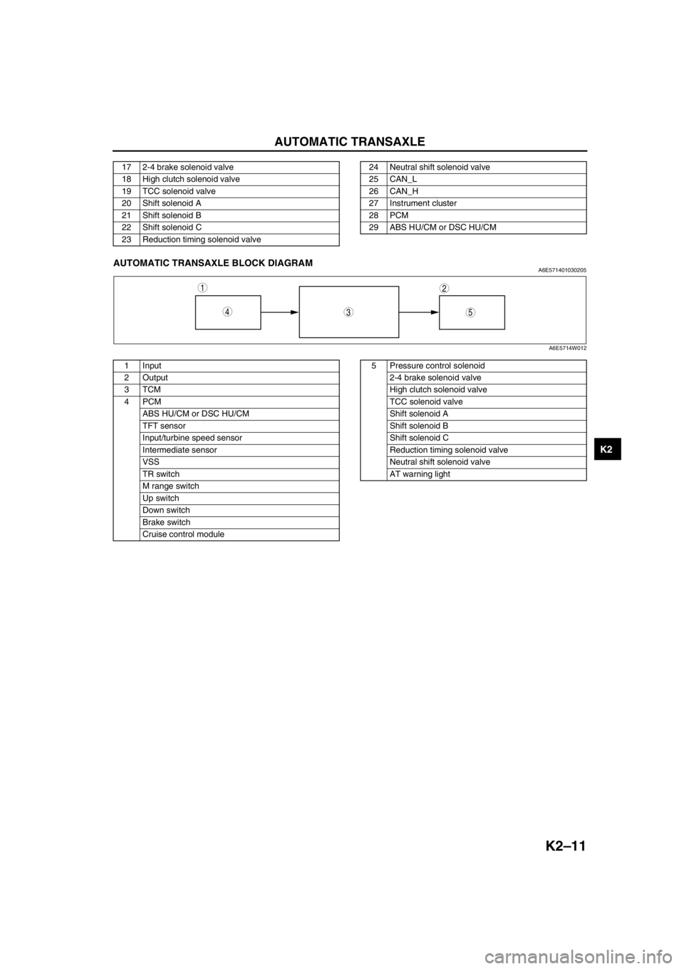
End Of SieAUTOMATIC TRANSAXLE BLOCK DIAGRAMA6E571401030205
.
17 2-4 brake solenoid valve
18 High clutch solenoid valve
19 TCC solenoid valve
20 Shift solenoid A
21 Shift solenoid B
22 Shift solenoid C
23 Reduction timing solenoid valve24 Neutral shift solenoid valve
25 CAN_L
26 CAN_H
27 Instrument cluster
28 PCM
29 ABS HU/CM or DSC HU/CM
543
12
A6E5714W012
1 Input
2Output
3TCM
4PCM
ABS HU/CM or DSC HU/CM
TFT sensor
Input/turbine speed sensor
Intermediate sensor
VSS
TR switch
M range switch
Up switch
Down switch
Brake switch
Cruise control module5 Pressure control solenoid
2-4 brake solenoid valve
High clutch solenoid valve
TCC solenoid valve
Shift solenoid A
Shift solenoid B
Shift solenoid C
Reduction timing solenoid valve
Neutral shift solenoid valve
AT warning light
Page 467 of 909
K2–52
AUTOMATIC TRANSAXLE
Operation
Range determination
•Each range is determined by operating the selector lever, and switching ON/OFF the switch in the TR switch
internal circuit. The present range is detected according to the ON/OFF signal of the switch.
•The following switches are built into the TR switch, and determine each range when the switch is on.
P position switch
R position switch
N position switch
D range switch
End Of Sie
MANUAL MODE SHIFT CONTROL DESCRIPTIONA6E571418901204Outline
Features
•The manual mode shift control is activated by moving the selector lever from the D to M range position (selector
lever is shifted over toward front passenger side).
•Manual mode shift control with a manual shifting system allowing selection of gear positions by manual
operation of the selector lever forward (-) and back (+) has been adopted. Moreover, engine braking for all
gears in manual mode according to the gear ratio is available.
— Shifting between 1GR and 2GR when the vehicle is stopped is possible.
— When shifting from the D to M range while driving, the same gear position is maintained.
— Consecutive shifting in the M range has been adopted. When shifting down from M range 4GR or 3GR, one
gear can be skipped over by rapidly tapping the selector lever two times in the down-shift (-) direction.
•Selector lever position and gear position indicator lights, built into the instrument cluster, have been adopted.
— The selector indicator light includes a selector lever position indicator that displays selector lever positions
and, a gear position indicator light that displays gear positions.
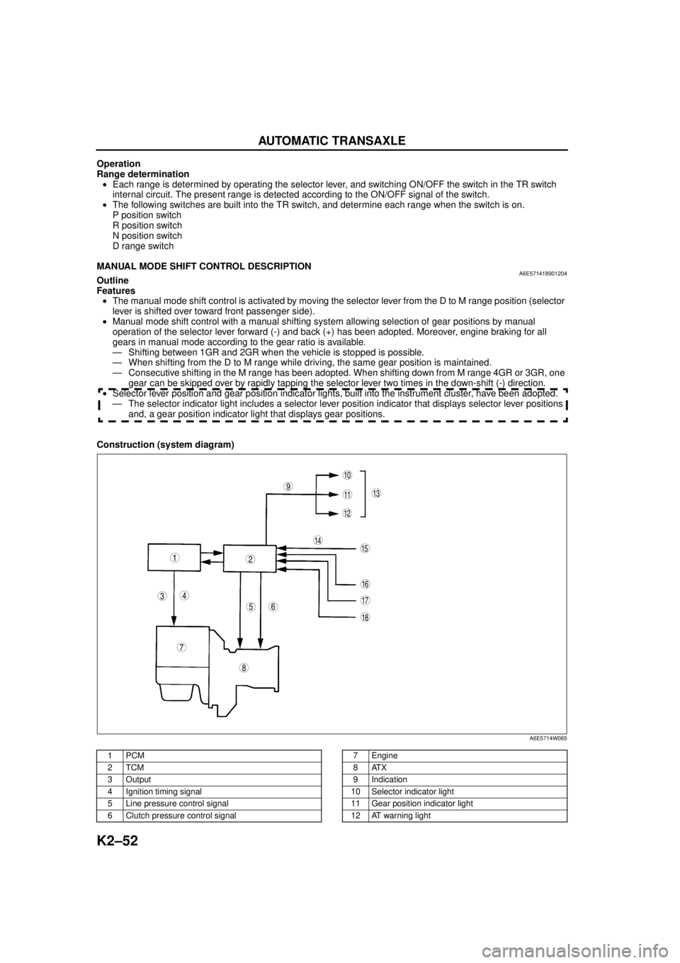
Construction (system diagram)
.
9
8
7
5
43
12
10
18
17
15
16
14
1311
12
6
A6E5714W065
1PCM
2TCM
3Output
4 Ignition timing signal
5 Line pressure control signal
6 Clutch pressure control signal7Engine
8ATX
9 Indication
10 Selector indicator light
11 Gear position indicator light
12 AT warning light
Page 468 of 909

AUTOMATIC TRANSAXLE
K2–53
K2
Operation
Manual mode shift
•When the selector lever is shifted over from the D to M range position, the M range switch in the selector lever
component turns on, sending a manual mode command signal to the PCM which activates the manual mode
shift control.
•When in manual mode and the selector lever is operated in the back (+) direction, the up switch in the selector
lever component is turned on and an up-shift command signal is inputted to the PCM.
—The PCM, triggered by the up-shift command signal, carries out shifting by outputting an operation signal to
the shift solenoid if the ATF temperature is not low (for 3GR only), vehicle speed is higher than the set
speed and the gear position is 3GR or lower.
•Conversely, when the selector lever is operated in the forward (-) direction, the down switch in the selector lever
component turns on, and a down-shift command signal is inputted to the PCM.
—The PCM, triggered by the down-shift command signal, carries out shifting by outputting an operation
signal to the shift solenoid if the vehicle speed is less than the set speed and the gear position is 2GR or
above.
•The PCM utilizes a specialized M range automatic shift diagram when down shifting. This restriction of manual
downshifting is carried out to reduce load on the ATX and prevent engine over-revving.
13 Instrument cluster
14 Input15 Selector lever component
-M range switch
-Up switch
-Down switch
16 TR switch
17 ABS HU/CM or DSC HU/CM
18 TFT sensor
Condition Shift control Note
2GR→3GR up-shift command
at low speed•To reduce load on the ATX, upshifting is
inhibited until vehicle reaches speed
possible for upshifting
— 3GR→4GR up-shift command
at low speed
3GR→4GR up-shift command,
low ATF temperature•To reduce load on the ATX, upshifting to
4GR is inhibited
4GR→3GR down-shift
command, above set speed•To prevent engine over-rev, downshifting is
inhibited until vehicle reaches speed
possible for downshifting•Selector indicator “M” light and gear
position indicator light flash to alert
driver
3GR→2GR down-shift
command, above set speed
2GR→1GR down-shift
command, above set speed
In 4GR deceleration, speed
goes below coast-down set
speed (deceleration down-
shift)•To assure drive stability, automatically
downshifts from 4GR to 3GR
— In 3GR deceleration, speed
goes below coast-down set
speed (deceleration down-
shift)•To assure drive stability, automatically
downshifts from 3GR to 1GR
In 2GR deceleration, speed
goes below coast-down set
speed (deceleration down-
shift)•To assure driving stability, automatically
downshifts from 2GR to 1GR
Page 479 of 909
K2–64
AUTOMATIC TRANSAXLE
ON-BOARD DIAGNOSTIC (OBD) SYSTEM DESCRIPTIONA6E571418901210•The OBD system has the following functions:
—Failure detection function: detects failure of the input/output devices and system components of the ATX.
—Memory function: stores the DTC when a failure is detected.
—Fail-safe function: fixes the output device function and input value of the sensors/switches to ensure
minimum vehicle drivability when a failure is detected.
—PID data monitoring function: monitors the input/output signal and calculated value of the TCM and sends
the monitoring data to the scan tool.
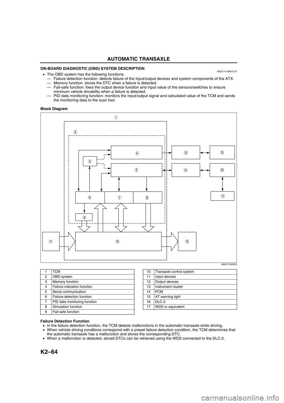
Block Diagram
.
Failure Detection Function
•In the failure detection function, the TCM detects malfunctions in the automatic transaxle while driving.
•When vehicle driving conditions correspond with a preset failure detection condition, the TCM determines that
the automatic transaxle has a malfunction and stores the corresponding DTC.
•When a malfunction is detected, stored DTCs can be retrieved using the WDS connected to the DLC-2.
9
87
5
4
3
1
2
10
17
15
1614
13
1112
6
A6E5714W023
1TCM
2 OBD system
3 Memory function
4 Failure indication function
5 Serial communication
6 Failure detection function
7 PID data monitoring function
8 Simulation function
9 Fail-safe function10 Transaxle control system
11 Input devices
12 Output devices
13 Instrument cluster
14 PCM
15 AT warning light
16 DLC-2
17 WDS or equivalent
Page 599 of 909
K2–184
TROUBLESHOOTING
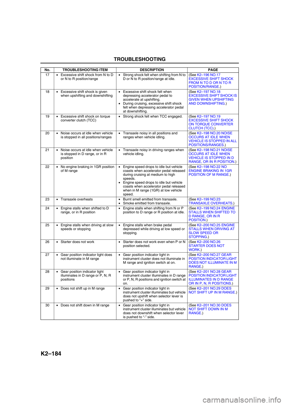
17•Excessive shift shock from N to D
or N to R position/range•Strong shock felt when shifting from N to
D or N to R position/range at idle.(See K2–196 NO.17
EXCESSIVE SHIFT SHOCK
FROM N TO D OR N TO R
POSITION/RANGE.)
18•Excessive shift shock is given
when upshifting and downshifting•Excessive shift shock felt when
depressing accelerator pedal to
accelerate at upshifting.
•During cruising, excessive shift shock
felt when depressing accelerator pedal
at downshifting.(See K2–197 NO.18
EXCESSIVE SHIFT SHOCK IS
GIVEN WHEN UPSHIFTING
AND DOWNSHIFTING.)
19•Excessive shift shock on torque
converter clutch (TCC)•Strong shock felt when TCC engaged. (See K2–197 NO.19
EXCESSIVE SHIFT SHOCK
ON TORQUE CONVERTER
CLUTCH (TCC).)
20•Noise occurs at idle when vehicle
is stopped in all positions/ranges•Transaxle noisy in all positions and
ranges when vehicle idling.(See K2–198 NO.20 NOISE
OCCURS AT IDLE WHEN
VEHICLE IS STOPPED IN ALL
POSITIONS/RANGES.)
21•Noise occurs at idle when vehicle
is stopped in D range, or in R
position•Transaxle noisy in driving ranges when
vehicle idling.(See K2–198 NO.21 NOISE
OCCURS AT IDLE WHEN
VEHICLE IS STOPPED IN D
RANGE, OR IN R POSITION.)
22•No engine braking in 1GR position
of M range•Engine speed drops to idle but vehicle
coasts when accelerator pedal released
during cruising at medium to high
speeds.
•Engine speed drops to idle but vehicle
coasts when accelerator pedal released
when in M range (1GR) at low vehicle
speed.(See K2–198 NO.22 NO
ENGINE BRAKING IN 1GR
POSITION OF M RANGE.)
23•Transaxle overheats•Burnt smell emitted from transaxle.
•Smoke emitted from transaxle.(See K2–199 NO.23
TRANSAXLE OVERHEATS.)
24•Engine stalls when shifted to D
range, or in R position•Engine stalls when shifting from N or P
position to D range or R position at idle.(See K2–199 NO.24 ENGINE
STALLS WHEN SHIFTED TO
D RANGE, OR IN R
POSITION.)
25•Engine stalls when driving at slow
speeds or stopping•Engine stalls when brake pedal
depressed while driving at low speed or
stopping.(See K2–200 NO.25 ENGINE
STALLS WHEN DRIVING AT
SLOW SPEED OR
STOPPING.)
26•Starter does not work•Starter does not work even when P or N
position selected.(See K2–200 NO.26
STARTER DOES NOT
WORK.)
27•Gear position indicator light does
not illuminate in M range•Gear position indicator light in
instrument cluster does not illuminate in
M range and ignition switch at on.(See K2–200 NO.27 GEAR
POSITION INDICATOR LIGHT
DOES NOT ILLUMINATE IN M
RANGE.)
28•Gear position indicator light
illuminates in D range or P, N, R
positions•Gear position indicator light in
instrument cluster illuminates in D range
or P, N, R positions and ignition switch at
on.(See K2–201 NO.28 GEAR
POSITION INDICATOR LIGHT
ILLUMINATES IN D RANGE
OR IN P, N, R POSITIONS.)
29•Does not shift up in M range•Gear position indicator light in
instrument cluster illuminates but vehicle
does not upshift when selector lever is
pushed to “+” side.(See K2–201 NO.29 DOES
NOT SHIFT UP IN M RANGE.)
30•Does not shift down in M range•Gear position indicator light in
instrument cluster illuminates but vehicle
does not downshift when selector lever
is pushed to “-” side.(See K2–201 NO.30 DOES
NOT SHIFT DOWN IN M
RANGE.) No. TROUBLESHOOTING ITEM DESCRIPTION PAGE
Page 615 of 909

K2–200
TROUBLESHOOTING
Diagnostic procedure
End Of SieNO.25 ENGINE STALLS WHEN DRIVING AT SLOW SPEED OR STOPPINGA6E578001030228
Diagnostic procedure
End Of SieNO.26 STARTER DOES NOT WORKA6E578001030229
End Of SieNO.27 GEAR POSITION INDICATOR LIGHT DOES NOT ILLUMINATE IN M RANGEA6E578001030230
Diagnostic procedure
STEP INSPECTION ACTION
1•Go to symptom troubleshooting No.4
“Engine stalls-after start/at idle”.
(See Section F.)
•Is engine control system okay?Yes Go to next step.
No Repair or replace any defective parts according to
inspection results.
2•Remove torque converter.
•Inspect torque converter.
(See ATX Workshop Manual.)
•Is torque converter okay?Yes•Inspect for bend, damage or kinks of oil cooler line
pipes. If okay, overhaul control valve body and repair or
replace any defective parts.
(See ATX Workshop Manual.)
•If problem remains, replace or overhaul transaxle and
repair or replace any defective parts.
(See ATX Workshop Manual.)
No Replace torque converter.
3•Verify test results.
—If okay, return to diagnostic index to service any additional symptoms.
—If malfunction remains, inspect related Service Informations and perform repair or diagnosis.
—If vehicle repaired, troubleshooting completed.
—If vehicle not repaired or additional diagnostic information not available, replace TCM.
25 Engine stalls when driving at slow speeds or stopping
DESCRIPTION•Engine stalls when brake pedal depressed while driving at low speed or stopping.
POSSIBLE
CAUSE•Malfunction is on engine control side (e.g. Fuel injection control, IAC system)
Note
•Before following troubleshooting steps, make sure that Automatic Transaxle On-Board Diagnostic
and Automatic Transaxle Basic Inspection are conducted.
STEP INSPECTION ACTION
1•Go to symptom troubleshooting No.10 “Low
idle/stalls during deceleration”.
(See Section F.)
•Is engine control system okay?Yes Go to symptom troubleshooting No.24 “Engine stalls when
shifted to D range, or in R position”.
No Repair or replace any defective parts according to
inspection results.
2•Verify test results.
—If okay, return to diagnostic index to service any additional symptoms.
—If malfunction remains, inspect related Service Informations and perform repair or diagnosis.
—If vehicle repaired, troubleshooting completed.
—If vehicle not repaired or additional diagnostic information not available, replace TCM.
26Starter does not work
DESCRIPTION•Starter does not work even when P or N position.
POSSIBLE
CAUSE•Selector lever misadjustment.
•TR switch misadjustment.
•Open or short circuit in TR switch.
27 Gear position indicator light does not illuminate in M range
DESCRIPTION•Gear position indicator light in instrument cluster does not illuminate in M range and ignition switch at
on.
POSSIBLE
CAUSE•M range switch, gear position indicator light or related wiring harness malfunction.
Note
•Before following troubleshooting steps, make sure that Automatic Transaxle On-Board Diagnostic
and Automatic Transaxle Basic Inspection are conducted.
STEP INSPECTION ACTION
1•Are other indicator lights illuminated with
ignition switch on? Yes Go to next step.
No Inspect meter fuse.
Page 616 of 909

TROUBLESHOOTING
K2–201
K2
End Of SieNO.28 GEAR POSITION INDICATOR LIGHT ILLUMINATES IN D RANGE OR IN P, N, R POSITIONSA6E578001030231
Diagnostic procedure
End Of SieNO.29 DOES NOT SHIFT UP IN M RANGEA6E578001030232
End Of SieNO.30 DOES NOT SHIFT DOWN IN M RANGEA6E578001030233
End Of Sie
2•Inspect MNL SW PID value using WDS or
equivalent.
•Are these PIDs okay?Yes Inspect instrument cluster.
No Inspect M range switch.
If M range switch is okay, inspect for continuity between M
range switch and TCM terminal 1AA.
3•Verify test results.
—If okay, return to diagnostic index to service any additional symptoms.
—If malfunction remains, inspect related Service Informations and perform repair or diagnosis.
—If vehicle repaired, troubleshooting completed.
—If vehicle not repaired or additional diagnostic information not available, replace TCM. STEP INSPECTION ACTION
28 Gear position indicator light illuminates when D range or P, N, R positions
DESCRIPTION•Gear position indicator light in instrument cluster illuminates in D range or P, N, R positions and ignition
switch at on.
POSSIBLE
CAUSE•M range switch or related wiring harness malfunction.
Note
•Before following troubleshooting steps, make sure that Automatic Transaxle On-Board Diagnostic
and Automatic Transaxle Basic Inspection are conducted.
STEP INSPECTION ACTION
1•Inspect MNL SW PID value using WDS or
equivalent.
•Are these PIDs okay?Yes Inspect instrument cluster.
No Inspect M range switch.
If M range switch is okay, inspect for continuity between M
range switch and TCM terminal 1AA.
2•Verify test results.
—If okay, return to diagnostic index to service any additional symptoms.
—If malfunction remains, inspect related Service Informations and perform repair or diagnosis.
—If vehicle repaired, troubleshooting completed.
—If vehicle not repaired or additional diagnostic information not available, replace TCM.
29Does not shift up in M range
DESCRIPTION•Gear position indicator light in instrument cluster illuminates, but vehicle does not upshift when selector
lever is pushed to “+” side.
POSSIBLE
CAUSE•Up switch or related harness malfunction
Note
•Before following troubleshooting steps, make sure that Automatic Transaxle On-Board
Diagnostic and Automatic Transaxle Basic Inspection are conducted.
30 Does not shift up in M range
DESCRIPTION•Gear position indicator light in instrument cluster illuminates, but vehicle does not downshift when
selector is pushed lever to “–” side.
POSSIBLE
CAUSE•Down switch or related harness malfunction
Note
•Before following troubleshooting steps, make sure that Automatic Transaxle On-Board
Diagnostic and Automatic Transaxle Basic Inspection are conducted.
Page 638 of 909
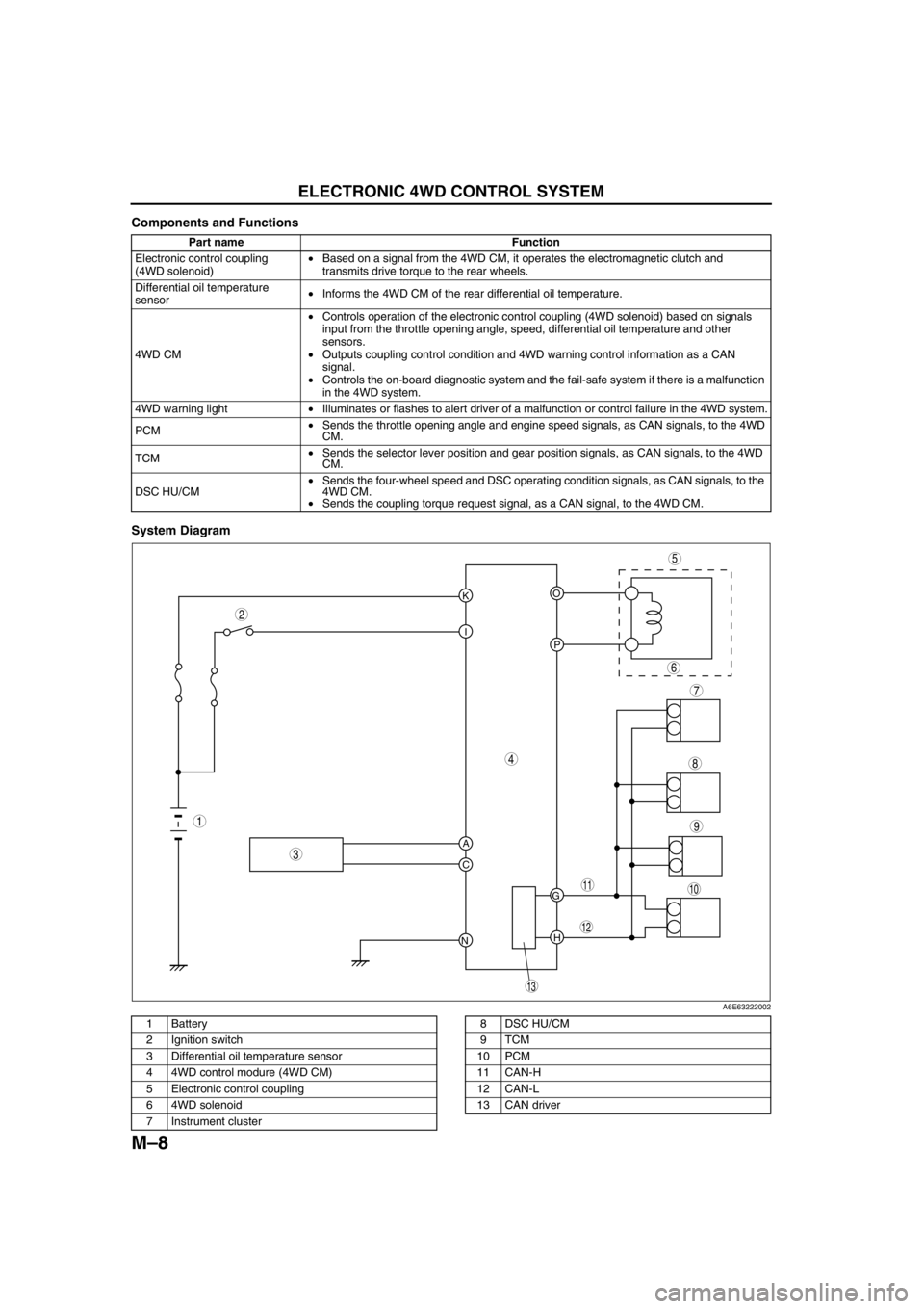
M–8
ELECTRONIC 4WD CONTROL SYSTEM
Components and Functions
System Diagram
.
Part name Function
Electronic control coupling
(4WD solenoid)•Based on a signal from the 4WD CM, it operates the electromagnetic clutch and
transmits drive torque to the rear wheels.
Differential oil temperature
sensor•Informs the 4WD CM of the rear differential oil temperature.
4WD CM•Controls operation of the electronic control coupling (4WD solenoid) based on signals
input from the throttle opening angle, speed, differential oil temperature and other
sensors.
•Outputs coupling control condition and 4WD warning control information as a CAN
signal.
•Controls the on-board diagnostic system and the fail-safe system if there is a malfunction
in the 4WD system.
4WD warning light•Illuminates or flashes to alert driver of a malfunction or control failure in the 4WD system.
PCM•Sends the throttle opening angle and engine speed signals, as CAN signals, to the 4WD
CM.
TCM•Sends the selector lever position and gear position signals, as CAN signals, to the 4WD
CM.
DSC HU/CM•Sends the four-wheel speed and DSC operating condition signals, as CAN signals, to the
4WD CM.
•Sends the coupling torque request signal, as a CAN signal, to the 4WD CM.
KO
P I
A
C
NH G
9
8
7
5
4
3
10
13
11
12
6
1
2
A6E63222002
1 Battery
2 Ignition switch
3 Differential oil temperature sensor
4 4WD control modure (4WD CM)
5 Electronic control coupling
6 4WD solenoid
7 Instrument cluster8 DSC HU/CM
9TCM
10 PCM
11 CAN-H
12 CAN-L
13 CAN driver