torque MAZDA 626 1987 Owners Manual
[x] Cancel search | Manufacturer: MAZDA, Model Year: 1987, Model line: 626, Model: MAZDA 626 1987Pages: 1865, PDF Size: 94.35 MB
Page 227 of 1865

ON-VEHICLE MAINTENANCE (TIMING BELT) 1 C
76G01C-027
76G01C-028
76G01C-029
Checking
point
Idler pulley
Crankshaft pulley zQi A/C
Checking point compressor
76G01C-030
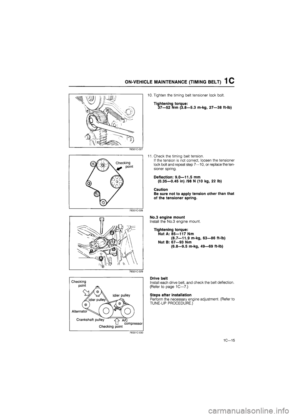
10. Tighten the timing belt tensioner lock bolt.
Tightening torque:
37—52
N
m (3.8—5.3 m-kg, 27—38 ft-lb)
11. Check the timing belt tension.
If the tension is not correct, loosen the tensioner
lock bolt and repeat step 7—10, or replace the ten-
sioner spring.
Deflection: 9.0—11.5 mm
(0.35—0.45 in) /98 N (10 kg, 22 lb)
Caution
Be sure not to apply tension other than that
of the tensioner spring.
No.3 engine mount
Install the No.3 engine mount.
Tightening torque:
Nut A: 85—117 N-m
(8.7—11.9 m-kg, 63—86 ft-lb)
Nut B: 67—93 N-m
(6.8—9.5 m-kg, 49—69 ft-lb)
Drive belt
Install each drive belt, and check the belt deflection.
(Refer to page 1C—7.)
Steps after installation
Perform the necessary engine adjustment. (Refer to
TUNE-UP PROCEDURE,)
1C-15
Page 231 of 1865

ON-VEHICLE MAINTENANCE (CYLINDER HEAD) 1 C
Installation
Install in the reverse order of removal referring to the installation note.
Note a) Position the hose clamp in the original location on the hose.
b) Squeeze the clamp lightly with large pliers to ensure a good fit.
Torque Specifications
59—69 N m (6.0—7.0 m-kg, 43—51 ft-lb)
55—65 N-m (5.6—6.6 m-kg, 41—48 ft-lb)
7-10 N-m (70—100 cm-kg, 61-87 in-lb)
8—11 N-m (80—110 cm-kg, 69—95 in-lb)
8—11 N-m (80—110 cm-kg. 69—95 In-lb)
55—65 N-m i—6.6 m-kg, 48 ft-lb)
—11 N-m (80—110 cm-kg, 69—95 in-lb)
7—10 N-m (70—100 cm-kg, 61—87 in-lb)
8—11 N-m (80—110 cm-kg, 69—95 in-lb)
34—49 N-m (3.5—!
\, - 16—27 N-m (1.6—2.8 m-kg, N > 12—20 ft-lb)
19—26 N-m (1.9—2.6 m-kg, 14—19 ft-lb)
76G01C-242
1C—19
Page 232 of 1865

ON-VEHICLE MAINTENANCE (CYLINDER HEAD) 1 C
76G01C-037
Apply engine oil
/
Cylinder head bolt
below head length
76G01C-038
(8) (4; D (5)
® ®
76G01C-039
3m-kg
(21.7ft-lb
Installation
Cylinder head
1. Throughly remove all dirt and grease from the top
of the cylinder block with a rag.
2. Place the new cylinder head gasket in position.
3. Remove any dirt and grease from the bottom sur-
face of the cylinder head.
4. Place the cylinder head in position.
5. Measure the length of the cylinder head bolt be-
low the head. If the length exceeds the maximum,
replace the bolt.
Length: 113.2—113.8 mm (4.457—4.480 in)
Maximum: 114.5 mm (4.508 in)
6. Apply engine oil to the threads and the seat face
of the cylinder head bolts.
7. Tighten the cylinder head bolts.
(1) Tighten the bolts to the specified torque, in the
order shown in the figure.
Tightening torque:
29 N-m (3.0 m-kg, 22 ft-lb)
(2) Make paint marks on the bolt heads, as shown
in the figure.
(3) With the paint marks as a reference point, turn
the cylinder head bolts another 90°
(90°—105°) in the tightening direction. Tight-
en them in the order.
(4) Then tighten them once again 90°
(90°—105°) in the tightening order.
Caution
Be absolutely sure that the bolts are tightened
in the proper order.
76G01C-044
1C—20
Page 233 of 1865

ON-VEHICLE MAINTENANCE (CYLINDER HEAD) 1 C
76G01C-041
76G01C-042
76G01C-043
Seal plate
1. Install the seal plate.
Tightening torque:
8—12
N
m (80—120 cm-kg, 69—104 in-lb)
2. Check that the seal plate sealing rubbers are in-
stalled in position.
Rear camshaft pulley
1. Install the rear camshaft pulley.
2. Hold the camshaft with a wrench (29 mm, 1.14 in),
and tighten to the specification.
Tightening torque:
55—65
N
m (5.6—6.6 m-kg, 41—48 ft-lb)
Camshaft pulley
1. Connect the camshaft pulley onto the camshaft with
the semicircular (woodruff) key.
2. Hold the camshaft with a wrench (29 mm, 1.14 in),
tighten the camshaft pulley lock bolt.
Tightening torque:
55—65 Nm (5.6—6.6 m-kg, 41—48 ft-lb)
3. Align the mark on the camshaft pulley with the mark
on the seal plate.
76G01C-044
1C—21
Page 234 of 1865

1 C ON-VEHICLE MAINTENANCE (CYLINDER HEAD)
76G01C-045
Gasket
Head cover Apply sealant
J
76G01C-046
76G01C-047
Timing marks
Timing marks
Timing
marks-
Injection pump pulley
1. Install the injection pump pulley with the semicir-
cular (woodruff) key to the injection pump shaft.
2. Rotate the injection pump pulley until the timing
marks are aligned.
3. Affix the injection pump pulley to the bracket us-
ing two bolts (35—40 mm, 1.4—1.6 in).
4. Tighten the lock nut.
Tightening torque:
59—69 Nm (6.0—7.0 m-kg, 43—51 ft-lb)
Cylinder head cover
1. Apply sealant to the shaded areas.
2. Install the cylinder head cover.
Tightening torque:
7—10
N
m (70—100 cm-kg, 61—87 in-lb)
3. Install the PCV hose.
Timing belt
1. Return the crankshaft about 45° to the timing mark
on the oil pump housing.
2. Check that the timing marks of the camshaft pul-
ley and the injection pump pulley align with the tim-
ing marks on the seal plate.
3. Install the timing belt. (Refer to TIMING BELT of
ON-VEHICLE MAINTENANCE)
76G01C-048
1C-22
Page 235 of 1865

ON-VEHICLE MAINTENANCE (CYLINDER HEAD) 1 C
76G01C-049
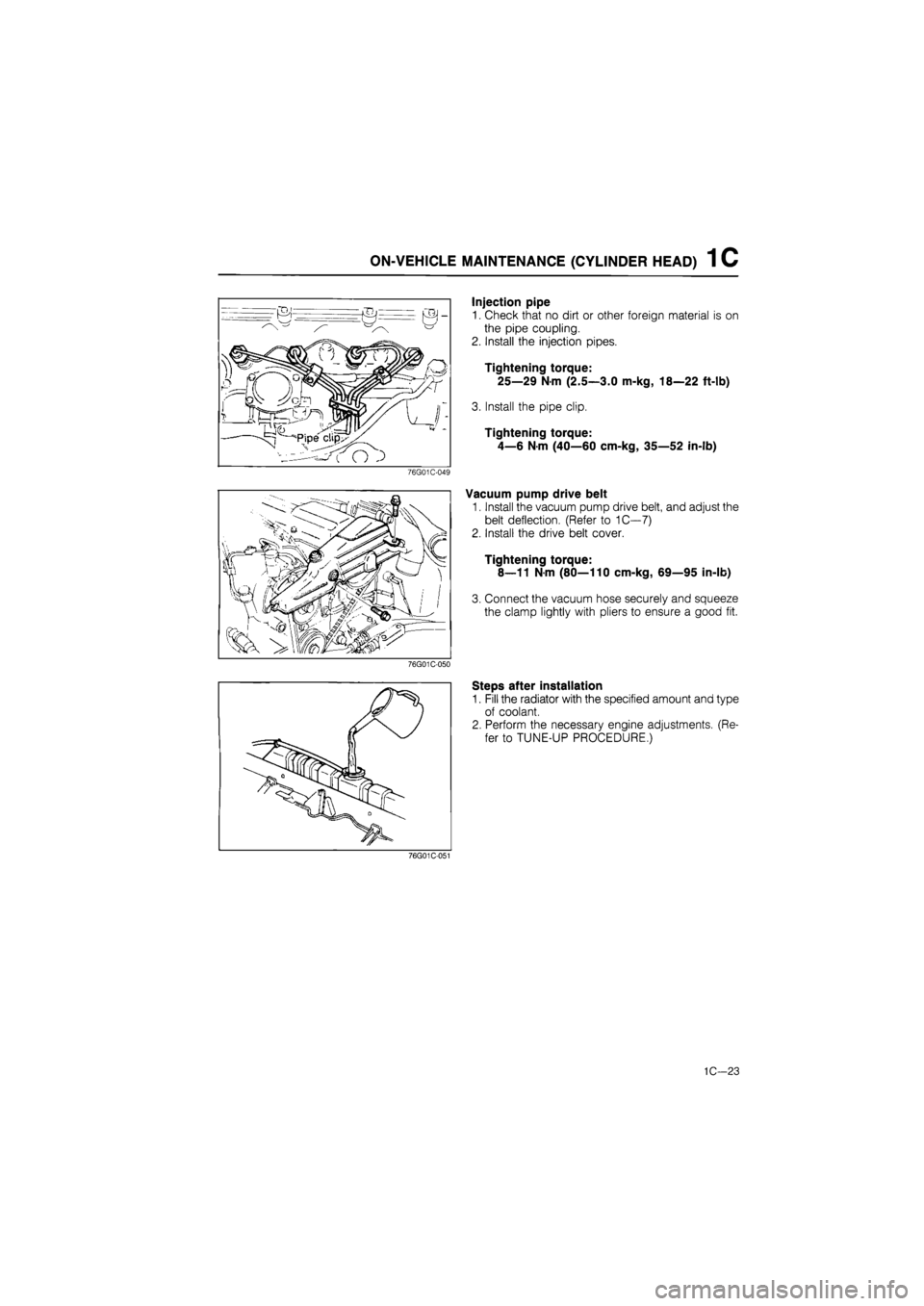
Injection pipe
1. Check that no dirt or other foreign material is on
the pipe coupling.
2. Install the injection pipes.
Tightening torque:
25—29 Nm (2.5—3.0 m-kg, 18—22 ft-lb)
3. Install the pipe clip.
Tightening torque:
4—6 N-m (40—60 cm-kg, 35—52 in-lb)
Vacuum pump drive belt
1. Install the vacuum pump drive belt, and adjust the
belt deflection. (Refer to 1C—7)
2. Install the drive belt cover.
Tightening torque:
8—11 Nm (80—110 cm-kg, 69—95 in-lb)
3. Connect the vacuum hose securely and squeeze
the clamp lightly with pliers to ensure a good fit.
76G01C-050
Steps after installation
1. Fill the radiator with the specified amount and type
of coolant.
2. Perform the necessary engine adjustments. (Re-
fer to TUNE-UP PROCEDURE.)
76G01C-051
1C—23
Page 239 of 1865

ON-VEHICLE MAINTENANCE (VALVE SEAL) 1 C
Installation
Install in the reverse order of removal referring to the installation note.
Torque Specifications
20—26 N-m (2.0—2.7 m-kg, 14—20 ft-lb)
N-m (5.6—6.6 m-kg, ft-lb)
55—65 N m (5.6—6.6 m-kg, 41—48 ft-lb)
76G01C-243
Installation note
Valve seal
1. Apply engine oil to the inside of the new valve seal.
2. Push it on gently with the SST.
86U01X-049
1C—27
Page 241 of 1865

ON-VEHICLE MAINTENANCE (VALVE SEAL) 1 C
4. Set the camshaft and camshaft cap so that the key
groove faces directly upward.
And tighten the cap nuts loosely.
5. Apply a coat of engine oil to the new oil seal lip
and insert it.
76G01C-063
6. Tighten the camshaft cap nuts gradually and in the
order shown in the figure.
Tightening torque:
20—26 N-m (2.0—2.7 m-kg, 14—20 ft-lb)
76G01C-064
Camshaft pulley and rear camshaft pulley
Hold the camshaft with a wrench (29 mm, 1.14 in),
tighten the camshaft pulley and rear camshaft pul-
ley lock bolts.
Tightening torque:
55—65 N-m (5.6—6.6 m-kg, 41—48 ft-lb)
76G01C-066
1C—29
Page 242 of 1865

1 C ON-VEHICLE MAINTENANCE (VALVE SEAL)
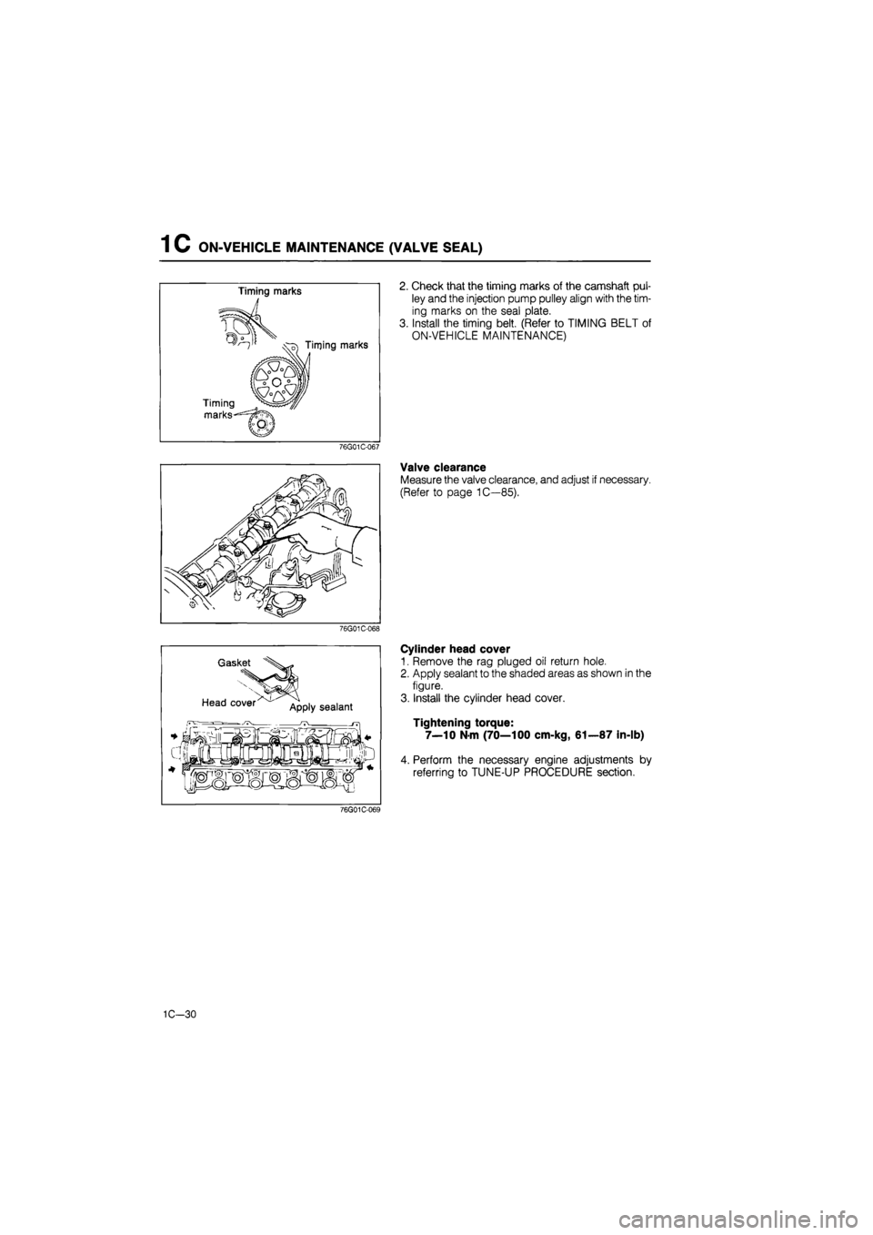
2. Check that the timing marks of the camshaft pul-
ley and the injection pump pulley align with the tim-
ing marks on the seal plate.
3. Install the timing belt. (Refer to TIMING BELT of
ON-VEHICLE MAINTENANCE)
76G01C-067
Valve clearance
Measure the valve clearance, and adjust if necessary.
(Refer to page 1C—85).
76G01C-068
Gasket
Head cover App|y sealant
Cylinder head cover
1. Remove the rag pluged oil return hole.
2. Apply sealant to the shaded areas as shown in the
figure.
3. Install the cylinder head cover.
Tightening torque:
7—10 Nm (70—100 cm-kg, 61—87 in-lb)
4. Perform the necessary engine adjustments by
referring to TUNE-UP PROCEDURE section.
76G01C-069
1C-30
Page 258 of 1865

1 C DISASSEMBLY (CYLINDER BLOCK)
Piston and connecting rod
1. Before disassembling the piston and connecting
rod, check the oscillation torque as shown in the
figure. If the large end does not drop by its own
weight, replace the piston or the piston pin.
76G01C-095
2. Remove the snap rings from the piston.
3. Remove the piston pin with the SST.
76G01C-249
76G01C-096
Main bearing cap
During disassembly, clean the bearings, main jour-
nals, and caps, and measure the following:
1. Crankshaft end play. (Refer to page 1C—65.)
2. Main journal oil clearance. (Refer to page 1C—64.)
Pilot bearing
Remove the pilot bearing from the crankshaft with the
SST.
76G01C-097
1C—46