lights MAZDA 626 1987 Workshop Manual
[x] Cancel search | Manufacturer: MAZDA, Model Year: 1987, Model line: 626, Model: MAZDA 626 1987Pages: 1865, PDF Size: 94.35 MB
Page 14 of 1865
0 PRE-DELIVERY INSPECTION
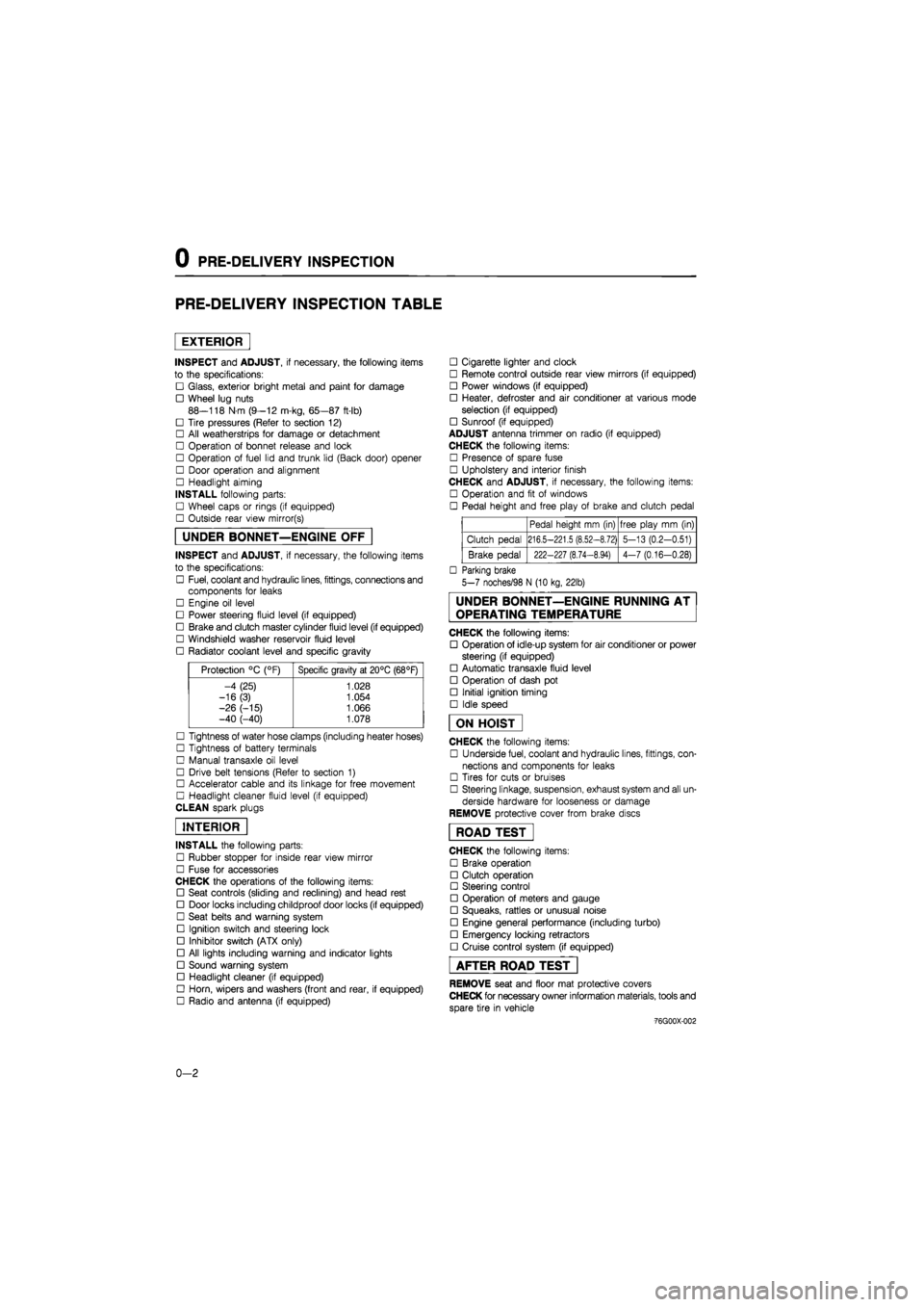
PRE-DELIVERY INSPECTION TABLE
EXTERIOR
INSPECT and ADJUST, if necessary, the following items
to the specifications:
• Glass, exterior bright metal and paint for damage
• Wheel lug nuts
88—118 N m (9—12 m-kg, 65—87 ft-lb)
• Tire pressures (Refer to section 12)
• All weatherstrips for damage or detachment
• Operation of bonnet release and lock
• Operation of fuel lid and trunk lid (Back door) opener
• Door operation and alignment
• Headlight aiming
INSTALL following parts:
• Wheel caps or rings (if equipped)
• Outside rear view mirror(s)
UNDER BONNET—ENGINE OFF
INSPECT and ADJUST, if necessary, the following items
to the specifications:
• Fuel, coolant and hydraulic lines, fittings, connections and
components for leaks
• Engine oil level
• Power steering fluid level (if equipped)
• Brake and clutch master cylinder fluid level (if equipped)
• Windshield washer reservoir fluid level
• Radiator coolant level and specific gravity
Protection °C (°F) Specific gravity at 20°C (68°F)
-4 (25) 1.028
-16(3) 1.054
-26 (-15) 1.066 -40 (-40) 1.078
• Tightness of water hose clamps (including heater hoses)
• Tightness of battery terminals
• Manual transaxle oil level
• Drive belt tensions (Refer to section 1)
• Accelerator cable and its linkage for free movement
• Headlight cleaner fluid level (if equipped)
CLEAN spark plugs
INTERIOR
INSTALL the following parts:
• Rubber stopper for inside rear view mirror
• Fuse for accessories
CHECK the operations of the following items:
• Seat controls (sliding and reclining) and head rest
• Door locks including childproof door locks (if equipped)
• Seat belts and warning system
• Ignition switch and steering lock
• Inhibitor switch (ATX only)
• All lights including warning and indicator lights
• Sound warning system
• Headlight cleaner (if equipped)
• Horn, wipers and washers (front and rear, if equipped)
• Radio and antenna (if equipped)
• Cigarette lighter and clock
• Remote control outside rear view mirrors (if equipped)
• Power windows (if equipped)
• Heater, defroster and air conditioner at various mode
selection (if equipped)
• Sunroof (if equipped)
ADJUST antenna trimmer on radio (if equipped)
CHECK the following items:
• Presence of spare fuse
• Upholstery and interior finish
CHECK and ADJUST, if necessary, the following items:
• Operation and fit of windows
• Pedal height and free play of brake and clutch pedal
Pedal height mm (in) free play mm (in)
Clutch pedal 216.5-221.5 (8.52-8.72) 5-13 (0.2-0.51)
Brake pedal 222-227 (8.74-8.94) 4-7 (0.16-0.28)
• Parking brake
5-7 noches/98 N (10 kg, 22lb)
UNDER BONNET—ENGINE RUNNING AT
OPERATING TEMPERATURE
CHECK the following items:
• Operation of idle-up system for air conditioner or power
steering (if equipped)
• Automatic transaxle fluid level
• Operation of dash pot
• Initial ignition timing
• Idle speed
ON HOIST
CHECK the following items:
• Underside fuel, coolant and hydraulic lines, fittings, con-
nections and components for leaks
• Tires for cuts or bruises
• Steering linkage, suspension, exhaust system and all un-
derside hardware for looseness or damage
REMOVE protective cover from brake discs
ROAD TEST"
CHECK the following items:
• Brake operation
• Clutch operation
• Steering control
• Operation of meters and gauge
• Squeaks, rattles or unusual noise
• Engine general performance (including turbo)
• Emergency locking retractors
• Cruise control system (if equipped)
AFTER ROAD TEST
REMOVE seat and floor mat protective covers
CHECK for necessary owner information materials, tools and
spare tire in vehicle
-76G00X-002
0-2
Page 15 of 1865
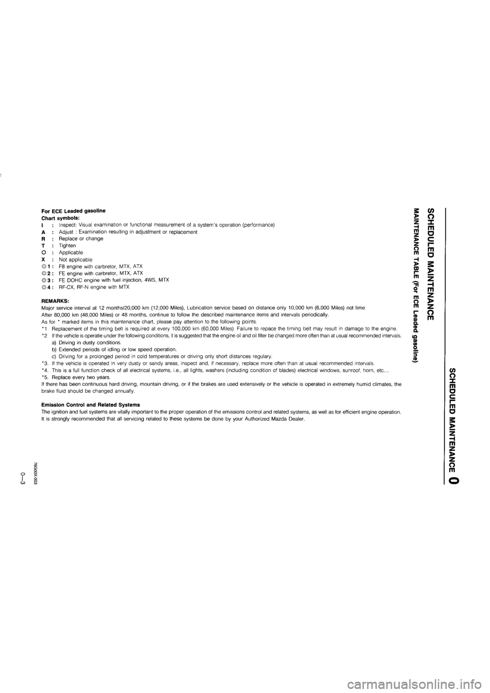
For ECE Leaded gasoline
Chart symbols:
I
A
R
T
O
X
Inspect: Visual examination or functional measurement of a system's operation (performance)
Adjust : Examination resulting in adjustment or replacement
Replace or change
Tighten
Applicable
Not applicable
F8 engine with carbretor, MTX, ATX
FE engine with carbretor, MTX, ATX
FE DOHC engine with fuel injection, 4WS, MTX
RF-CX, RF-N engine with MTX
REMARKS:
Major service interval at 12 months/20,000 km (12,000 Miles), Lubrication service based on distance only 10,000 km (6,000 Miles) not time
After 80,000 km (48,000 Miles) or 48 months, continue to follow the described maintenance items and intervals periodically.
As for * marked items in this maintenance chart, please pay attention to the following points.
*1 Replacement of the timing belt is required at every 100,000 km (60,000 Miles). Failure to repace the timing belt may result in damage to the engine.
*2 If the vehicle is operatie under the following conditions, it is suggested that the engine oil and oil filter be changed more often than at usual recommended intervals.
a) Driving in dusty conditions.
b) Extended periods of idling or low speed operation.
c) Driving for a prolonged period in cold temperatures or driving only short distances regulary.
*3. If the vehicle is operated in very dusty or sandy areas, inspect and, if necessary, replace more often than at usual recommended intervals.
*4. This is a full function check of all electrical systems, i.e., all lights, washers (including condition of blades) electrical windows, sunroof, horn, etc....
*5. Replace every two years.
If there has been continuous hard driving, mountain driving, or if the brakes are used extensively or the vehicle is operated in extremely humid climates, the
brake fluid should be changed annually.
>
Z H m >
o m
H >
CD r-m
o m
m O m
(D o> Q. ® a
(Q 0) <0 o
m a
o m
c/> o x m a
Emission Control and Related Systems
The ignition and fuel systems are vitally important to the proper operation of the emissions control and related systems, as well as for efficient engine operation.
It is strongly recommended that all servicing related to these systems be done by your Authorized Mazda Dealer.
m a
m z >
z o m
G)
Page 21 of 1865
r
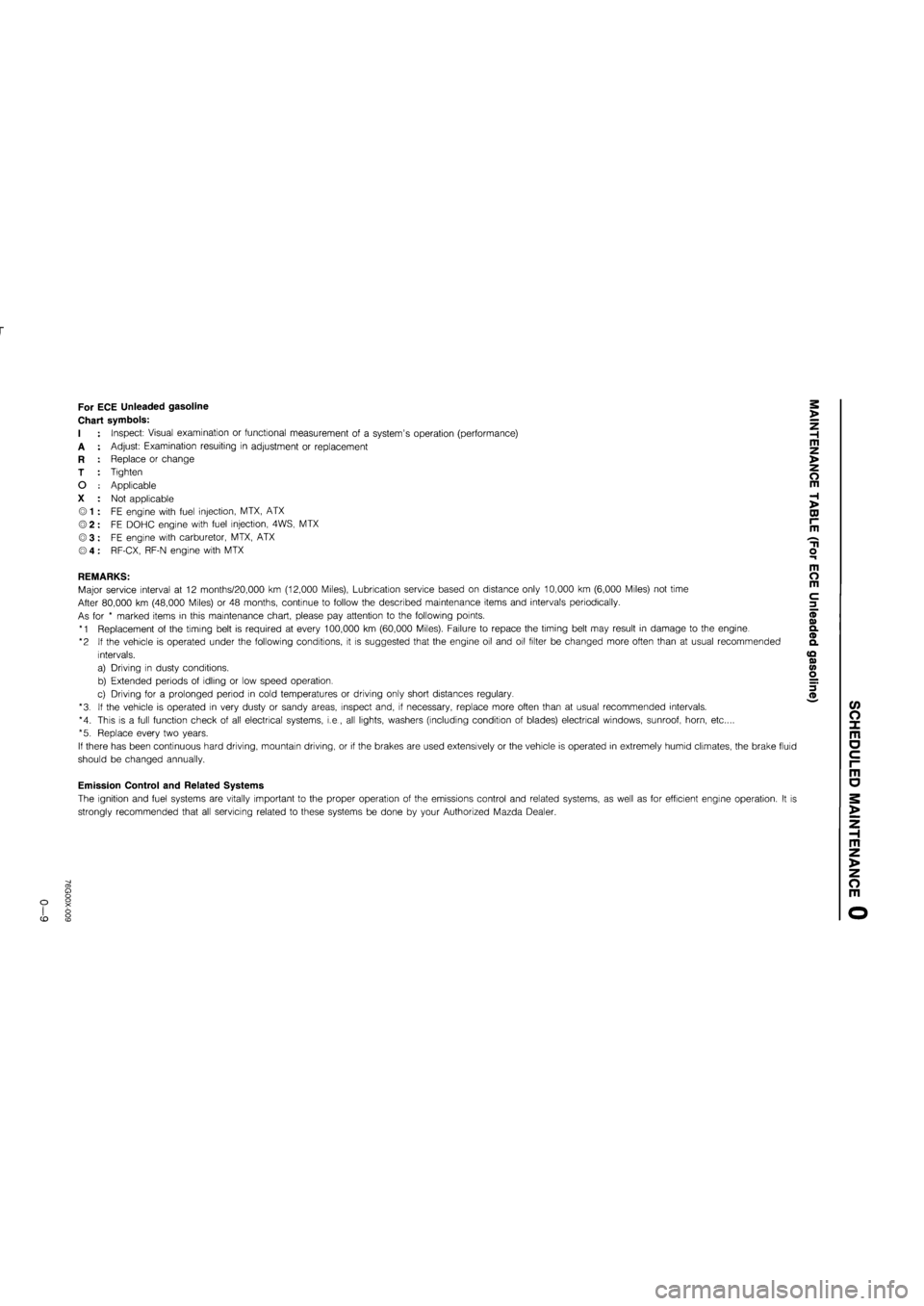
For ECE Unleaded gasoline
Chart symbols:
I
A
R
T
O
X
Inspect: Visual examination or functional measurement of a system's operation (performance)
Adjust: Examination resulting in adjustment or replacement
Replace or change
Tighten
Applicable
Not applicable
FE engine with fuel injection, MTX, ATX
FE DOHC engine with fuel injection, 4WS, MTX
FE engine with carburetor, MTX, ATX
RF-CX, RF-N engine with MTX
REMARKS:
Major service interval at 12 months/20,000 km (12,000 Miles), Lubrication service based on distance only 10,000 km (6,000 Miles) not time
After 80,000 km (48,000 Miles) or 48 months, continue to follow the described maintenance items and intervals periodically.
As for * marked items in this maintenance chart, please pay attention to the following points.
*1 Replacement of the timing belt is required at every 100,000 km (60,000 Miles). Failure to repace the timing belt may result in damage to the engine.
*2 If the vehicle is operated under the following conditions, it is suggested that the engine oil and oil filter be changed more often than at usual recommended
intervals.
a) Driving in dusty conditions.
b) Extended periods of idling or low speed operation.
c) Driving for a prolonged period in cold temperatures or driving only short distances regulary.
*3. If the vehicle is operated in very dusty or sandy areas, inspect and, if necessary, replace more often than at usual recommended intervals.
*4. This is a full function check of all electrical systems, i.e., all lights, washers (including condition of blades) electrical windows, sunroof, horn, etc....
*5. Replace every two years.
If there has been continuous hard driving, mountain driving, or if the brakes are used extensively or the vehicle is operated in extremely humid climates, the brake fluid
should be changed annually.
Emission Control and Related Systems
The ignition and fuel systems are vitally important to the proper operation of the emissions control and related systems, as well as for efficient engine operation. It is
strongly recommended that all servicing related to these systems be done by your Authorized Mazda Dealer.
>
Z H m z >
o m
H >
DJ r~ m
m o m
c 3
(/> O X m o c i-m
o
m z >
z o m
CD
Page 441 of 1865

4A IDLE-UP CONTROL SYSTEM
IDLE-UP SOLENOID VALVE
FE and F8 (General, ECE, Hong Kong, and Singapore)
Water thermo switch Fan speed control switch Headlights _
Rear defroster
A/C
Engine1
control -
unit
Richer air bleed
Richer jet
/ '
Inhibitor switch
Water thermo switch Fan speed _ control switch Headlights -
Rear defroster —
A/C
Engine
control
unit
Idle-up solenoid valve
Adjust screw
Secondary
throttle valve
From secondary main jet
76G04A-151
The idle-up solenoid valve opens when the following conditions are met.
Condition
When inhibitor switch is OFF (ATX—other than "P" and "N" range) and any of the following:
• Engine coolant temperature less than 72°C (162°F).
• A/C operated.
• Fan speed control switch 3rd or 4th position.
• Headlights turned on.
• Rear defroster turned on.
4A—76
Page 458 of 1865

CONTROL SYSTEM 4 A
76G04A-176
76G04A-177
76G04A-178
Replacement
1. Disconnect the negative battery cable.
2. Remove the front console covers (right or left).
3. Disconnect the connectors from the control unit.
4. Remove and replace the control unit.
INHIBITOR SWITCH
Inspection
1. Verify that the starter operates with the ignition
switch at START position in
P
and N positions only.
2. Check that the back-up lights illuminate when R
position selected and the ignition switch is ON.
3. If not as specified, check the following:
(1) Jack up the vehicle and support it with safety
stands.
(2) Disconnect the inhibitor switch connector.
(3) Check continuity of the switch with an
ohmmeter.
Connecting guide
Position
N
D,1,2
Connector terminal
O -O
O
O
-O
-O
O—O: indicates continuity
4. Replace if necessary.
IDLE SWITCH
Inspection
1. Warm up the engine and run it at idle.
2. Turn all accessories OFF.
3. Connect a tachometer to the engine.
4. Connect a voltmeter to the carburetor connector
F terminal.
76G04A-179
4A-93
Page 550 of 1865

4B CONTROL SYSTEM
Terminal Voltage
If the input and output devices and related wiring are normal, but the engine control unit terminal volt-
age is incorrect, replace the engine control unit.
Terminal Input Output Connection to Voltage (After warming-up) Remarks Terminal Input Output Connection to IGN: ON Idle Remarks
1A — — — — —
1B o Self-Diagnosis Checker (Code number)
For 3sec. after ignition switch OFF ->• ON: below 6.2V (Buzzer sounds) After 3sec.: Battery voltage (Buzzer does not sound)
• Using Self-Diagnosis Check-er and test con-nector grounded • Buzzer sounds: below 6.2V • Buzzer does not sound: Battery voltage
1C — — — — —
1D o Self-Diagnosis Checker (Monitor lamp)
Test connector grounded
For 3sec. after igni-tion switch OFF ON:
below 6.2V (light il-luminates) After 3sec.: Battery voltage (light does not illuminate)
(Test connector grounded) approx. 10V (Test connector not grounded) Monitor lamp ON: below 6.2V Monitor lamp OFF: Battery voltage
With Self-Diagnosis
Checker
1E O Idle switch Accelerator pedal released: below 1.5V
Accelerator pedal depressed: Battery voltage
1F o A/C relay A/C switch ON: below 2.5V A/C switch OFF: Battery voltage
Blower motor ON
1G — — — — —
1H o Water thermo switch Below 1,5V Radiator temp.:
above 17°C (63°F)
11 o Electrical load con-trol unit Electrical load ON: below 1.5V Electrical load OFF: Battery voltage Electrical load: Rear defroster Headlight Blower motor (3rd & 4th position) Electrical fan
1J o Brake light switch Brake pedal released: below 1.5V
Brake pedal depressed: battery voltage
1K — — — — — —
1L o A/C switch A/C switch ON: below 1.5V
A/C switch OFF: battery voltage
Blower motor: ON
1M o Ignition coil © terminal Battery voltage *1 Battery voltage *1 Engine Signal Monitor: green and red lights flash
1N — — — — —
10 — — — —
4B-88
Page 552 of 1865

4B CONTROL SYSTEM
Terminal Input Output Connection to Voltage (After warming-up) Remarks Terminal Input Output Connection to IGN: ON Idle Remarks
2N o Solenoid valve (EGR) Below 1,5V • Cold engine: be-low 1,5V Radiator coolant temp.—below 17°C (63°F) or Engine coolant temp.—below 70°C (158°F)
• Engine above ap-prox. 1,500 rpm: Battery voltage
20 o Air bypass solenoid valve (Idle-up B) Battery voltage While solenoid ON (Refer to page 4B-35): below 1.5 V
2P o Solenoid valve
(Purge control valve)
Battery voltage • Medium and high
load: below 1,5V
2Q — — — —
2R — — Ground (E02) Below 1,5V
3A — — Ground (E01) Below 1.5V
3B O Ignition switch (Start position) Below 1,5V While cranking: bat-
tery voltage
3C o Injector (No. 4 and No. 2) Battery voltage *1 Battery voltage *1 Engine Signal Monitor green and red lights flash
3D o Inhibitor switch "N" or "P" range: below 2.0V
Other ranges: battery voltage
ATX
3E o Injector (No. 1 and No. 3) Battery voltage *
1
Battery voltage *1 Engine Signal Monitor: green and red lights flash
3F -— — — —
3G — Ground (Ei) Below 1.5V
3H — — — —
31 o — Ma ri relay Battery voltage
3J — — Battery Battery voltage For back-up
76G04B-110
31 3G 3E 3C 3A
3J 3H 3F 3D 3B
2Q 20 2M 2K 21 2G 2E 2C 2A
2R 2P 2N 2L 2J 2H 2F 2D 2B
1W 1U 1S 1Q 10 1M 1K 11 1G 1E 1C 1A
1X 1V 1T 1R 1P 1N 1L 1J 1H 1F 1D 1B
4B—90
Page 661 of 1865
4C CONTROL SYSTEM
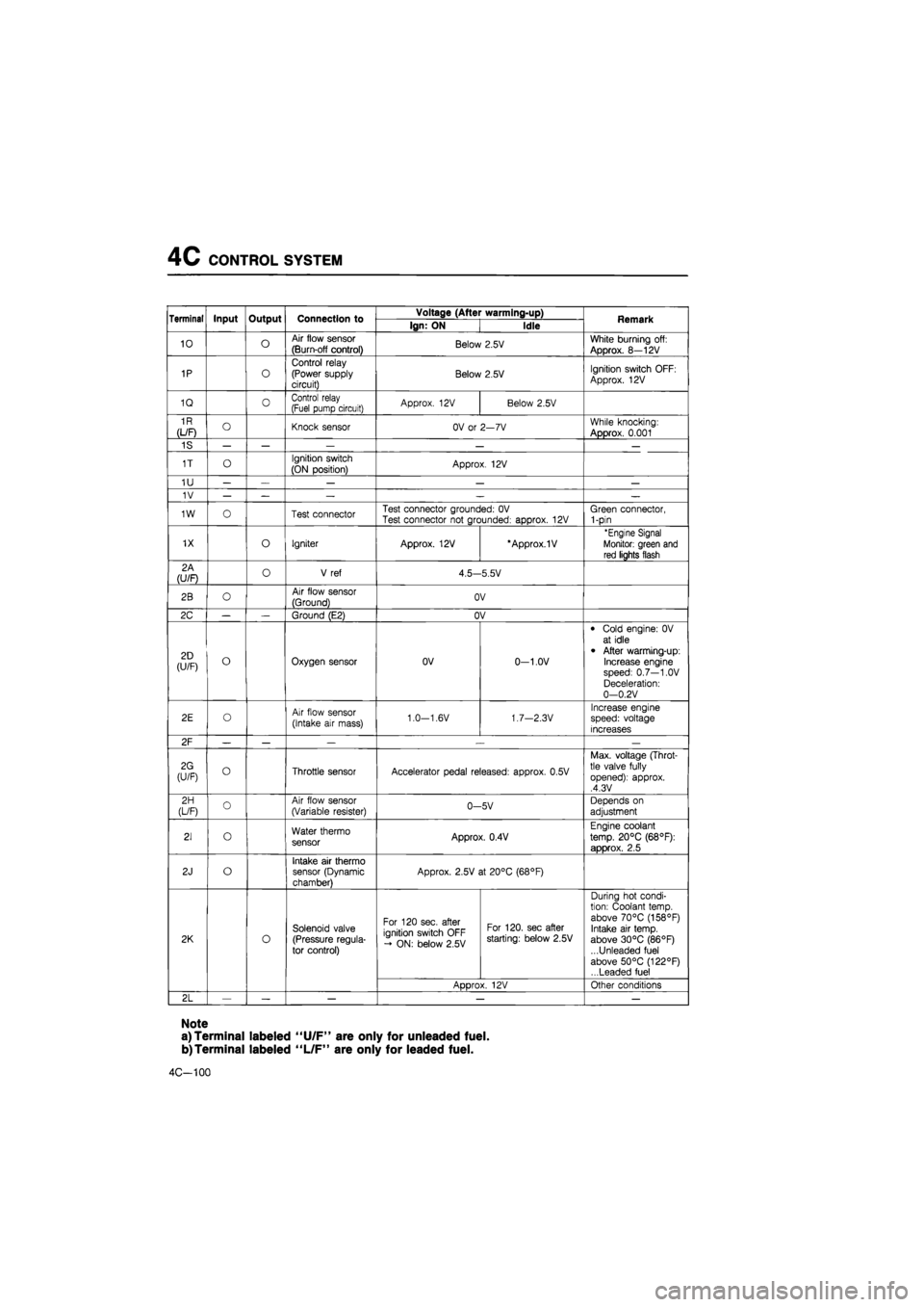
Terminal Input Output Connection to Voltage (After warming-up) Remark Terminal Input Output Connection to Ign: ON Idle Remark
10 o Air flow sensor
(Burn-off control) Below 2.5V White burning off:
Approx. 8—12V
1P o
Control relay (Power supply circuit) Below 2.5V Ignition switch OFF:
Approx. 12V
1Q 0 Control relay (Fuel pump circuit) Approx. 12V Below 2.5V
1R
(L/F) O Knock sensor OV or 2—7V While knocking:
Approx. 0.001
1S — — — — —
1T o Ignition switch
(ON position) Approx. 12V
1U — — — — —
1V — — — — —
1W o Test connector Test connector grounded: OV Test connector not grounded: approx. 12V Green connector, 1-pin
1X o Igniter Approx. 12V *Approx.1V 'Engine Signal
Monitor: green and
red lights flash
2A (U/F) o V ref 4.5—5.5V
2B o Air flow sensor
(Ground) OV
2C — — Ground (E2) OV
2D (U/F) o Oxygen sensor OV 0-1.0V
• Cold engine: 0V at idle
• After warming-up: Increase engine speed: 0.7—1.0V Deceleration: 0—0.2V
2E o Air flow sensor
(Intake air mass) 1.0—1.6V 1.7—2.3V Increase engine speed: voltage increases
2F — — — .— —
2G (U/F) o Throttle sensor Accelerator pedal released: approx. 0.5V
Max. voltage (Throt-tle valve fully opened): approx. ,4.3V
2H (L/F) o Air flow sensor (Variable resister) 0-5V Depends on
adjustment
21 o Water thermo sensor Approx. 0.4V
Engine coolant
temp. 20°C (68°F):
approx. 2.5
2J o Intake air thermo sensor (Dynamic chamber)
Approx. 2.5V at 20°C (68°F)
2K o
Solenoid valve (Pressure regula-tor control)
For 120 sec. after ignition switch OFF - ON: below 2.5V
For 120. sec after starting: below 2.5V
During hot condi-tion: Coolant temp, above 70°C (158°F) Intake air temp, above 30°C (86°F) ...Unleaded fuel above 50°C (122°F) ...Leaded fuel
2K o
Solenoid valve (Pressure regula-tor control)
ADDrox. 12V Other conditions
2L — — — — —
Note
a) Terminal labeled "U/F" are only for unleaded fuel.
b)Terminal labeled "L/F" are only for leaded fuel.
4C-100
Page 662 of 1865
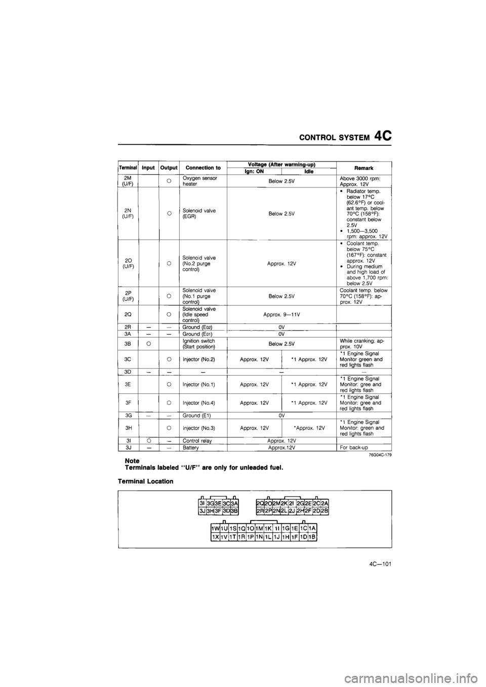
CONTROL SYSTEM 4C
Terminal Input Output Connection to Voltage (After warming-up) Remark Terminal Input Output Connection to Ign: ON Idle Remark
2M
(U/F) o Oxygen sensor
heater Below 2.5V Above 3000 rpm: Approx. 12V
2N
(U/F) o Solenoid valve (EGR) Below 2.5V
• Radiator temp, below 17°C (62.6°F) or cool-ant temp, below 70°C (158°F): constant below 2.5 V
• 1,500-3,500 rpm: approx. 12V
20 (U/F) 0 Solenoid valve (No.2 purge control) Approx. 12V
• Coolant temp, below 75 °C (167°F): constant approx. 12V
• During medium and high load of above 1,700 rpm: below 2.5V
2P
(U/F) o
Solenoid valve
(No.1 purge
control)
Below 2.5V
Coolant temp, below 70°C (158°F): ap-prox. 12V
2Q o Solenoid valve (Idle speed control) Approx. 9—11V
2R — — Ground (E02) OV
3A — — Ground (E01) OV
3B O Ignition switch
(Start position) Below 2.5V While cranking: ap-
Drox. 10V
3C o Injector (No.2) Approx. 12V *1 Approx. 12V
*1 Engine Signal Monitor green and red liahts flash
3D — — — — —
3E o Injector (No.1) Approx. 12V *1 Approx. 12V
*1 Engine Signal
Monitor: gree and
red liahts flash
3F 0 Injector (No.4) Approx. 12V *1 Approx. 12V
*1 Engine Signal Monitor: gree and red liahts flash
3G — Ground (E1) OV
3H o Injector (No.3) Approx. 12V 'Approx. 12V *1 Engine Signal
Monitor: green and
red lights flash
31 0 — Control relav ADDrox. 12V
3J — — Battery Approx. 12V For back-uD
76G04C-179
Note
Terminals labeled "U/F" are only for unleaded fuel.
Terminal Location
31 3G 3E 3C 3A
3J 3H 3F 3D 3B
2Q 2d 2M *
L
2G 2E 2C <
CM
2R 2P 2N 2L 2J 2H 2F 20 2B
1W 1U 1S 1Q 10 1M 1K 11 1G 1E 1C 1A
1X 1V 1T 1R 1P 1N 1L 1J 1H 1F 1D 1B
4C-101
Page 731 of 1865

ALTERNATOR 5
Warning
Disconnect the nagative battery terminal when disconnect or reconnect B terminal.
TEST 1
1. Disconnect the alternator connector (2-pin).
2. Connect the SST.
4. Connect the red clip of the adapter harness to the battery
(
+
),
and check that the red
lamp and green lamp illuminate.
5. Start the engine and check that both lamps go off.
86U05X-010
TEST 2
1. Connect an ammeter (75A min.) between the wire and the B terminal.
2. Turn all headlights and accessories on, and depress the brake pedal.
3. Start the engine and check that output current is 70A (RF-CX: 75A) or more at
2,500—3,000 rpm of the engine speed.
Caution
Do not ground the B terminal.
76G05X-029
B terminal
5-25