torque MAZDA 626 1987 Repair Manual
[x] Cancel search | Manufacturer: MAZDA, Model Year: 1987, Model line: 626, Model: MAZDA 626 1987Pages: 1865, PDF Size: 94.35 MB
Page 144 of 1865

1 B ON-VEHICLE MAINTENANCE (TIMING BELT)
Installation
Install in the reverse order of removal referring to the installation note.
Torque Specifications 76G01A-109
8â12 N m (80â120 cm-kg, 69â104 In-lb)
Installation note
Timing belt
1. Check that the mark on the timing belt pulley is
aligned with the mating mark.
2. Check that the mating mark of the camshaft pul-
leys are aligned with the seal plate mating marks.
Note
For intake side camshaft pulley, align "I"
mark.
For exhaust side camshaft pulley, align "E"
mark.
76G01B-026
1Bâ13
Page 145 of 1865

1 B ON-VEHICLE MAINTENANCE (TIMING BELT)
3. Install the timing belt tensioner and spring. Tem-
porarily secure it with the spring fully extended.
Caution
Do not damage the pulleys when securing the
tensioner pulley.
76G01B-024
4. Install the timing belt so that there is no looseness
at the tension side, and at the two camshaft pulleys.
Caution
a) If the timing belt is being reused, it must be
reinstalled to rotate in the original direction.
b) Check that there is no oil, grease, or dirt on
the timing belt.
76G01B-025
5. Loosen the tensioner lock bolt.
6. Turn the crankshaft twice in the direction of rota-
tion, and align the mating marks.
7. Check that the timing marks are correctly aligned.
If not aligned, remove the timing belt tensioner and
timing belt, and repeat steps 1â6.
69G01B-027
8. Turn the crankshaft to align the "S" mark of the
right side camshaft pulley with seal plate mating
mark.
Tighten the timing belt tensioner lock bolt.
Tightening torque:
37â52 Nm (3.8â5.3 m-kg, 27â38 ft-lb)
76G01B-026
1Bâ14
Page 146 of 1865

ON-VEHICLE MAINTENANCE (TIMING BELT) 1 B
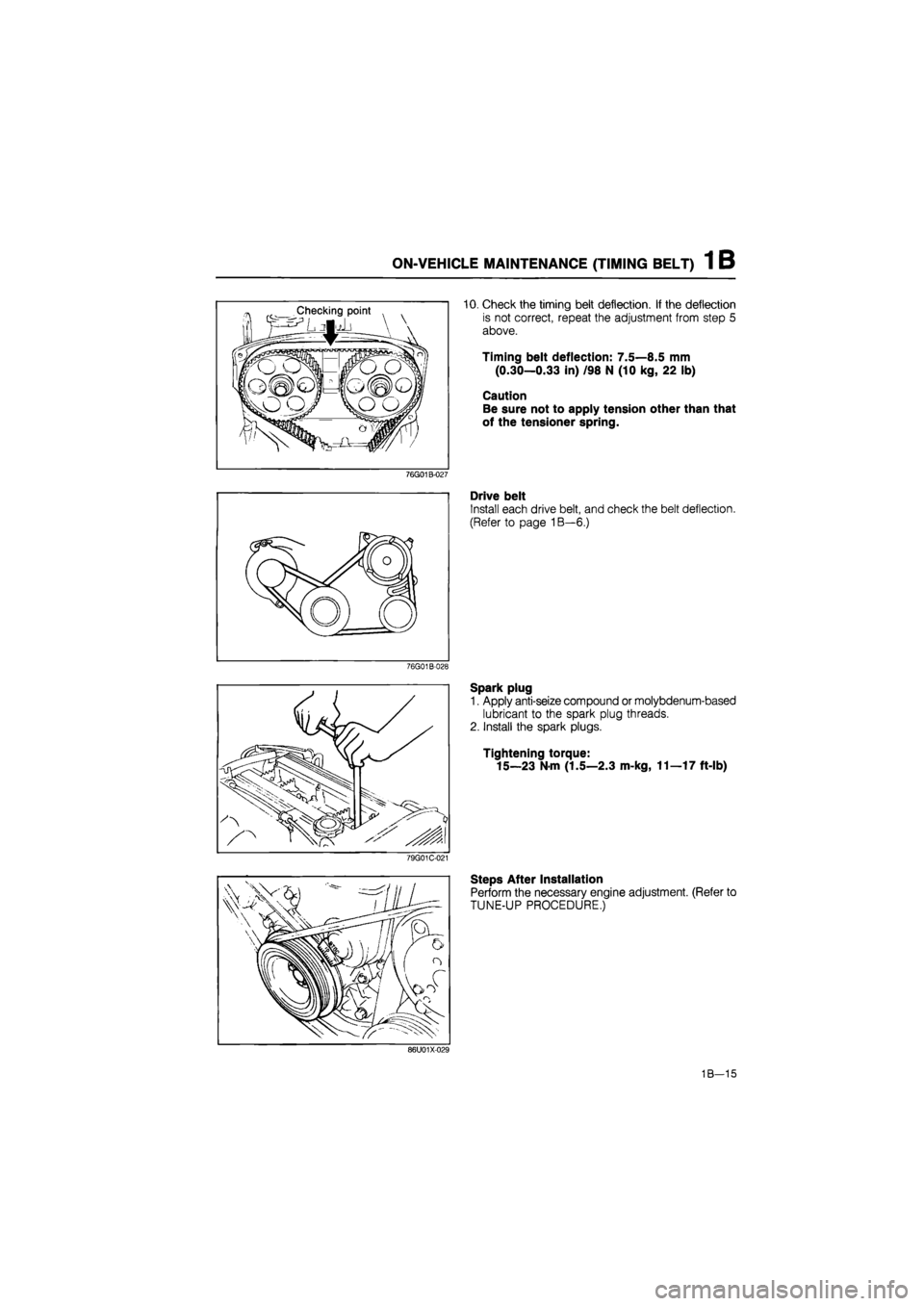
10. Check the timing belt deflection. If the deflection
is not correct, repeat the adjustment from step 5
above.
Timing belt deflection: 7.5â8.5 mm
(0.30â0.33 in) /98 N (10 kg, 22 lb)
Caution
Be sure not to apply tension other than that
of the tensioner spring.
76G01B-027
Drive belt
Install each drive belt, and check the belt deflection.
(Refer to page 1Bâ6.)
76G01B-028
Spark plug
1. Apply anti-seize compound or molybdenum-based
lubricant to the spark plug threads.
2. Install the spark plugs.
Tightening torque:
15â23
N
m (1.5â2.3 m-kg, 11â17 ft-lb)
79G01C-021
Steps After Installation
Perform the necessary engine adjustment. (Refer to
TUNE-UP PROCEDURE.)
86U01X-029
1Bâ15
Page 150 of 1865

1 B ON-VEHICLE MAINTENANCE (CYLINDER HEAD)
Installation
Install in the reverse order of removal referring to the installation note.
Note a) Position the hose clamp in the original location on the hose.
b) Squeeze the clamp lightly with large pliers to ensure a good fit.
Torque Specifications
8â12 N-m (80â120 cm-kg, 69â104
4â6 N-m (40â60 cm-kg, 35â52 in
15â23 N-m (1.5â2.3 m-kg, 11â17 ft-lb)
7â10 N-m (70â100 cm-kg, 61â87 In-lb)
â11 N-m (80â110 cm-kg, 69â95 In-lb)
37â52 N-m (3.8â5.3 m-kg. 27â38 ft-lb)
80â86 N-m (8.2â8.8 m-kj, 59â64 ft-lb)
~t/â- -19â30 N-m (1.9â3.1 m-kg, g^ 14-22 ft-lb)
\34â44
N-m (3.5â4.5 m-kg, ' 25â33 ft-lb)
19-30 N-m (1.9â3.1 m-kg, 14â22 ft-lb)
19â30 N-m (1.9â3.1 m-kg, 14â22 ft-lb)
37â52 N-m (3.8â5.3 m-kg, 27â38 ft-lb)
76G01A-112
1Bâ19
Page 151 of 1865

1 B ON-VEHICLE MAINTENANCE (CYLINDER HEAD)
Installation note
Cylinder head
1. Thoroughly remove all dirt and oil from the top of
the cylinder block with a rag.
2. Place a new cylinder head gasket in position.
86U01X-035
® © © (D ® 3. Set the cylinder head in place.
4. Apply engine oil to the bolt threads and seat faces.
5. Tighten the cylinder head bolts in two or three steps
in the order shown in the figure.
Tightening torque:
80â86
N
m (8.2â8.8 m-kg, 59â64 ft-lb)
86U01X-036
Cylinder head cover
1. Apply silicon sealant to the shaded area as shown
in the figure.
2. Install the cylinder head cover and gasket.
Tightening torque:
4â6 N-m (40â60 cm-kg, 35â52 in-lb)
76G01B-033
Timing belt
1. Align the mating marks of the camshaft pulleys with
the seal plate timing mark.
Note
For intake side camshaft pulley, align "I"
mark.
For exhaust side camshaft pulley, align "E"
mark.
2. Install the timing belt. (Refer to TIMING BELT of
ON-VEHICLE MAINTENANCE.)
76G01B-034
1Bâ20
Page 164 of 1865

DISASSEMBLY (CYLINDER BLOCK) 1 B
76G01B-048
76G01B-049
79G01C-050
Main bearing cap
Before removing the main bearing caps, clean the
bearings, main journals, and caps, and measure the
following points.
1. Crankshaft end play. (Refer to page 1Bâ52.)
2. Main journal oil clearance. (Refer to page 1Bâ51.)
Pilot bearing
Remove the pilot bearing from the crankshaft with the
SST
Piston and connecting rod
1. Before disassembling the piston and connecting
rod, check the oscillation torque as shown in the
figure.
If the large end does not drop by its own weight,
replace the piston or the piston pin.
2. Remove the piston pin with the SST.
76G01B-050
1 Bâ33
Page 171 of 1865

1 B INSPECTION AND REPAIR
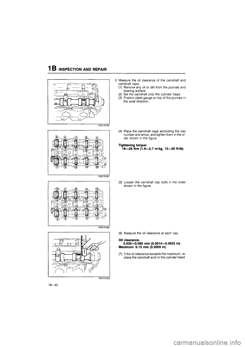
5. Measure the oil clearance of the camshaft and
camshaft caps.
(1) Remove any oil or dirt from the journals and
bearing surface.
(2) Set the camshaft onto the cylinder head.
(3) Position plasti-gauge on top of the journals in
the axial direction.
76G01B-060
(4) Place the camshaft caps according the cap
number and arrow, and tighten them in the or-
der shown in the figure.
Tightening torque:
18â26 N-m (1.8â2.7 m-kg, 13â20 ft-lb)
76G01B-061
(5) Loosen the camshaft cap bolts in the order
shown in the figure.
76G01B-062
(6) Measure the oil clearance at each cap.
Oil clearance:
0.035â0.085 mm (0.0014â0.0033 in)
Maximum: 0.15 mm (0.0059 in)
(7) If the oil clearance exceeds the maximum, re-
place the camshaft and/ or the cylinder head.
76G01B-063
1Bâ40
Page 179 of 1865

1 B ASSEMBLY (CYLINDER BLOCK)
ASSEMBLY
1. Clean all parts before reinstallation.
2. Apply new engine oil to all sliding and rotating parts.
3. Replace plain bearings if they are peeling, burned, or otherwise damaged.
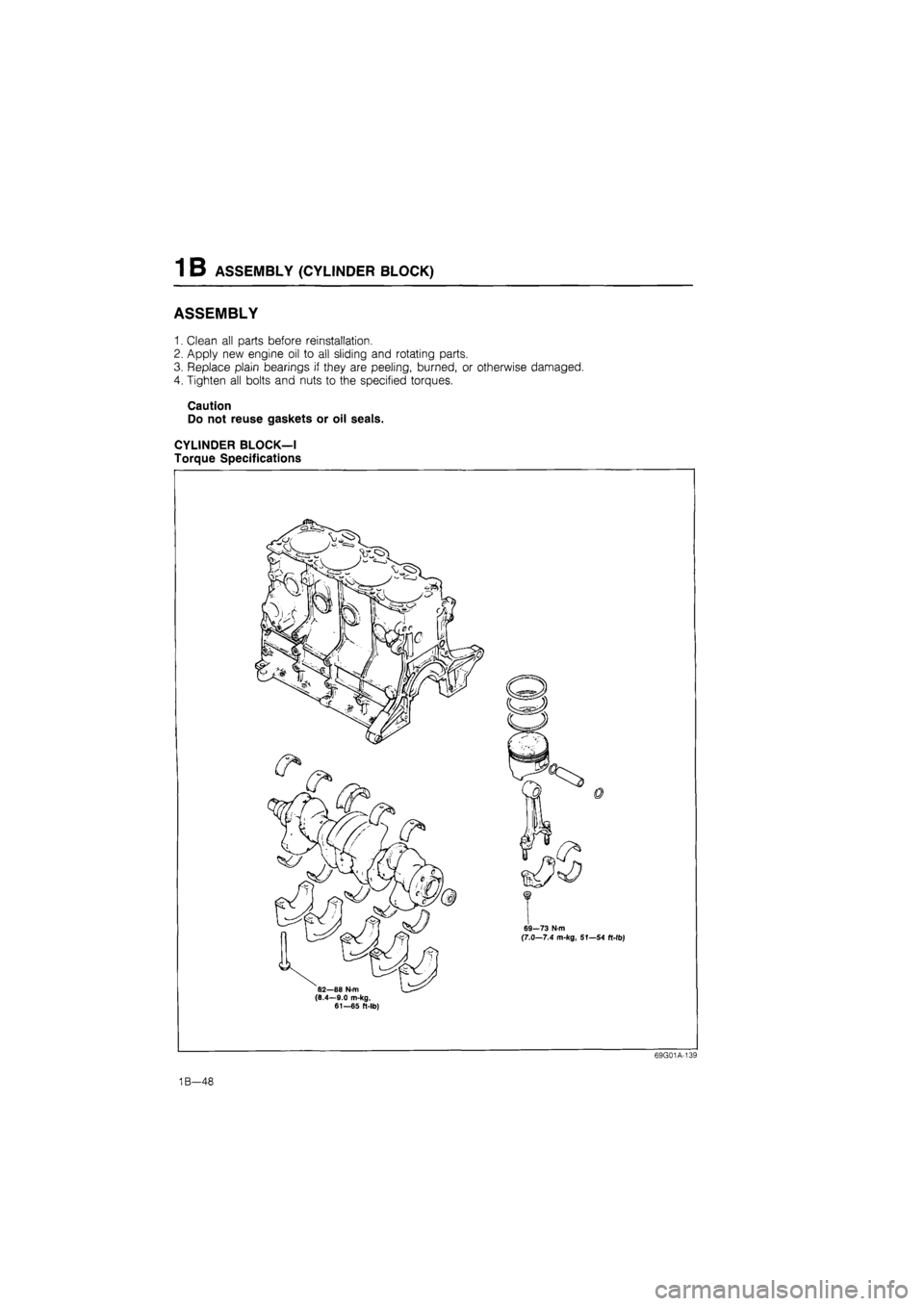
4. Tighten all bolts and nuts to the specified torques.
Caution
Do not reuse gaskets or oil seals.
CYLINDER BLOCKâI
Torque Specifications
69G01A-139
1Bâ48
Page 180 of 1865

ASSEMBLY (CYLINDER BLOCK) 1 B
76G01B-070
76G01B-071
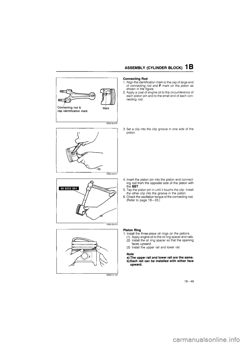
Connecting Rod
1. Align the identification mark to the cap of large end
of connecting rod and F mark on the piston as
shown in the figure.
2. Apply a coat of engine oil to the circumference of
each piston pin and to the small end of each con-
necting rod.
3. Set a clip into the clip groove in one side of the
piston.
4. Insert the piston pin into the piston and connect-
ing rod from the opposite side of the piston with
the SST .
5. Tap the piston pin in until it touchs the clip. Install
the other clip into the groove in the piston.
6. Check the oscillation torque of the connecting rod.
(Refer to page 1Bâ33.)
Piston Ring
1. Install the three-piece oil rings on the pistons.
(1) Apply engine oil to the oil ring spacer and rails.
(2) Install the oil ring spacer so that the opening
faces upward.
(3) Install the upper rail and lower rail.
Note
a) The upper rail and lower rail are the same.
b)Each rail can be installed with either face
upward.
69G01A-144
1Bâ49
Page 182 of 1865

ASSEMBLY (CYLINDER BLOCK) 1 B
Oil clearance inspection
(1) Remove any foreign material and oil from the
journals and bearings.
(2) Install the upper main bearings in the cylinder
block.
(3) Set the crankshaft into the cylinder block.
(4) Position the plasti-gauge on top of the journals
in the axial direction.
86U01X-122
(5) Install the main bearing caps along with the
lower main bearings according to the cap num-
ber and mark.
(6) Tighten the caps in two or three steps in the
order in the figure.
Tightening torque:
82â88 Nm (8.4â9.0 m-kg, 61â65 ft-lb)
Caution
Do not rotate the crankshaft when measuring
the oil clearances.
86U01X-123
(7) Remove the main bearing caps, and measure
the plasti-gauge at each journal at the widest
point for the smallest clearance, and at the nar-
rowest point for the largest clearance.
If the oil clearance exceeds specification, grind
the crankshaft and use undersize main bear-
ings. (Refer to page 1Bâ45.)
Oil clearance
No. 1, 2, 4, 5:
0.025â0.043 mm (0.0010â0.0017 in)
No. 3:
0.031â0.049 mm (0.0012â0.0019 in)
Maximum: 0.08 mm (0.0031 in)
Apply a liberal amount of engine oil to the main
bearings and main journals.
Install the crankshaft and the main bearing caps
according to the cap number and ^ mark.
86U01X-125
1Bâ51