MAZDA 626 1987 Workshop Manual
626 1987
MAZDA
MAZDA
https://www.carmanualsonline.info/img/28/57059/w960_57059-0.png
MAZDA 626 1987 Workshop Manual
Page 1584 of 1865
REAR COMBINATION LIGHTS 1 4
REPLACEMENT OF REAR COMBINATION LIGHT
LENS
1. Use a hot air blower to soften the "hot melt" (bond-
ing agent) around the lens.
86U14X-077
2. Remove the lens from the light housing by push-
ing the rear of the lens with a hammer handle or
round bar.
76U14X-034
3. Heat the light housing, and remove the "hot melt"
and any fragments of the lens.
Note
a) The "hot melt" should be reused if
possible.
b) If the "hot melt" can be reused, the follow-
ing step is unnecessary.
86U14X-078
4. Put Uni-sealer (8531 77 739) adhesive in the light
housing groove.
86U14X-079
14—33
Page 1585 of 1865
1 4 REAR COMBINATION LIGHTS
5. Fit the new lens onto the light housing. Press the
lens firmly so that it will adhere.
86U14X080
6. Immerse the combination light in water to check
for leaks.
76U14X-038
14—34
Page 1586 of 1865
LICENSE PLATE
LIGHT
AND CORGO ROOM LIGHT
1
4
LICENSE PLATE LIGHT AND CORGO ROOM LIGHT
REMOVAL AND INSTALLATION
1. Disconnect the negative battery cable.
2. Remove in the sequence shown in the figure.
3. Install in the reverse order of removal.
76G14X-011
Sedan and Coupe/MX-6
License plate light
1. Screws
2. Lens
3. Bulb 5W x 2
Back up light
4. End trim
5. Bulb 21W
6. Nuts
7. Rear finisher
Hatchback
Corgo room light
1. Lens
2. Switch and bulb assembly 5W
License plate light
3. Side trim
4. Lower trim
5. End trim
6. Screws
7. Lens
8. Bulb 5W x 2
9. Rear finisher
14-35
Page 1587 of 1865
1 4 INTERIOR
LIGHT AND
MAP LIGHT
INTERIOR LIGHT AND MAP LIGHT
REMOVAL AND INSTALLATION
1. Disconnect the negative battery cable.
2. Remove in the sequence shown in the figure.
3. Install in the reverse order of removal.
Map light
86U14X-082
Interior Light Map Light
1. Lens 1. Lens
2. Bulb 10W 2. Bulb 8W
14-36
Page 1589 of 1865
1 4 MOLDING AND GARNISH
WINDSHIELD MOLDING
Removal and Installation
1. Remove the windshield molding. (Refer to page
14-48)
2. Install the windshield molding. (Refer to page
14-51)
76G14X035
WINDSHIELD LOWER MOLDING
Removal and Installation
1. Remove the wiper arms.
2. Remove the lower molding screws and the lower
molding.
3. Install in the reverse order of removal.
86U14X-086
DRIP MOLDING
Removal and Installation
1. Insert a screwdriver between the roof rail and drip
molding and slightly loosen the end of the molding.
Note
Be careful not to scratch the molding.
2. Remove the molding by twisting upward with both
hands.
3. Install in the reverse order of removal.
86U14X-087
BELTLINE MOLDING
Removal and Installation
1. Remove the door mirror.
2. Remove the screw from the end of the beltline
molding, then pull the molding up to remove it.
3. Install in the reverse order of removal.
86U14X-088
14-38
Page 1601 of 1865

14 WINDSHIELD GLASS
Repair seal
Dam
_5 mm
.(0.19
11 mm
(0.43 in)
6. Prepare the nozzle of the sealant gun so that it has
a flange that can run along the edge of the glass,
and a V from which the sealant can flow. Once the
primer is dry, apply the sealant around the entire
circumference to fill the gap between the dam and
the edge of the glass with a ridge of sealant 11
mm (0.43 in) high.
Keep the bead of sealant smooth and even,
reshaping it where necessary with a spatula.
86U14X-11E
7BU14X-026
76G14X-044
Replenished section
with sealing agent
— Glass
7. Lift the glass into place. Push it in lightly toward
the vehicle to compress the sealant.
Caution
Open the windows to prevent the glass from
being pushed out by air pressure if a door is
closed.
Hardening time of repair seal
Temperature Surface hardening
time
Time required until car
can be put in service
5°C (41 °F) Approx. 1.5 hrs 12 hrs
20°C (68°F) Approx. 1 hr 4 hrs
35°C (95°F) Approx. 10 min. 2 hrs
8. Use a scraper to smooth away any sealant that
oozes out. Add more sealant to any points of poor
contact.
9. Check for water leaks. If a leak is found, wipe the
water off well and add repair seal (B001 77 739)
where needed.
Spacer
86U14X-120
14-50
Page 1618 of 1865
HEADLINER 14
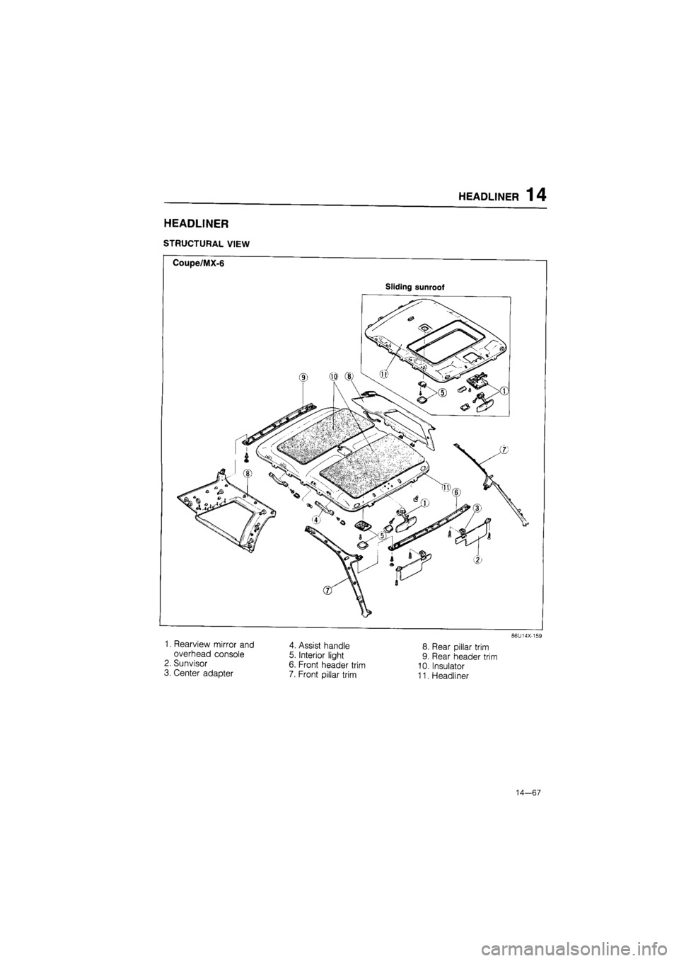
HEADLINER
STRUCTURAL VIEW
Coupe/MX-6
Sliding sunroof
1. Rearview mirror and
overhead console
2. Sunvisor
3. Center adapter
4. Assist handle
5. Interior light
6. Front header trim
7. Front pillar trim
8. Rear pillar trim
9. Rear header trim
10. Insulator
11. Headliner
86U14X-159
14—67
Page 1619 of 1865
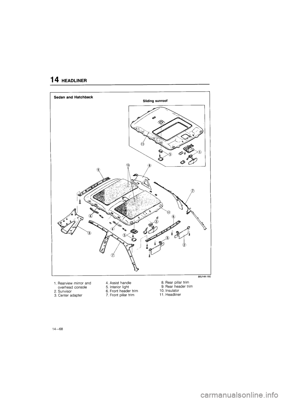
14 HEADLINER
Sedan and Hatchback
Sliding sunroof
86U14X-160
1. Rearview mirror and
overhead console
2. Sunvisor
3. Center adapter
4. Assist handle
5. Interior light
6. Front header trim
7. Front pillar trim
8. Rear pillar trim
9. Rear header trim
10. Insulator
11. Headliner
14—68
Page 1620 of 1865
HEADLINER 14
REMOVAL
1. Remove the overhead console cover.
2. Remove the rearview mirror.
3. Remove the overhead console mounting screws.
4. Disconnect the connectors and remove the over-
head console.
86U14X-161
69G14X-241
5. Remove the sunvisors.
6. Remove the center adapters.
7. Remove the interior light lens with a protected small
screwdriver.
86U14X-162
8. Remove the interior light mounting screws and dis-
connect the connector.
9. Remove the interior light.
86U14X-163
14—69
Page 1623 of 1865
14 HEADLINER
18. Remove the fasteners and remove the headliner.
86U14X-172
INSTALLATION
Install in the reverse order of removal, noting the fol-
lowing.
Note
Align the trim and clip positions, then install
the clips by striking them lightly.
86U14X-173
14—72


