sensor MAZDA 626 1987 Workshop Manual
[x] Cancel search | Manufacturer: MAZDA, Model Year: 1987, Model line: 626, Model: MAZDA 626 1987Pages: 1865, PDF Size: 94.35 MB
Page 1685 of 1865

15 METER
Fuel transfer unit (only 4WS model)
1. Remove the fuel transfer unit referring to section 4.
2. Remove the connector from the fuel transfer unit.
3. Connect an ohmmeter between "b" and "d" ter-
minal of the connector.
4. Move the unit arm slowly from point (F) to point
(E), and read the resistance values.
5. If not as specified, replace the unit.
86U15X-044
iel tank unit (only 4WS model)
Remove the fuel tank unit.
Remove the connector from the fuel tank unit.
Connect an ohmmeter between "d" terminal of the
connector and fuel tank unit cover.
Move the unit arm slowly from point (F) to point
(E) and read the resistance values.
If not as specified, replace the unit.
86U15X-045
Water Thermo Sensor
1. Remove the sensor.
2. Place the sensor in water along with a ther-
mometer.
3. Heat the water gradually, and check the resistance
of the sensor with an ohmmeter.
4. If the resistance is not as specified, replace the
sensor.
Resistance: 49.3—57.7 Q at 80°C (176°F)
76G15X-089
15-30
Page 1694 of 1865

WARNING AND SENDER 15
Coolant Level Warning Light
OK
Repair harness (Meter
to
coolant level sensor).
76G15X093
INSPECTION
Brake Fluid Level Sensor
1. Check for continuity of the sensor with an
ohmmeter.
Float level Continuity
Below
min
Yes
Above
min
No
2. If continuity is not as specified, replace the sensor.
86U15X-065
86U14X-066
Parking Brake Switch
1. Check for continuity between (R) terminal and a
body ground with an ohmmeter.
Lever Continuity
Pulled one notch Yes
Released No
2. If continuity is not as specified, adjust the switch
or replace the switch.
15—39
Page 1695 of 1865

15 WARNING AND SENDER
86U15X-068
86U15X069
86U15X-070
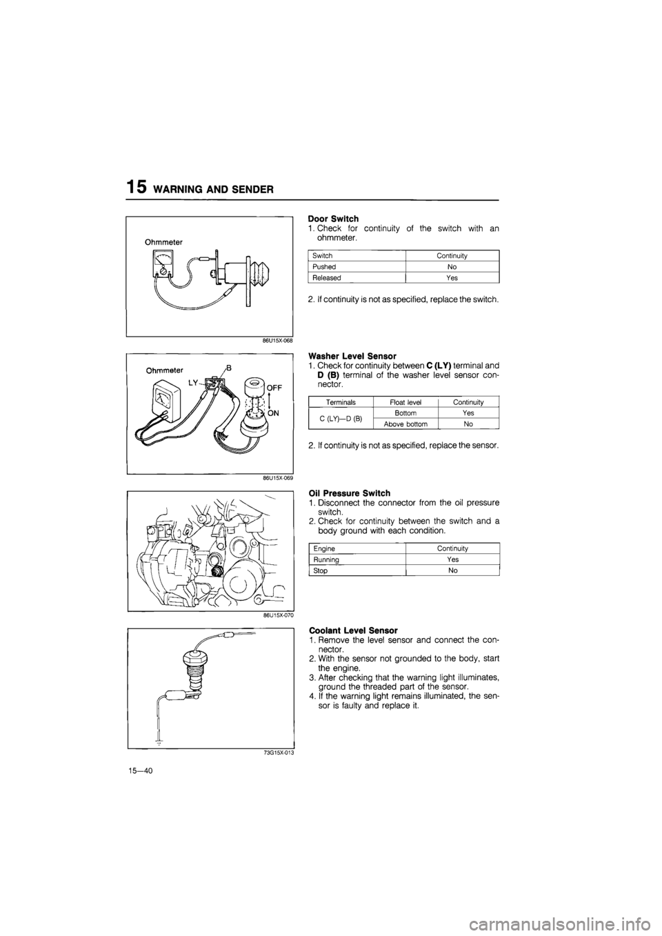
Door Switch
1. Check for continuity of the switch with an
ohmmeter.
2. If continuity is not as specified, replace the switch.
Washer Level Sensor
1. Check for continuity between C (LY) terminal and
D (B) terminal of the washer level sensor con-
nector.
Oil Pressure Switch
1. Disconnect the connector from the oil pressure
switch.
2. Check for continuity between the switch and a
body ground with each condition.
Coolant Level Sensor
1. Remove the level sensor and connect the con-
nector.
2. With the sensor not grounded to the body, start
the engine.
3. After checking that the warning light illuminates,
ground the threaded part of the sensor.
4. If the warning light remains illuminated, the sen-
sor is faulty and replace it.
73G15X-013
15—40
Engine Continuity
Running Yes
Stop No
Terminals Float level Continuity
C (LY)—D
(B)
Bottom Yes C (LY)—D
(B)
Above bottom No
2. If continuity is not as specified, replace the sensor.
Page 1739 of 1865

1 5 CRUISE CONTROL SYSTEM
ON-VEHICLE INSPECTION (USING ACC CHECKER 49 9200 010)
76G15X-072
Note:
When checking the actuator on '88 models with EC-AT using this checker, the checker
should be modified as shown below in order to avoid damage of the EC-AT control unit.
Modification Procedure
1. Cut the wire at terminal no.6 indicated on ACC
checker connector.
2. Tape exposed end of wire cut in step 1 as shown.
This modification does not affect the usage of the ACC
checker except when used on the '81 RX-7 and 626
models. When the modified ACC checker is used on
these models, use a jumper wire and jump across
terminal no.6 to 3 indicated on ACC checker connec-
tor as shown.
Function of the ACC CHECKER
A. Check lights
Each item is verified by a check light, as described below.
Check light Check items
MAIN SW.
Ignition switch, fuse, main switch and associated wiring harness terminals and con-
nectors.
ACTUATOR—VAC
VAC coil continuity
in
the actuator and associated harness.
ACTUATOR—VENT 2
VENT
2
coil continuity
in
the actuator and associated harness.
ACTUATOR—VENT 1
VENT
1
coil continuity
in
the actuator and associated harness.
CLUTCH/BRAKE SW.
Clutch switch (M/T vehicles only), brake switch and associated harness
COMBINATION/INH. SW.
"SET", "COAST" and "RESUME" positions
in
the combination switch, inhibitor
switch (A/T vehicles only), and associated harness.
GENERATOR
Speed sensor output and associated harness.
76U15X-193
15-84
Page 1742 of 1865

CRUISE CONTROL SYSTEM 1 5
CHECK LIGHTS (correct response)
ACTUATOR £
5 (O
W X
CHECK ITEMS AND CONDITIONS £ <0 z
VAC
CM I-1-z
Ul * < IE ffl X o V-
z o F < z ta
DC O 1-< DC Ui
TROUBLESHOOTING
(INCORRECT RESPONSE)
< S VAC UJ > < > -1 o o o UJ O
8. START THE ENGINE
• Shift lever to "N" position (A/T) O O O o X
A/T
O M/T X
O or X —
9. ACTUATOR OPERATION: (EGI model only) • After engine is started, set the slide switch "L" or "H". Then turn on check switch (keep in "D" position) Note: Engine speed should in-crease to 2,000—3,000 rpm. If over 4,000 rpm release the switch immediately.
o
X
1
o
X X X
A/T O M/T X
O or X
If engine speed does not come up to and remain
in
the
2,000
to
3,000
rpm. range, check the actuator and as-sociated harness.
10. SPEED SENSOR OUTPUT
Keeping idling condition, drive ve-
hicle slowly. o o 0 o X X 0 1 X
If GENERATOR LIGHT does not flash, trouble may be with speed sensor and associated harness.
76U15X-199
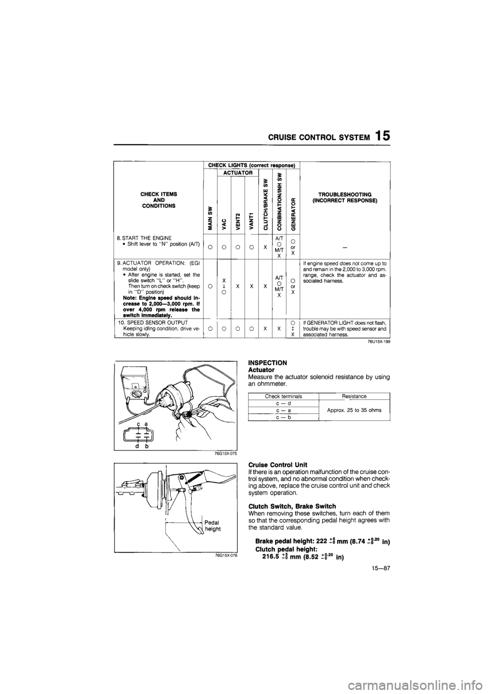
INSPECTION
Actuator
Measure the actuator solenoid resistance by using
an ohmmeter.
Check terminals Resistance
c-d
Approx. 25 to 35 ohms c — a Approx. 25 to 35 ohms
c — b
Approx. 25 to 35 ohms
76G15X-075
Cruise Control Unit
If there is an operation malfunction of the cruise con-
trol system, and no abnormal condition when check-
ing above, replace the cruise control unit and check
system operation.
Clutch Switch, Brake Switch
When removing these switches, turn each of them
so that the corresponding pedal height agrees with
the standard value.
76G15X-076
Brake pedal height: 222 ±1 mm (8.74 1820
Clutch pedal height:
216.5 ±8 mm (8.52 ±820 In)
in)
15-87
Page 1743 of 1865

1 5 CRUISE CONTROL SYSTEM
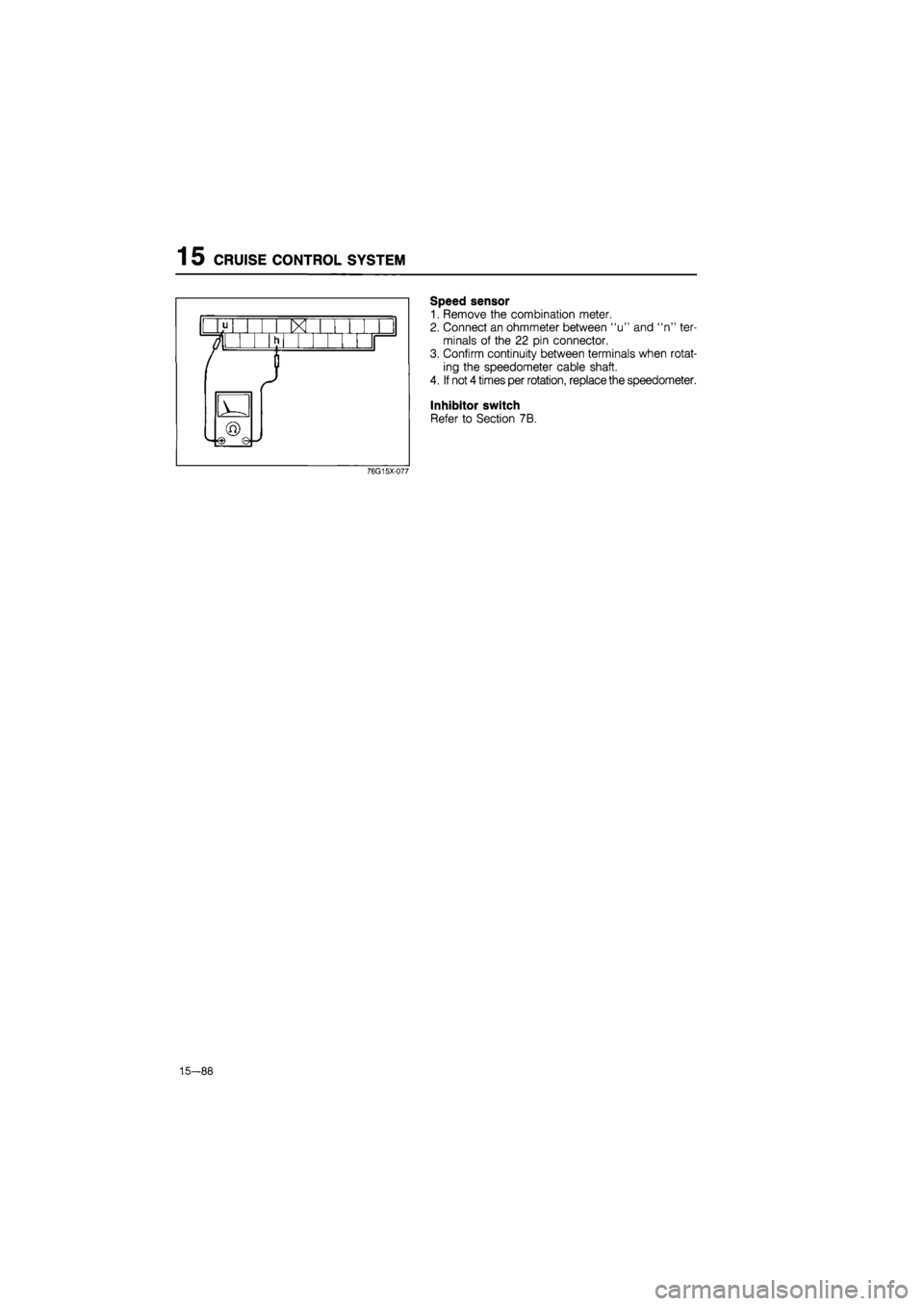
Speed sensor
1. Remove the combination meter.
2. Connect an ohmmeter between "u" and "n" ter-
minals of the 22 pin connector.
3. Confirm continuity between terminals when rotat-
ing the speedometer cable shaft.
4. If not 4 times per rotation, replace the speedometer.
Inhibitor switch
Refer to Section 7B.
76G15X-077
—88
Page 1749 of 1865

1 5 AUTO ADJUSTING SUSPENSION (AAS)
AUTO ADJUSTING SUSPENSION (AAS)
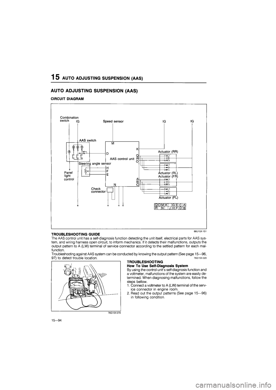
CIRCUIT DIAGRAM
Combination switch iq Speed sensor
M
Panel light
control
AAS control unit
Steering angle sensor
H
N
Check connector
IG IG
Actuator (RR)
-P-Sl
-t-^J
—Pwsl
Actuator (RL)
Actuator (FR) P5fl
+
Actuator (FL)
QO M K GIE C A
ft N J HI F D B
86U15X-151
TROUBLESHOOTING GUIDE
The AAS control unit has a self-diagnosis function detecting the unit itself, electrical parts for AAS sys-
tem, and wiring harness open circuit, to inform mechanics. If it detects their malfunctions, outputs the
output pattern to A (LW) terminal of service connector according to the settled pattern for each mal-
function.
Troubleshooting against AAS system can be conducted by knowing the output pattern (See page 15—96,
97) to detect trouble location. 76gisx-o2o
TROUBLESHOOTING
How To Use Self-Diagnosis System
By using the control unit's self-diagnosis function and
a voltmeter, malfunctions of the system are easily de-
termined. When diagnosing malfunctions, follow the
steps bellow.
1. Connect a voltmeter to A (LW) terminal of the serv-
ice connector in engine room.
2. Read out the output patterns (See page 15—96)
in following condition.
76G15X-079
15—94
Page 1751 of 1865

1 5 AUTO ADJUSTING SUSPENSION (AAS)
Condition Output pattern Malfunction Flow chart
No.
A
Set steering wheel
in
straight ahead position
0.5 sec
4.4V
n\/
2 sec
Vehicle speed sensor
or
wiring harness (Meter
—
Control unit)
AAS-1
Refer
to
page
15—98
A
Set steering wheel
in
straight ahead position
Vehicle speed sensor
or
wiring harness (Meter
—
Control unit)
AAS-1
Refer
to
page
15—98
A
Set steering wheel
in
straight ahead position
0.5 secO.!
4.4V
nv
i sec
2
sec
— <—i i— -
Steering wheel angle sen-
sor
or
wiring harness (An-
gle sensor
—
Control unit)
AAS-2
Refer
to
page
15-98
A
Set steering wheel
in
straight ahead position
-
Steering wheel angle sen-
sor
or
wiring harness (An-
gle sensor
—
Control unit)
AAS-2
Refer
to
page
15-98
A
Set steering wheel
in
straight ahead position
nv
Normal operation or wiring
harness (Fuse box
—
Con-
trol unit, control unit
—
Body ground)
AAS-3
Refer
to
page
15-99
A
Set steering wheel
in
straight ahead position
Normal operation or wiring
harness (Fuse box
—
Con-
trol unit, control unit
—
Body ground)
AAS-3
Refer
to
page
15-99
B
Turn the steering wheel
right and left
0.5 sec
4.4V
n\/
2 sec
—
Vehicle speed sensor
or
wiring harness (Meter
—
Control unit)
AAS-1
Refer
to
page
15-98
B
Turn the steering wheel
right and left
Vehicle speed sensor
or
wiring harness (Meter
—
Control unit)
AAS-1
Refer
to
page
15-98
B
Turn the steering wheel
right and left
0.5 sec 0
4.4V""-
.5 se c 2 se
-
Normal operation
—
B
Turn the steering wheel
right and left Normal operation
—
B
Turn the steering wheel
right and left
ov
Wiring harness (Fuse box
— Control unit, Control unit
— Body ground) See page
AAS-4
Refer
to
page
15—99
B
Turn the steering wheel
right and left
Wiring harness (Fuse box
— Control unit, Control unit
— Body ground) See page
AAS-4
Refer
to
page
15—99
C
Change the switch from
NORMAL to SPORT
or
from SPORT
to
NORMAL
0.5 sec
4.4V-""
_
n
Normal operation
—
C
Change the switch from
NORMAL to SPORT
or
from SPORT
to
NORMAL
Normal operation
—
C
Change the switch from
NORMAL to SPORT
or
from SPORT
to
NORMAL
0.5 sec 0
4.4V
nv
.5 se c
—
2 se
C
i—1 i—i
Front actuators
or
wiring
harness (Control unit
—
Front right
or
left actuator
AAS-5
Refer
to
page
15-100
C
Change the switch from
NORMAL to SPORT
or
from SPORT
to
NORMAL
Front actuators
or
wiring
harness (Control unit
—
Front right
or
left actuator
AAS-5
Refer
to
page
15-100
C
Change the switch from
NORMAL to SPORT
or
from SPORT
to
NORMAL
0.5 sec 0
4.4V*-
n\/
.5 se c
— r— —
2 sec
—1
Rear actuators
or
wiring
harness (Control unit
—
Rear right
or
left actuator
AAS-6
Refer
to
page
15-101
C
Change the switch from
NORMAL to SPORT
or
from SPORT
to
NORMAL
Rear actuators
or
wiring
harness (Control unit
—
Rear right
or
left actuator
AAS-6
Refer
to
page
15-101
15-96
Page 1752 of 1865

AUTO ADJUSTING SUSPENSION (AAS) 1 5
C
(Cont'd)
Operate
the
vehicle
at
above
15 km/h (9.3
mph) on
a
chassis roller
OV-
4.4V
0V-
4.4V
OV-
OV
AAS switch
or
wiring har-
ness (Fuse box
—
Control
box and AAS switch, AAS
switch
—
Control box and
Body ground)
Normal operation
Speed sensor
or
Steering
wheel angle sensor
or
wir-
ing harness (Control unit
—
Meter, Control unit
—
An-
gle sensor)
Speed sensor
or
Wiring
harness (Control unit
—
Meter, Fuse box
—
Control
unit, Control unit
—
Body
ground)
76G15X-080
15-97
Page 1753 of 1865

1 5 AUTO ADJUSTING SUSPENSION
Inspection of circuit
OK
Check
for
continuity between
1U
(GR) terminal
of
the meter connector and
M
(GR) terminal
of
the control unit connector.
Repair the wiring harness (Control unit
to
Meter).
OK
Replace the control unit.
76G15X-081
AAS-2
Failure
of
steering wheel angle sensor
or wiring harness (Angle sensor
—
Control unit)
I
Disconnect the control unit connector, and check
the
resistance between the terminals with
an
ohmmeter
when steering wheel
in
straight ahead position.
Terminal Resistance
A(G)
-
D(GW) ADDrox.
25 kfi
A(G)
-
C(GY) Approx.
50 kfl
C(GY^
-
D(G\M ADorox.
25 kfi
OK
Replace the control unit.
76G15X-082
15-98