change time MAZDA 626 1987 Workshop Manual
[x] Cancel search | Manufacturer: MAZDA, Model Year: 1987, Model line: 626, Model: MAZDA 626 1987Pages: 1865, PDF Size: 94.35 MB
Page 15 of 1865

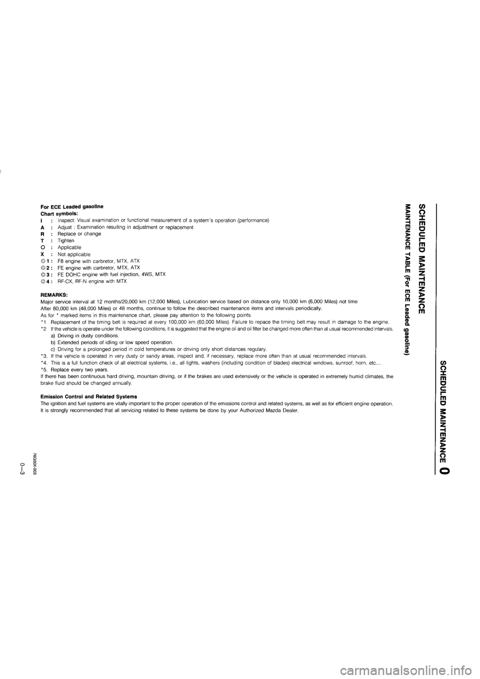
For ECE Leaded gasoline
Chart symbols:
I
A
R
T
O
X
Inspect: Visual examination or functional measurement of a system's operation (performance)
Adjust : Examination resulting in adjustment or replacement
Replace or change
Tighten
Applicable
Not applicable
F8 engine with carbretor, MTX, ATX
FE engine with carbretor, MTX, ATX
FE DOHC engine with fuel injection, 4WS, MTX
RF-CX, RF-N engine with MTX
REMARKS:
Major service interval at 12 months/20,000 km (12,000 Miles), Lubrication service based on distance only 10,000 km (6,000 Miles) not time
After 80,000 km (48,000 Miles) or 48 months, continue to follow the described maintenance items and intervals periodically.
As for * marked items in this maintenance chart, please pay attention to the following points.
*1 Replacement of the timing belt is required at every 100,000 km (60,000 Miles). Failure to repace the timing belt may result in damage to the engine.
*2 If the vehicle is operatie under the following conditions, it is suggested that the engine oil and oil filter be changed more often than at usual recommended intervals.
a) Driving in dusty conditions.
b) Extended periods of idling or low speed operation.
c) Driving for a prolonged period in cold temperatures or driving only short distances regulary.
*3. If the vehicle is operated in very dusty or sandy areas, inspect and, if necessary, replace more often than at usual recommended intervals.
*4. This is a full function check of all electrical systems, i.e., all lights, washers (including condition of blades) electrical windows, sunroof, horn, etc....
*5. Replace every two years.
If there has been continuous hard driving, mountain driving, or if the brakes are used extensively or the vehicle is operated in extremely humid climates, the
brake fluid should be changed annually.
>
Z H m >
o m
H >
CD r-m
o m
m O m
(D o> Q. ® a
(Q 0) <0 o
m a
o m
c/> o x m a
Emission Control and Related Systems
The ignition and fuel systems are vitally important to the proper operation of the emissions control and related systems, as well as for efficient engine operation.
It is strongly recommended that all servicing related to these systems be done by your Authorized Mazda Dealer.
m a
m z >
z o m
G)
Page 21 of 1865

r
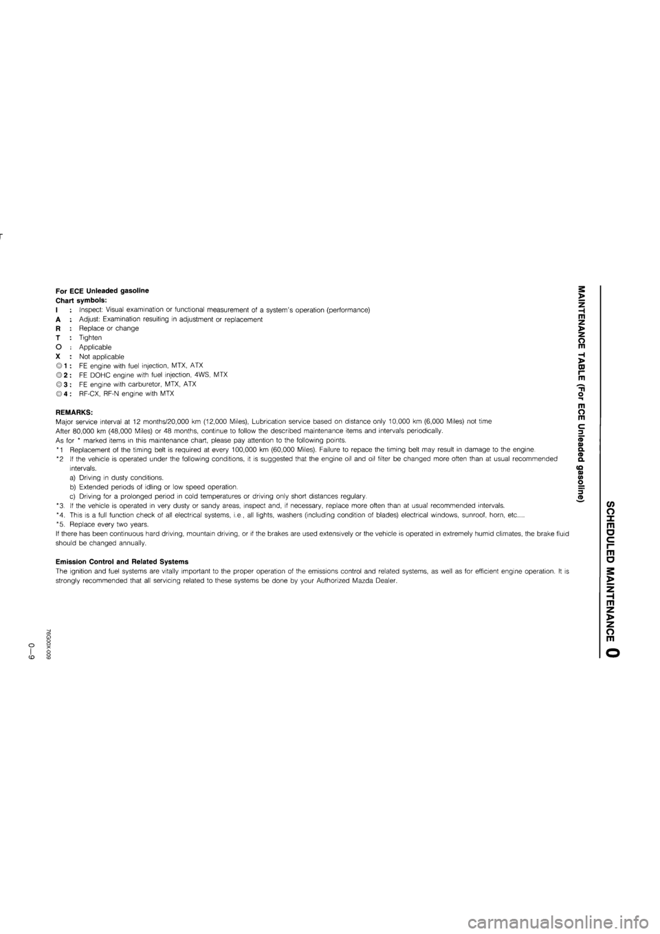
For ECE Unleaded gasoline
Chart symbols:
I
A
R
T
O
X
Inspect: Visual examination or functional measurement of a system's operation (performance)
Adjust: Examination resulting in adjustment or replacement
Replace or change
Tighten
Applicable
Not applicable
FE engine with fuel injection, MTX, ATX
FE DOHC engine with fuel injection, 4WS, MTX
FE engine with carburetor, MTX, ATX
RF-CX, RF-N engine with MTX
REMARKS:
Major service interval at 12 months/20,000 km (12,000 Miles), Lubrication service based on distance only 10,000 km (6,000 Miles) not time
After 80,000 km (48,000 Miles) or 48 months, continue to follow the described maintenance items and intervals periodically.
As for * marked items in this maintenance chart, please pay attention to the following points.
*1 Replacement of the timing belt is required at every 100,000 km (60,000 Miles). Failure to repace the timing belt may result in damage to the engine.
*2 If the vehicle is operated under the following conditions, it is suggested that the engine oil and oil filter be changed more often than at usual recommended
intervals.
a) Driving in dusty conditions.
b) Extended periods of idling or low speed operation.
c) Driving for a prolonged period in cold temperatures or driving only short distances regulary.
*3. If the vehicle is operated in very dusty or sandy areas, inspect and, if necessary, replace more often than at usual recommended intervals.
*4. This is a full function check of all electrical systems, i.e., all lights, washers (including condition of blades) electrical windows, sunroof, horn, etc....
*5. Replace every two years.
If there has been continuous hard driving, mountain driving, or if the brakes are used extensively or the vehicle is operated in extremely humid climates, the brake fluid
should be changed annually.
Emission Control and Related Systems
The ignition and fuel systems are vitally important to the proper operation of the emissions control and related systems, as well as for efficient engine operation. It is
strongly recommended that all servicing related to these systems be done by your Authorized Mazda Dealer.
>
Z H m z >
o m
H >
DJ r~ m
m o m
c 3
(/> O X m o c i-m
o
m z >
z o m
CD
Page 852 of 1865

7A ASSEMBLY
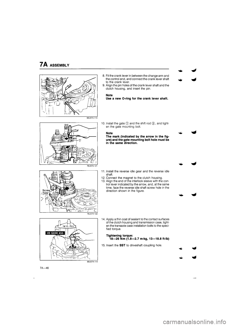
8. Fit the crank lever in between the change arm and
the control end, and connect the crank lever shaft
to the crank lever.
9. Align the pin holes of the crank lever shaft and the
clutch housing, and insert the pin.
Note
Use a new O-ring for the crank lever shaft.
86U07A-113
10. Install the gate © and the shift rod ©, and tight-
en the gate mounting bolt.
Note
The mark (indicated by the arrow in the fig-
ure) and the gate mounting bolt hole must be
in the same direction.
76U07A-121
11. Install the reverse idle gear and the reverse idle
shaft.
12. Connect the magnet to the clutch housing.
13. Align the end of the interlock sleeve with the con-
trol lever indicated by the arrow, and, at the same
time, face the reverse idle shaft screw hole in the
direction shown in the figure.
76U07A-122
14. Apply a thin coat of sealant to the contact surfaces
of the clutch housing and transmission case, tight-
en the transaxle case installation bolts to the speci-
fied torque.
Tightening torque:
18—26 N m (1.8—2.7 m-kg, 13—18.8 ft-lb)
15. Insert the SST to driveshaft coupling hole.
7A-46
Page 1419 of 1865

POWER BRAKE UNIT 1 1
86U11X-038
0
o
X
\ V^ Third
Second
^ First
86U11X-039
O X
fiSy
V
86U11X-040
Pedal-depression Pre!tur!9au9e
force gauge
^Intake manifold
86U11X-041
POWER BRAKE UNIT
FUNCTION CHECK
Simple Method
First step
1. With the engine stopped, depress the pedal a few
times.
2. With the pedal depressed, start the engine
3. If immediately after the engine starts the pedal
moves down slightly, the unit is operating.
Second step
1. Start the engine.
2. Stop the engine after it has run for
1
or 2 minutes.
3. Depress the pedal with the usual force.
4.
If
the first pedal stroke is long and becomes short-
er with subsequent strokes, the unit is operating.
5. If a problem is found, inspect for damage of the
check valve or vacuum hose, and examine the in-
stallation condition. Repair if necessary, and inspect
it once again.
Third step
1. Start the engine.
2. Depress the pedal with the usual force.
3. Stop the engine with the pedal still depressed.
4. Hold the pedal down for about 30 seconds.
5. If the pedal height does not change, the unit is
operating.
6. If there is a problem, check for damage to the
check valve or vacuum hose, and check the con-
nection. Repair if necessary, and check once
again.
If the nature of the problem is still not clear after fol-
lowing the 3 steps above, follow the more detailed
check described in "Method using tester".
Method Using Tester
Connect a pressure gauge, vacuum gauge, and ped-
al depression force gauge as shown in the figure. Af-
ter bleeding the air from the pressure gauge, conduct
the test as described in the 3 steps below.
Note
Use commercially available gauges and ped-
al depression force gauge.
11—27