relay MAZDA 626 1987 User Guide
[x] Cancel search | Manufacturer: MAZDA, Model Year: 1987, Model line: 626, Model: MAZDA 626 1987Pages: 1865, PDF Size: 94.35 MB
Page 463 of 1865

FUEL AND EMISSION
CONTROL SYSTEMS
(FUEL INJECTION FE)
OUTLINE 4B— 2
SYSTEM DIAGRAM 4B— 2
COMPONENT LOCATION 4B— 3
VACUUM HOSE ROUTING
DIAGRAM 4B— 5
SPECIFICATIONS 4B— 6
TROUBLESHOOTING GUIDE 4B— 7
TROUBLESHOOTING
PROCEDURE 4B— 7
TROUBLESHOOTING WITH SST.... 4B— 9
INSPECTION PROCEDURE 4B—10
AFTER-REPAIR PROCEDURE 4B—10
PRINCIPLE OF CODE CYCLE 4B—12
CODE NUMBER 4B—13
SWITCH MONITOR FUNCTION 4B—25
INSPECTION PROCEDURE 4B—26
IDLE SPEED 4B—29
IDLE MIXTURE 4B—29
INTAKE AIR SYSTEM 4B—30
COMPONENT DESCRIPTIONS 4B—30
REMOVAL 4B—31
PARTS INSPECTION 4B—32
INSTALLATION 4B—34
IDLE-UP SYSTEM 4B—35
COMPONENT DESCRIPTIONS 4B—36
TROUBLESHOOTING 4B—37
AIR VALVE 4B—38
AIR BYPASS SOLENOID VALVE ... 4B—39
FUEL SYSTEM 4B—42
COMPONENT DESCRIPTIONS 4B—43
TROUBLESHOOTING 4B—44
FUEL PRESSURE RELEASE AND
SERVICING FUEL SYSTEM 4B—45
MULTI-PRESSURE TESTER 4B—46
FUEL PRESSURE 4B—48
FUEL PUMP 4B—49
PULSATION DAMPER 4B—50
INJECTOR 4B—51
PRESSURE REGULATOR
CONTROL SYSTEM 4B—53
COMPONENT DESCRIPTIONS 4B—54
TROUBLESHOOTING 4B—55
REPLACEMENT 4B—57
FUEL TANK 4B—61
DECELERATION CONTROL
SYSTEM 4B—64
COMPONENT DESCRIPTIONS 4B—65
TROUBLESHOOTING 4B—66
AIR INJECTION SYSTEM 4B—68
COMPONENT DESCRIPTIONS 4B—68
TROUBLESHOOTING 4B—69
EXHAUST GAS RECIRCULATION
(EGR) SYSTEM 4B—71
COMPONENT DESCRIPTIONS 4B—71
TROUBLESHOOTING 4B—72
EVAPORATIVE EMISSION
CONTROL (EEC) SYSTEM 4B—74
COMPONENT DESCRIPTIONS 4B—74
TROUBLESHOOTING 4B—75
POSITIVE CRANKCASE
VENTILATION (PCV) SYSTEM 4B—80
COMPONENT DESCRIPTION 4B—80
EXHAUST SYSTEM 4B—81
REMOVAL AND INSTALLATION ... 4B—82
INSPECTION 4B—82
CONTROL SYSTEM 4B—83
RELATIONSHIP CHART 4B—84
EGI MAIN FUSE 4B—86
MAIN RELAY 4B—86
CIRCUIT OPENING RELAY 4B—86
ENGINE CONTROL UNIT 4B—87
NEUTRAL SWITCH 4B—91
CLUTCH SWITCH 4B—91
BRAKE LIGHT SWITCH 4B—91
P/S PRESSURE SWITCH 4B—92
INHIBITOR SWITCH 4B—92
E/L CONTROL UNIT 4B—93
AIR FLOW METER 4B—94
THROTTLE SENSOR 4B—95
WATER THERMO SENSOR 4B—97
WATER THERMO SWITCH 4B—97
OXYGEN SENSOR 4B—98
ATMOSPHERIC PRESSUFfE
SENSOR 4B—99
76G04B-001
Page 472 of 1865

4B TROUBLESHOOTING WITH SST
INSPECTION PROCEDURE
1. Connect the SST to the check connector, (Green,
6-pin) and the negative battery terminal.
2. Set the select switch to position A.
Note
The check connector is located at the rear of
the left side wheel housing.
86U04A-011
Test connector: Green (1 pin)
3. Ground the test connector (Green, 1-pin) with a
jumper wire.
Note
The test connector is located near the Self-
Diagnosis Checker check connector.
86U04A-012
OO
uu
SELF-DIAGNOSIS CHECKER
(WPUTOft
SELECT
S*
5
o n==ru
o o o o 49 HO 18 9AI
76G04B-005
4. Turn the ignition switch ON.
5. Verify that 88 flashes on the digital display and that
the buzzer sounds for three seconds after turn-
ing the ignition switch ON.
6. If 88 does not flash, check the main relay (Refer
to page 4B—86), power supply circuit, and check
connector wiring.
7. If 88 flashes and the buzzer sounds continuously
for more than 20 seconds, replace the engine con-
trol unit and perform steps 3 and 4 again.
8. Note the code numbers and check for the causes
by referring to the check sequences shown on
pages from 4B—14 to 4B—24. Repair as
necessary.
Note
Cancel the code numbers by performing the
after-repair procedure after repairing.
AFTER-REPAIR PROCEDURE
1. Cancel the memory of malfunctions by disconnect-
ing the negative battery cable and depressing the
brake pedal for at least 2 seconds; then recon-
nect the negative battery cable.
76G04B-134
4B—10
Page 484 of 1865

4B TROUBLESHOOTING WITH SST
Code No. 25 (Solenoid valve-Pressure regulator) PC: Possible Cause
Is there battery voltage
at
(RB) wire
of
solenoid valve
connector?
NO
PC: Poor connection
of
connector
or
open circuit
in
wiring harness from (RB) wire
to
main relay (for engine control unit)
YES
PC: Poor connection
of
connector
or
open circuit
in
wiring harness from (RB) wire
to
main relay (for engine control unit)
YES
NO
Is there continuity
of
solenoid valve?
NO
Replace solenoid valve
YES
Is there continuity between solenoid valve and engine control unit?
Solenoid valve Control unit
B (WR wire) 2K
NO
PC: Open circuit
in
wiring harness from solenoid valve
to
engine control unit
YES
PC:
•
Short circuit
in
wiring harness • Engine control unit malfunction
76G04B-017
Code No. 26 (Solenoid valve-Purge)
YES
PC:
•
Short circuit
in
wiring harness • Engine control unit malfunction
76G04B-018
4B—22
Page 497 of 1865

IDLE-UP SYSTEM 4B
IDLE-UP SYSTEM
Dynamic chamber
To engine i
lN
Water thermo |ntake air sensor thermo
sensor
E/L control unit
-D
Solenoid A
From air ^^ flow meter ~
Engine
control
unit
Atmospheric pressure sensor
HI
f
"Solenoid B
UJ m
Solenoid C
u
Adjusting screw
| A/C
H-!
relay
IGN switch
-©n
To engine
control
unit
Magnetic clutch
fftf
tr Main relay
r © ©
P/S pressure switch
76G04B-043
Air Valve
This valve is constructed so that the gate valve is opened and closed by means of a bimetal strip and
heat coil. It acts as a fast idle mechanism by opening the gate valve to increase intake air by bypass-
ing the throttle valve while engine is cold, therefore engine speed is increased to shorten the warm
up period.
Air Bypass Solenoid Valve
This valve incorporates three solenoid valves. They operate according to the signal from the engine
control unit or A/C switch in order to achieve idling stability and the optimum idle speed.
The operating conditions of each solenoid valve are as shown below.
Solenoid valve Operating condition
A A/C operated
B Intake air temp, above 55°C (131 °F)
or
vehicle
at
above 1,000
m
(3,280
ft)
C P/S operated, E/L applied, intake
air
temp, above 55°C (131 °F), pressure regulator solenoid ON
or
vehicle
at
above 1,900
m
(6,232
ft)
4B-35
Page 500 of 1865

4B IDLE-UP SYSTEM
AIR VALVE
Pre-inspection
1. Start the engine and run it at idle.
2. Pinch the bypass air hose and check that the en-
gine rpm drops.
When engine still cool RPM reduced
After warming-up RPM drop within
200 rpm
3. If the speed is not reduced when cold, check the
air valve, or check for vacuum leaks at the bypass
air hose.
4. If the speed drop is more than 200 rpm when
warm, check the air valve and current to the valve.
Inspection of Terminal Voltage
1. Disconnect the connector from the valve.
2. Remove the rubber boot from the connector.
3. Start the engine and run it at idle.
4. Check that there is battery voltage at terminal (WY),
using a voltmeter.
5. If not correct, check the circuit opening relay and
wiring harness.
76G04B-046
Inspection of Air Valve
1. Check the valve for operation.
Temperature 20°C (68°F) Valve open
(When engine cool)
After warming-up Valve closed
2. Replace valve if faulty.
76G04B-047
4B—38 expert22 Arm http://rutracker.org
Page 501 of 1865
IDLE-UP SYSTEM 4B
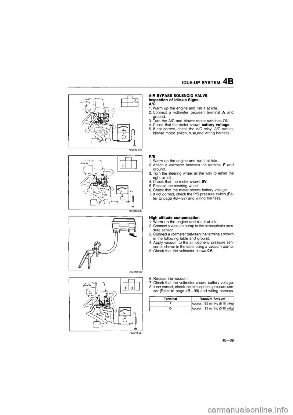
AIR BYPASS SOLENOID VALVE
Inspection of Idle-up Signal
A/C
1. Warm up the engine and run it at idle.
2. Connect a voltmeter between terminal A and
ground.
3. Turn the A/C and blower motor switches ON.
4. Check that the meter shows battery voltage.
5. If not correct, check the A/C relay, A/C switch,
blower motor switch, fuse,and wiring harness.
76G04B-048
P/S
1. Warm up the engine and run it at idle.
2. Attach a voltmeter between the terminal F and
ground.
3. Turn the steering wheel all the way to either the
right or left.
4. Check that the meter shows OV.
5. Release the steering wheel.
6. Check that the meter shows battery voltage.
7. If not correct, check the P/S pressure switch (Re-
fer to page 4B—92) and wiring harness.
76G04B-049
High altitude compensation
1. Warm up the engine and run it at idle.
2. Connect a vacuum pump to the atmospheric pres-
sure sensor.
3. Connect a voltmeter between the terminals shown
in the following table and ground.
4. Apply vacuum to the atmospheric pressure sen-
sor as shown in the table using a vacuum pump.
5. Check that the voltmeter shows OV.
76G04B-050
J
O
6. Release the vacuum.
7. Check that the voltmeter shows battery voltage.
8. If not correct, check the atmospheric pressure sen-
sor (Refer to page 4B—99) and wiring harness.
Terminal Vacuum Amount
F Approx. 155 mmHg (6.10 inHg)
D Approx.
85
mmHg (3.35 inHg)
76G04B-051
4B-39
Page 504 of 1865
4B FUEL SYSTEM
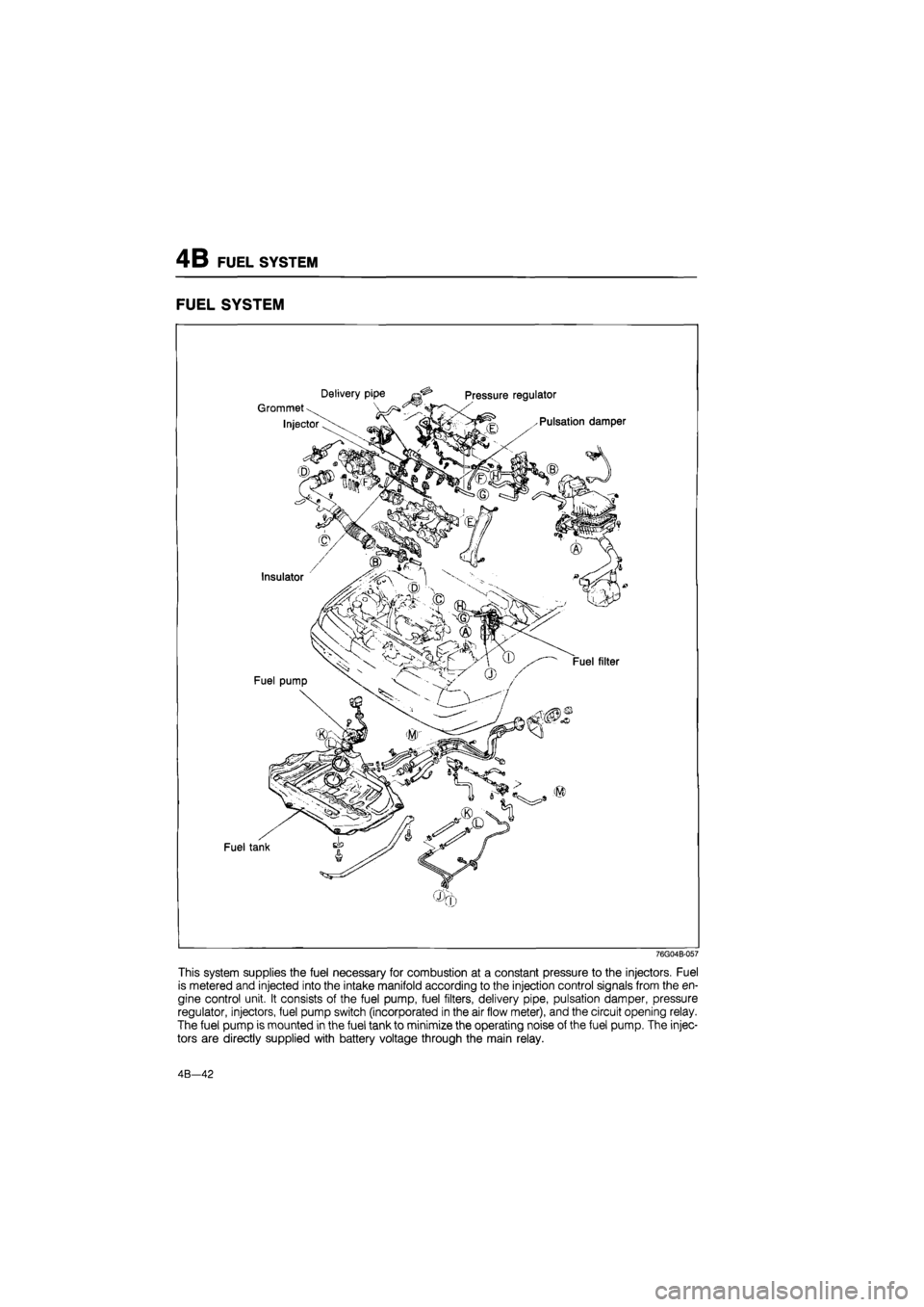
FUEL SYSTEM
76G04B-057
This system supplies the fuel necessary for combustion at a constant pressure to the injectors. Fuel
is metered and injected into the intake manifold according to the injection control signals from the en-
gine control unit. It consists of the fuel pump, fuel filters, delivery pipe, pulsation damper, pressure
regulator, injectors, fuel pump switch (incorporated in the air flow meter), and the circuit opening relay.
The fuel pump is mounted in the fuel tank to minimize the operating noise of the fuel pump. The injec-
tors are directly supplied with battery voltage through the main relay.
4B—42
Page 505 of 1865
FUEL SYSTEM 4B
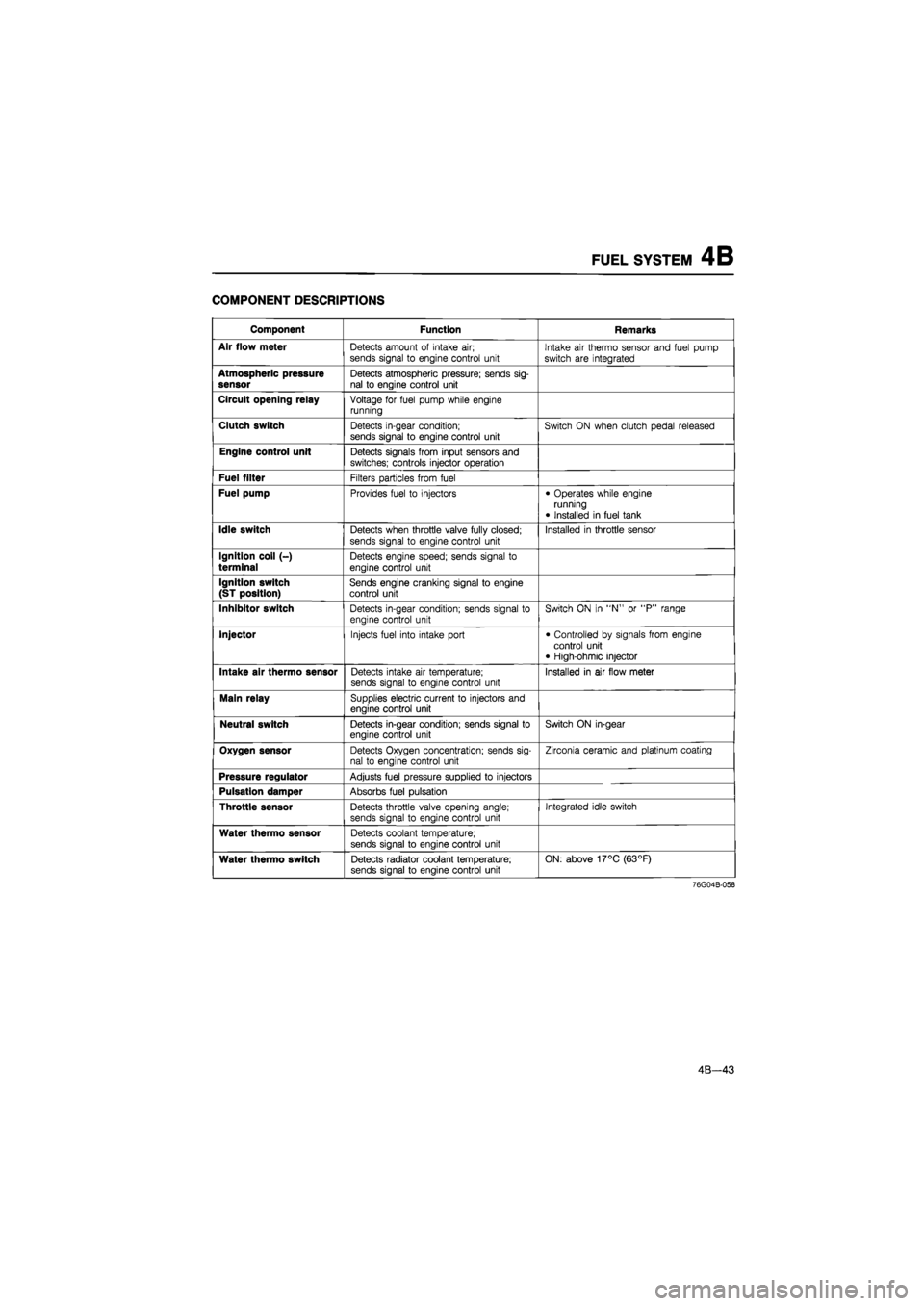
COMPONENT DESCRIPTIONS
Component Function Remarks
Air flow meter
Detects amount
of
intake
air;
sends signal
to
engine control unit Intake
air
thermo sensor and fuel pump
switch
are
integrated
Atmospheric pressure sensor
Detects atmospheric pressure; sends sig-nal
to
engine control unit
Circuit opening relay
Voltage
for
fuel pump while engine running
Clutch switch
Detects in-gear condition; sends signal
to
engine control unit Switch
ON
when clutch pedal released
Engine control unit
Detects signals from input sensors and switches; controls injector operation
Fuel filter
Filters particles from fuel
Fuel pump
Provides fuel
to
injectors • Operates while engine running
• Installed
in
fuel tank
Idle switch
Detects when throttle valve fully closed;
sends signal
to
engine control unit
Installed
in
throttle sensor
Ignition coil (-) terminal
Detects engine speed; sends signal
to
engine control unit
Ignition switch (ST position)
Sends engine cranking signal
to
engine control unit
Inhibitor switch
Detects in-gear condition; sends signal
to
engine control unit
Switch
ON in "N" or "P"
range
Injector
Injects fuel into intake port • Controlled
by
signals from engine control unit • High-ohmic injector
Intake air thermo sensor
Detects intake
air
temperature;
sends signal
to
engine control unit Installed
in air
flow meter
Main relay
Supplies electric current
to
injectors and engine control unit
Neutral switch
Detects in-gear condition; sends signal
to
engine control unit
Switch
ON
in-gear
Oxygen sensor
Detects Oxygen concentration; sends sig-nal
to
engine control unit
Zirconia ceramic and platinum coating
Pressure regulator
Adjusts fuel pressure supplied
to
injectors
Pulsation damper
Absorbs fuel pulsation
Throttle sensor
Detects throttle valve opening angle; sends signal
to
engine control unit
Integrated idle switch
Water thermo sensor
Detects coolant temperature;
sends signal
to
engine control unit
Water thermo switch
Detects radiator coolant temperature; sends signal
to
engine control unit ON: above 17°C (63°F)
76G04B-058
4B—43
Page 507 of 1865
FUEL SYSTEM 4B
86U04A-068
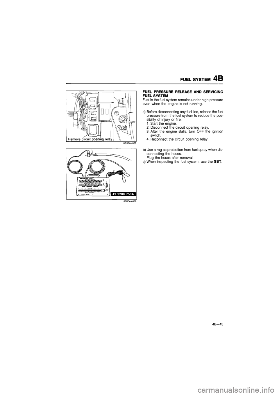
FUEL PRESSURE RELEASE AND SERVICING
FUEL SYSTEM
Fuel in the fuel system remains under high pressure
even when the engine is not running.
a) Before disconnecting any fuel line, release the fuel
pressure from the fuel system to reduce the pos-
sibility of injury or fire.
1. Start the engine.
2. Disconnect the circuit opening relay.
3. After the engine stalls, turn OFF the ignition
switch.
4. Reconnect the circuit opening relay.
b) Use a rag as protection from fuel spray when dis-
connecting the hoses.
Plug the hoses after removal.
c) When inspecting the fuel system, use the SST.
86U04A-069
4B—45
Page 511 of 1865
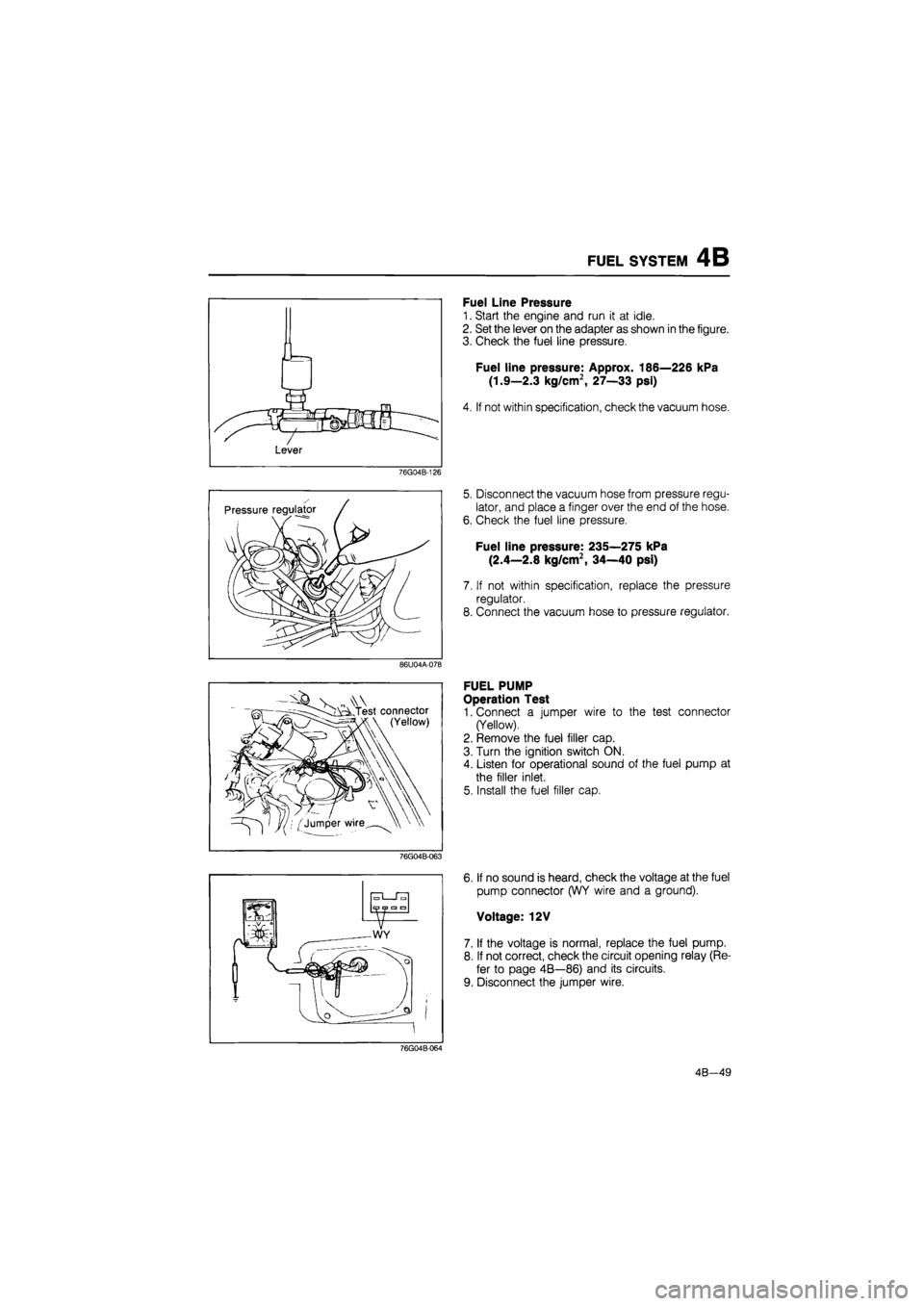
FUEL SYSTEM 4B
76G04B-126
86U04A-078
V^AN.
- Test connector
(Yellow)
76G04B-063
Fuel Line Pressure
1. Start the engine and run it at idle.
2. Set the lever on the adapter as shown in the figure.
3. Check the fuel line pressure.
Fuel line pressure: Approx. 186—226 kPa
(1.9—2.3 kg/cm2, 27—33 psi)
4. If not within specification, check the vacuum hose.
5. Disconnect the vacuum hose from pressure regu-
lator, and place a finger over the end of the hose.
6. Check the fuel line pressure.
Fuel line pressure: 235—275 kPa
(2.4—2.8 kg/cm2, 34—40 psi)
7. If not within specification, replace the pressure
regulator.
8. Connect the vacuum hose to pressure regulator.
FUEL PUMP
Operation Test
1. Connect a jumper wire to the test connector
(Yellow).
2. Remove the fuel filler cap.
3. Turn the ignition switch ON.
4. Listen for operational sound of the fuel pump at
the filler inlet.
5. Install the fuel filler cap.
6. If no sound is heard, check the voltage at the fuel
pump connector (WY wire and a ground).
Voltage: 12V
7. If the voltage is normal, replace the fuel pump.
8. If not correct, check the circuit opening relay (Re-
fer to page 4B—86) and its circuits.
9. Disconnect the jumper wire.
76G04B-064
4B—49