relay MAZDA 626 1987 Service Manual
[x] Cancel search | Manufacturer: MAZDA, Model Year: 1987, Model line: 626, Model: MAZDA 626 1987Pages: 1865, PDF Size: 94.35 MB
Page 654 of 1865

CONTROL SYSTEM 4C
Output Devices and In put Devices (Leaded fuel)
IGNITION SWITCH
(ON POSITION) X X X X X O X X X X O
TEST CONNECTOR X X X O X X X X X O X
KNOCK SENSOR X X X X X X X X X o X
ELECTRICAL LOAD
CONTROL UNIT X X X O X X X X X X X
P/S PRESSURE SWITCH X X X o X X X X X X X
A/C SWITCH X X X o X X X X O X X
IGNITION SWITCH (STA POSITION) O O X o O X O X X O X
NEUTRAL AND
CLUTCH SWITCH O X X o X X X X X X X
INTAKE AIR THERMO SENSOR X X X X X X O X X X X
WATER THERMO SENSOR O X X o X X O X X O o
IDLE SWITCH o X X o X X o X X O X
VARIABLE RESISTOR (IN AIR FLOW SENSOR) o X X X X X X X X X X
AIR FLOW SENSOR o X X X X X X X X O O
Ne SIGNAL o o X O o X O o X o O
G SIGNAL X O X X X X X X X X X
INPUT
DEVICE
OUTPUT
DEVICE
FUEL
INJECTION
AMOUNT
FUEL
INJECTION
TIMING
AIR
VALVE
ISC
VALVE
FUEL
PUMP
CONTROL
MAIN
POWER
CONTROL
SOLENOID
VALVE
(PRESSURE
REGULATOR
CONTROL)
SOLENOID
VALVE
(VARIABLE
INERTIA
CONTROL)
A/C
RELAY
IGNITER
AIR
FLOW
SENSOR
(BURN-OFF)
INPUT
DEVICE
OUTPUT
DEVICE
INJECTOR
BAC
VALVE
CONTROL
RELAY
SOLENOID
VALVE
(PRESSURE
REGULATOR
CONTROL)
SOLENOID
VALVE
(VARIABLE
INERTIA
CONTROL)
A/C
RELAY
IGNITER
AIR
FLOW
SENSOR
(BURN-OFF)
76G04C-168
4C—93
Page 655 of 1865

4C CONTROL SYSTEM
Output Devices
and
Engine Conditions (Unleaded fuel)
REMARK
*
Above
7,000
rpm:
fuel
cut
'Coolant
temp.:
below
50°C
(122°F)
41 Coolant
temp:
below
70°C
(158°F)
*2 Engine
speed
above
1,700
rpm
*3 Engine
speed:
1,500—3,500
rpm
*
During
hot
start
only
*
Engine
speed:
above
5,200
rpm
'Engine
speed:
above
3,000
rpm
'Delays
0.5
second
IGN:
ON
(ENGINE
NOT RUNNING)
No
injection
No bypass OFF
(main
fuel
pump
not
operated)
OFF
OFF
z
1
IDLE
(THROTTLE
VALVE
FULLY CLOSED)
Rich
and
i
lean
Sequential
(once
per
two
revolutions)
OFF
o en C3 UJ
z
"After
start-
ing:
ON
(Vacuum
cut) OFF
o
DECELE-
RATION
'Fuel
cut
L
Small
amount
of
bypass
air
N (1st
stage
operate:
o
o Ho 3 O CO CD > CO >
>; CO
CO c o
c o o
HEAVY
LOAD
•ST c
Closed
Small
amount
of
bypass
air
-co-CD CO
N (1st
stage
operate:
In CD 2? 03 a. o CD o> CO to "O c
*3 OFF (EGR)
o Ho 3 O CO CD > CO >
03 k-o CO c 03 CO z o *
CD c O) c 03 c o
c o o a 3
ACCELE-
RATION
Rich
o •*—• 3 o > CD
O
Small
amount
of
bypass
air
03 Q. O Q. E 3
ON
O
In CD 2? 03 a. o CD o> CO to "O c
ON
(EGR cut)
:F (Vacuum
to
pressure
regulatt
03 3 -C CO o
c 03 CS3 > X o o
z o * CO •o c CD Q. CD T3
C CO CD o "O 3= O c: 3 CO
LL LL o
MEDIUM
LOAD
WARM
Rich
and lean
|
Q. CD O
CD D
C CO E
CVJ.
z o fS *
*3 OFF (EGR)
:F (Vacuum
to
pressure
regulatt
E 3 3
c 03 i t 3 G, LL LL
T3 CD O c CO > "O <
C CO CD o "O 3= O c: 3 CO
LL LL o
MEDIUM
LOAD
COLD
ro
c CD 3 cr
z O "a CD a? CD CL o
F (2nd
stage
not
operated)
:F (Vacuum
to
pressure
regulatt
z o * O «
WARMING
UP
(DURING
IDLE)
Rich
CD CO c CD Q-O
o
c 3 CO O CO E CO
o c
stage
not
operated)
tr O UJ
z o
O
LL z
Fixed
at
BTDC
12°
CRANKING
(COLD
ENGINE)
1
group
(twice
per
revolution)
CO
«
CD urn i CO
CO
LL LL O
LL O * « o o
LL LL o
Fixed
at
BTDC
6°
z o
SOLENOID
VALVE
(PRESSURE
REGU-
LATOR
CONTROL)
CC
o z o o iii z
o z 111
OUTPUT
DEVICE
FUEL
INJECTION
AMOUNT FUEL
INJECTION
TIMING
AIR
VALVE
'
ISC
VALVE
FUEL
PUMP
CONTROL
MAIN
POWER
CONTROL
SOLENOID
VALVE
(No.1
PURGE)
SOLENOID
VALVE
(NO.2
PURGE)
SOLENOID
VALVE
(EGR)
SOLENOID
VALVE
(PRESSURE
REGU-
LATOR
CONTROL)
SOLENOID
VALVE
(VARIABLE
INE
TIA
CONTROL)
> <
Ul oc oc o
£T u. O 1 z oc 3 m
oc o
OUTPUT
DEVICE
INJECTOR
BAC
VALVE
CONTROL
RELAY
SOLENOID
VALVE
(No.1
PURGE)
SOLENOID
VALVE
(NO.2
PURGE)
SOLENOID
VALVE
(EGR)
SOLENOID
VALVE
(PRESSURE
REGU-
LATOR
CONTROL)
SOLENOID
VALVE
(VARIABLE
INE
TIA
CONTROL)
tn z Ul (0 z Ul o >-X o
A/C
RELAY
IGNITER
z Ul (O
=5 o
IL oc <
76G04C-169
4C—94
Page 656 of 1865
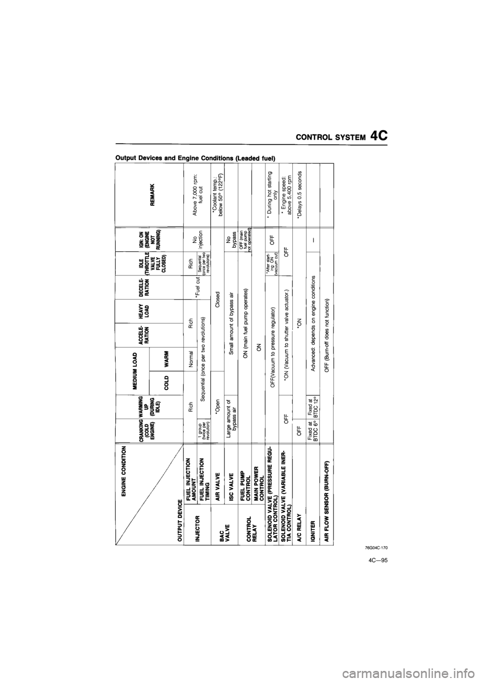
CONTROL SYSTEM
4C
Output Devices
and
Engine Conditions (Leaded fuel)
REMARK
E Q
O O O r-»" CD > o n <
fuel
cut
'Coolant
temp.:
below
50°
(122°F)
*
During
hot
starting
only
*
Engine
speed:
above
5,400
rpm
'Delays
0.5
seconds
IGN:
ON
(ENGINE
I
NOT
RUNNING)
o
z
injection
No
bypass
OFF
(main
fuel
pump
not
operated)
OFF
LL
I
IDLE
(THROTTLE
VALVE
FULLY
CLOSED)
Rich
I
Sequential (once
per
two
revolutions)
"After
start-
ing:
ON
(vacuum
cut)
O
DECELE-
RATION
i
i
'Fuel
cut
•o CD CO "co" CD ts o to 3 o CO CD > CO
CO c o
c o o
HEAVY
LOAD
sz "co" c
O o CO CO CO Q. >. -O
O
CD Q. O CL E CL ® D
C CO F
o 08 3 u> £ CD 3 CO 0) CD
o to 3 o CO CD > CO
z
B
ACCELE-RATION
ir o 3 0 > CD 1 O
C
O E CO
"CO
CD Q. O CL E CL ® D
C CO F
z
o 08 3 u> £ CD 3 CO 0) CD
CD e 3 SZ CO o
O * CO
c CD CL CD T3
c CO 8 "D
'
MEDIUM
LOAD
WARM
Normal
CD Q. CD O
E CO
z
O
o o_ O
E
3 3
o CO ^ LL LL O
E 3 3 O CO
•o
c
3
m
LL LL o
'
MEDIUM
LOAD
COLD
.H C CD 3 CT
o_ O
E
3 3
o CO ^ LL LL O
z
o *
WARMING
UP
(DURING
IDLE)
Rich
CD CO
*Open
B
3
CO
O
CO
E
<®
LL
Fixed
at
BTDC
12°
CRANKING
(COLD
ENGINE)
1
group
(twice
per
revolution)
CO
«
0)
>,
u>n w-CO
o
OFF
Fixed
at
BTDC
6°
ENGINE
CONDITION
OUTPUT
DEVICE
FUEL
INJECTION
AMOUNT
'
FUEL
INJECTION
TIMING
AIR
VALVE
ISC
VALVE
FUEL
PUMP
CONTROL MAIN
POWER
CONTROL
SOLENOID
VALVE
(PRESSURE
REGU-
LATOR
CONTROL)
SOLENOID
VALVE
(VARIABLE
INER-
TIA
CONTROL)
(T ik 0 1 z DC 3
ffl
OC o tn
OUTPUT
DEVICE
INJECTOR
BAC
VALVE
CONTROL
RELAY
SOLENOID
VALVE
(PRESSURE
REGU-
LATOR
CONTROL)
SOLENOID
VALVE
(VARIABLE
INER-
TIA
CONTROL)
A/C
RELAY
IGNITER
Z Ul tn
£ o
ik DC <
76G04C-170
4C—95
Page 657 of 1865

4C CONTROL SYSTEM
EGI MAIN FUSE
Inspection
Check the continuity of EGI main fuse.
69G04A-161
CONTROL RELAY
Power Supply Circuit
1. Check that a "clicking" sound is heard at the con-
trol relay when turning the ignition switch ON and
OFF.
Note
The control relay is located under the center
console.
76G04C-171
2. Apply 12V to the 2B terminal and ground the 2D
terminal of the control relay.
3. Check voltage at the terminals with an voltmeter.
terminal
Terminals Grounded Not grounded
2C 12V OV
2E 12V OV
76G04C-172
From EGI From '9' From Ig. main fuse switch (ON) / switch
(ST)
To C/U / 9round To main To injector fuel Pump
Fuel Pump Circuit
1. Apply 12V and a ground to the terminals described
below and check the terminals with an ohmmeter
or voltmeter.
Terminal applied 12V
Terminal
grounded
Terminal checked
Correct condition
1B 1D 2F-1A Continuity
2F 1C 1A ADDrox.12V
76G04C-173
4C-96
Page 660 of 1865

CONTROL SYSTEM 4C
Terminal Voltage
If the input and output devices wiring are normal, but the engine control unit terminal voltage is incor-
rect, replace the engine control unit.
Terminal Input Output Connection to Voltage (After warming-up) Remark Terminal Input Output Connection to Ign: ON Idle Remark
1A — — — — — —
1B o Self-Diagnosis Checker (Code No.)
For 3sec. after ignition switch OFF ->• ON: below 2.5V (Buzzer sounds) After 3sec.: approx. 12V (Buzzer does not sound)
• Using Self-Diagnosis Check-er and test con-nector grounded • Buzzer sounds: below 2.5V • Buzzer does not sound: approx. 12V
1C o
Solenoid valve (Variable inertia control) Approx. 12V
Above 5200 rpm (Unleaded fuel) or 5400 rpm (Leaded fuel): Below 2.5V
1D o Self-Diagnosis Checker (Monitor lamp)
For 3sec.after igni-tion switch OFF -» ON:
approx. 5V (light il-luminates)
After 3sec.: approx. 12V (light does not illuminate)
(Test connector grounded) approx. 5V (Test connector not grounded) Monitor lamp ON: approx. 5V Monitor lamp OFF: approx. 12V
With Self-Diagnosis
Checker
1E O Idle switch Accelerator pedal released: OV
Accelerator pedal depressed: approx. 12V
1F o A/C relay A/C switch ON: below 2.5V
A/C switch OFF: approx. 12V Blower motor ON
1G O Neutral or clutch switch
In-gear condition Clutch pedal depressed: approx. 12V Clutch pedal released: OV
MTX (Neutral: con-stant approx. 12V)
1H
(U/F) o Water thermo
switch
Approx. 12V Radiator temp.: be-low 17°C (63°R 1H
(U/F) o Water thermo
switch OV Radiator temp.:
above 17°C (63°F)
11 o Electrical load control unit E/L switch ON: below 2.5V
E/L switch OFF: approx. 10—12V
Electrical load: Rear defroster switch
Headlight switch Blower motor switch (3rd & 4th position) Electrical fan switch
1J — — — — —
1K o P/S pressure
switch
Constant approx.
12V
P/S ON: below 2.5V P/S OFF: approx. 12V
1L o A/C switch A/C switch ON: below 2.5V A/C switch OFF: aDDrox. 12V Blower motor: ON
1M o Distributor
(Ne signal) OV or 5V Approx. 2.0V
1N o Distributor (G signal) OV or 5V Approx. 1.2V
Note
Terminals labeled "U/F" are only for unleaded fuel.
4C-99
Page 661 of 1865
4C CONTROL SYSTEM
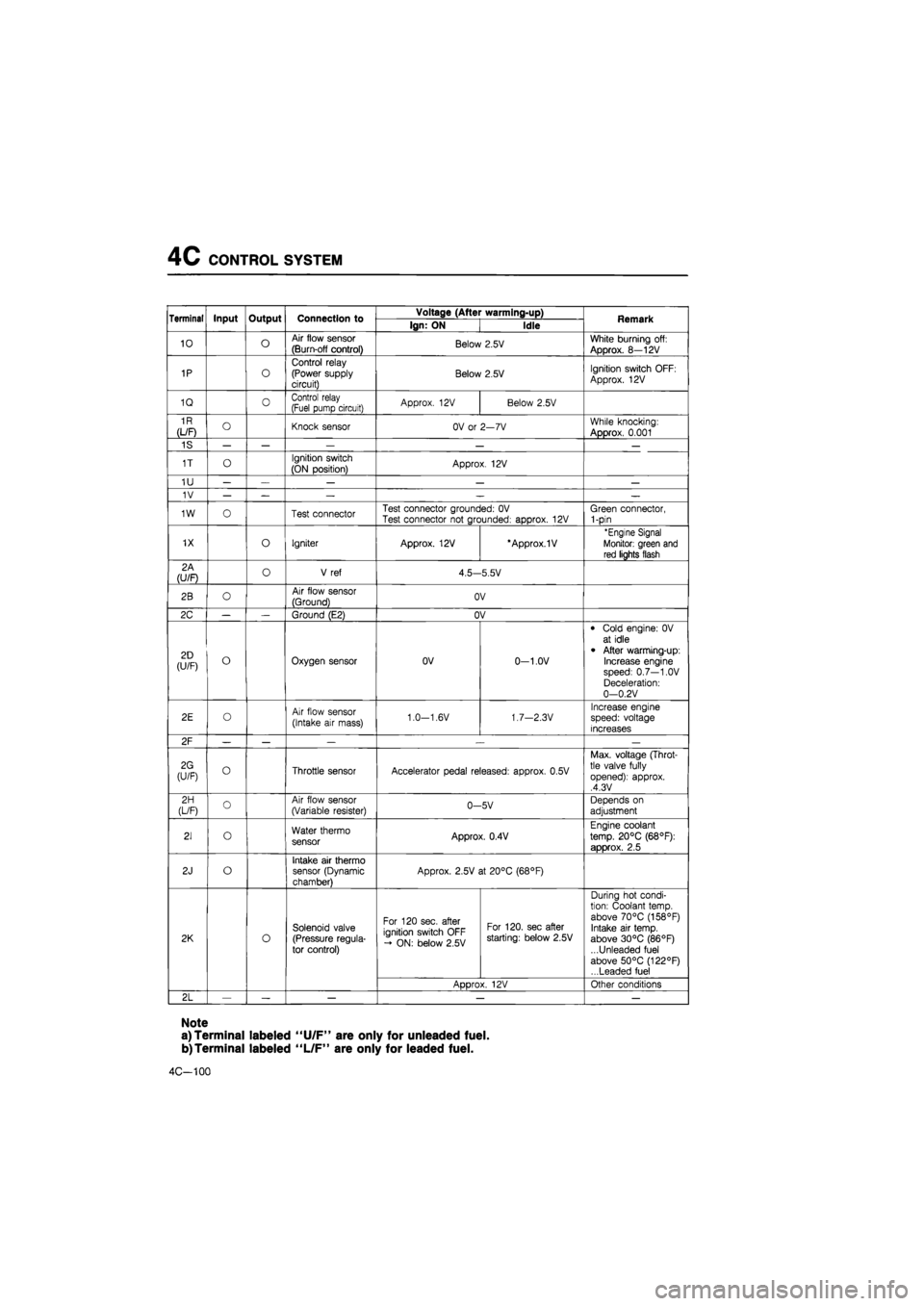
Terminal Input Output Connection to Voltage (After warming-up) Remark Terminal Input Output Connection to Ign: ON Idle Remark
10 o Air flow sensor
(Burn-off control) Below 2.5V White burning off:
Approx. 8—12V
1P o
Control relay (Power supply circuit) Below 2.5V Ignition switch OFF:
Approx. 12V
1Q 0 Control relay (Fuel pump circuit) Approx. 12V Below 2.5V
1R
(L/F) O Knock sensor OV or 2—7V While knocking:
Approx. 0.001
1S — — — — —
1T o Ignition switch
(ON position) Approx. 12V
1U — — — — —
1V — — — — —
1W o Test connector Test connector grounded: OV Test connector not grounded: approx. 12V Green connector, 1-pin
1X o Igniter Approx. 12V *Approx.1V 'Engine Signal
Monitor: green and
red lights flash
2A (U/F) o V ref 4.5—5.5V
2B o Air flow sensor
(Ground) OV
2C — — Ground (E2) OV
2D (U/F) o Oxygen sensor OV 0-1.0V
• Cold engine: 0V at idle
• After warming-up: Increase engine speed: 0.7—1.0V Deceleration: 0—0.2V
2E o Air flow sensor
(Intake air mass) 1.0—1.6V 1.7—2.3V Increase engine speed: voltage increases
2F — — — .— —
2G (U/F) o Throttle sensor Accelerator pedal released: approx. 0.5V
Max. voltage (Throt-tle valve fully opened): approx. ,4.3V
2H (L/F) o Air flow sensor (Variable resister) 0-5V Depends on
adjustment
21 o Water thermo sensor Approx. 0.4V
Engine coolant
temp. 20°C (68°F):
approx. 2.5
2J o Intake air thermo sensor (Dynamic chamber)
Approx. 2.5V at 20°C (68°F)
2K o
Solenoid valve (Pressure regula-tor control)
For 120 sec. after ignition switch OFF - ON: below 2.5V
For 120. sec after starting: below 2.5V
During hot condi-tion: Coolant temp, above 70°C (158°F) Intake air temp, above 30°C (86°F) ...Unleaded fuel above 50°C (122°F) ...Leaded fuel
2K o
Solenoid valve (Pressure regula-tor control)
ADDrox. 12V Other conditions
2L — — — — —
Note
a) Terminal labeled "U/F" are only for unleaded fuel.
b)Terminal labeled "L/F" are only for leaded fuel.
4C-100
Page 663 of 1865
4C CONTROL SYSTEM
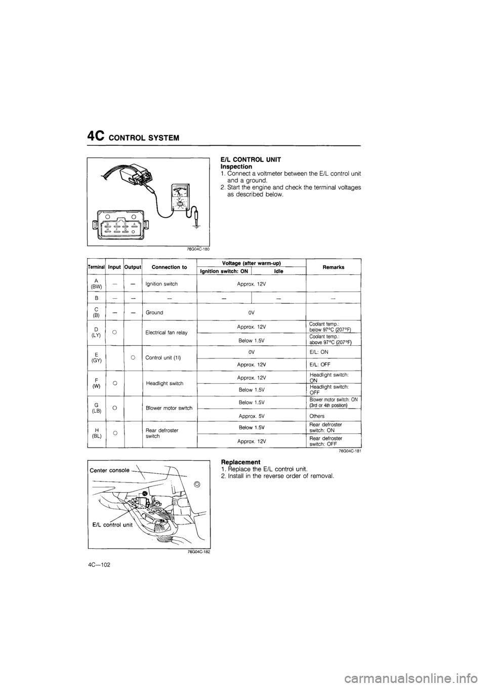
E/L CONTROL UNIT
Inspection
1. Connect a voltmeter between the E/L control unit
and a ground.
2. Start the engine and check the terminal voltages
as described below.
76G04C-180
Terminal Input Output Connection to Voltage (after warm-up) Remarks Terminal Input Output Connection to Ignition switch: ON Idle Remarks
A
(BW) — — Ignition switch Approx. 12V
B — — — — — —
C
(B) — — Ground OV
D (LY) O Electrical fan relay Approx. 12V Coolant temp.: below 97°C (207°F) D (LY) O Electrical fan relay
Below 1,5V Coolant temp.:
above 97°C (207°F)
E (GY) Control unit (11) OV E/L: ON E (GY) Control unit (11)
Approx. 12V E/L: OFF
F (W) O Headlight switch Approx. 12V Headlight switch:
ON F (W) O Headlight switch
Below 1,5V Headlight switch:
OFF
G (LB) o Blower motor switch Below 1.5V Blower motor switch: ON (3rd or 4th position) G (LB) o Blower motor switch
Approx. 5V Others
H
(BL) o Rear defroster
switch
Below 1.5 V Rear defroster
switch: ON H
(BL) o Rear defroster
switch Approx. 12V Rear defroster switch: OFF
76G04C-181
Replacement
1. Replace the E/L control unit.
2. Install in the reverse order of removal.
76G04C-182
4C—102
Page 707 of 1865

5
ENGINE ELECTRICAL SYSTEM
OUTLINE 5— 2
STRUCTURAL VIEW 5— 2
SPECIFICATIONS 5— 5
TROUBLESHOOTING 5— 7
BATTERY 5— 8
INSPECTION 5— 8
RECHARGE. 5— 8
SPARK PLUG 5— 9
REMOVAL AND INSTALLATION 5— 9
INSPECTION 5— 9
IGNITION COIL 5—10
INSPECTION 5—10
HIGH-TENSION LEAD 5—10
INSPECTION 5—10
DISTRIBUTOR 5—11
SPARK TEST 5—11
IGNITION TIMING 5—11
SPARK CONTROL 5—12
REMOVAL 5—14
DISASSEMBLY 5—15
INSPECTION 5—16
ASSEMBLY 5—17
INSTALLATION 5—18
H.E.I. TROUBLESHOOTING 5—19
IGNITER (FE DOHC) 5—20
INSPECTION 5—20
ALTERNATOR 5—21
CROSS SECTIONAL VIEW 5—21
CHARGING SYSTEM 5—22
TROUBLESHOOTING 5—23
REMOVAL 5—27
DISASSEMBLY 5—28
INSPECTION 5—32
ASSEMBLY 5—35
INSTALLATION 5—36
V-BELT TENSION 5—37
STARTER (GASOLINE ENGINE
0.85, 0.95 KW TYPE) 5—38
STARTING SYSTEM CIRCUIT 5—38
ON-VEHICLE INSPECTION 5—38
REMOVAL AND INSTALLATION 5—39
DISASSEMBLY AND ASSEMBLY 5—39
INSPECTION 5—40
PERFORMANCE INSPECTION 5—43
STARTER
(GASOLINE ENGINE, 1.4 KW TYPE) 5—45
STARTING SYSTEM 5—45
ON-VEHICLE UNSPECTION 5—45
REMOVAL 5—46
DISASSEMBLY 5—46
INSPECTION 5—49
ASSEMBLY 5—53
CHECKING OPERATION 5—54
INSTALLATION 5—55
STARTER
(DIESEL ENGINE, 2.0 kW TYPE) .... 5—56
STARTING SYSTEM CIRCUIT 5—56
ON-VEHICLE INSPECTION 5—56
REMOVAL AND INSTALLATION 5—57
DISASSEMBLY AND ASSEMBLY 5—57
INSPECTION 5—61
PERFORMANCE INSPECTION 5—64
STARTER
(DIESEL ENGINE, 2.2 kW TYPE).... 5—66
STARTING SYSTEM CIRCUIT 5—66
ON-VEHICLE INSPECTION 5—66
REMOVAL AND INSTALLATION 5—67
DISASSEMBLY AND ASSEMBLY 5—67
INSPECTION 5—71
PERFORMANCE INSPECTION 5—74
QUICK START SYSTEM (QSS) 5-76
COMPONENT LOCATION 5—76
CIRCUIT DIAGRAM 5—76
SYSTEM OPERATION 5—77
TROUBLESHOOTING GUIDE 5—78
CONTROL UNIT 5—79
GLOW PLUG RELAY 5—80
BLOW PLUG 5—80
WATER TEMPERATURE SWITCH.... 5—80
76g05x-001
Page 784 of 1865
QUICK START SYSTEM (QSS) 5
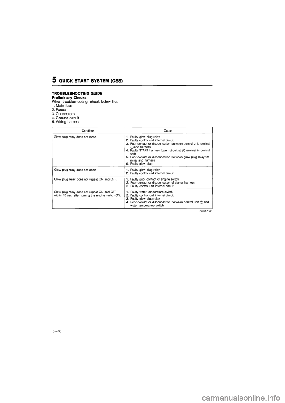
TROUBLESHOOTING GUIDE
Preliminary Checks
When troubleshooting, check below first.
1. Main fuse
2. Fuses
3. Connectors
4. Ground circuit
5. Wiring harness
Condition Cause
Glow plug relay does not close. 1. Faulty glow plug relay 2. Faulty control unit internal circuit
3. Poor contact or disconnection between control unit terminal ©and harness
4. Faulty START harness (open circuit at ©terminal in control unit) 5. Poor contact or disconnection between glow plug relay ter-minal and harness 6. Faulty glow plug
Glow plug relay does not open 1. Faulty glow plug relay 2. Faulty control unit internal circuit
Glow plug relay does not repeat ON and OFF. 1. Faulty poor contact of engine switch 2. Poor contact or disconnection of starter harness 3. Faulty control unit internal circuit
Glow plug relay does not repeat ON and OFF within 15 sec. after turning the engine switch ON. 1. Faulty water temperature switch 2. Faulty control unit internal circuit
3. Faulty glow plug relay
4. Poor contact or disconnection between control unit © and water temperature switch
76G05X-051
5-78
Page 785 of 1865
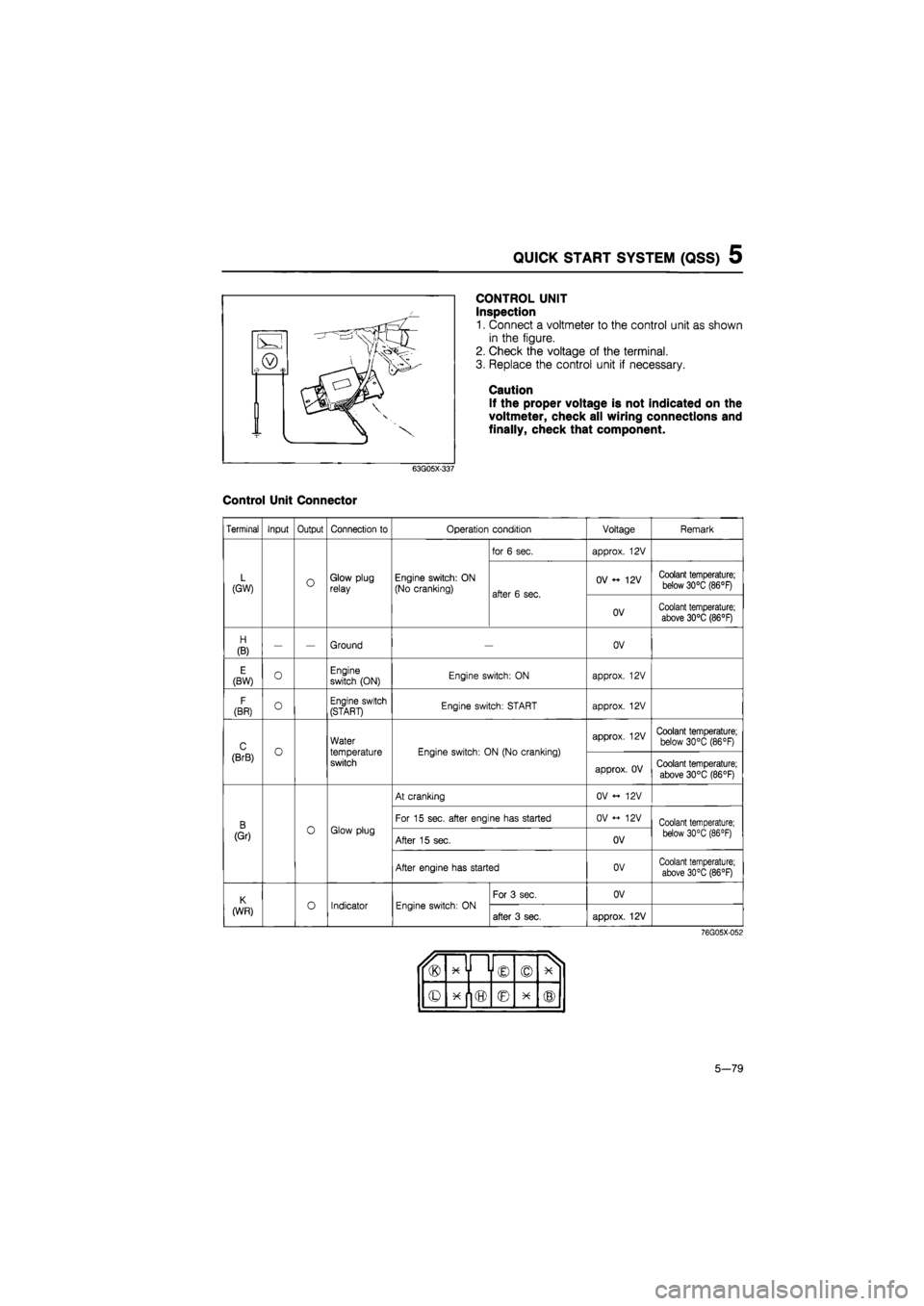
QUICK START SYSTEM (QSS) 5
CONTROL UNIT
Inspection
1. Connect a voltmeter to the control unit as shown
in the figure.
2. Check the voltage of the terminal.
3. Replace the control unit if necessary.
Caution
If the proper voltage is not indicated on the
voltmeter, check all wiring connections and
finally, check that component.
63G05X-337
Control Unit Connector
Terminal Input Output Connection to Operation condition Voltage Remark
for 6 sec. approx. 12V
L (GW) O Glow plug relay Engine switch: ON (No cranking) after 6 sec.
OV 12V Coolant temperature; below 30°C (86°F) after 6 sec.
OV Coolant temperature; above 30°C (86°F)
H
(B) — — Ground OV
E (BW) 0 Engine switch (ON) Engine switch: ON approx. 12V
F
(BR) O Engine switch (START) Engine switch: START approx. 12V
C o
Water
temperature switch
Engine switch: ON (No cranking)
approx. 12V Coolant temperature; below 30°C (86°F)
(BrB) o
Water
temperature switch
Engine switch: ON (No cranking)
approx. OV Coolant temperature;
above 30°C (86°F)
At cranking OV <- 12V
B 0 Glow plug
For 15 sec. after engine has started OV <-> 12V Coolant temperature;
(Gr) 0 Glow plug After 15 sec. OV below 30°C (86 °F)
After engine has started OV Coolant temperature; above 30°C (86°F)
K o Indicator Engine switch: ON
For 3 sec. OV
(WR) o Indicator Engine switch: ON after 3 sec. approx. 12V
76G05X-052
u® x y i © © X 1
© © X ®
5-79