differential MAZDA 626 1987 Service Manual
[x] Cancel search | Manufacturer: MAZDA, Model Year: 1987, Model line: 626, Model: MAZDA 626 1987Pages: 1865, PDF Size: 94.35 MB
Page 1115 of 1865
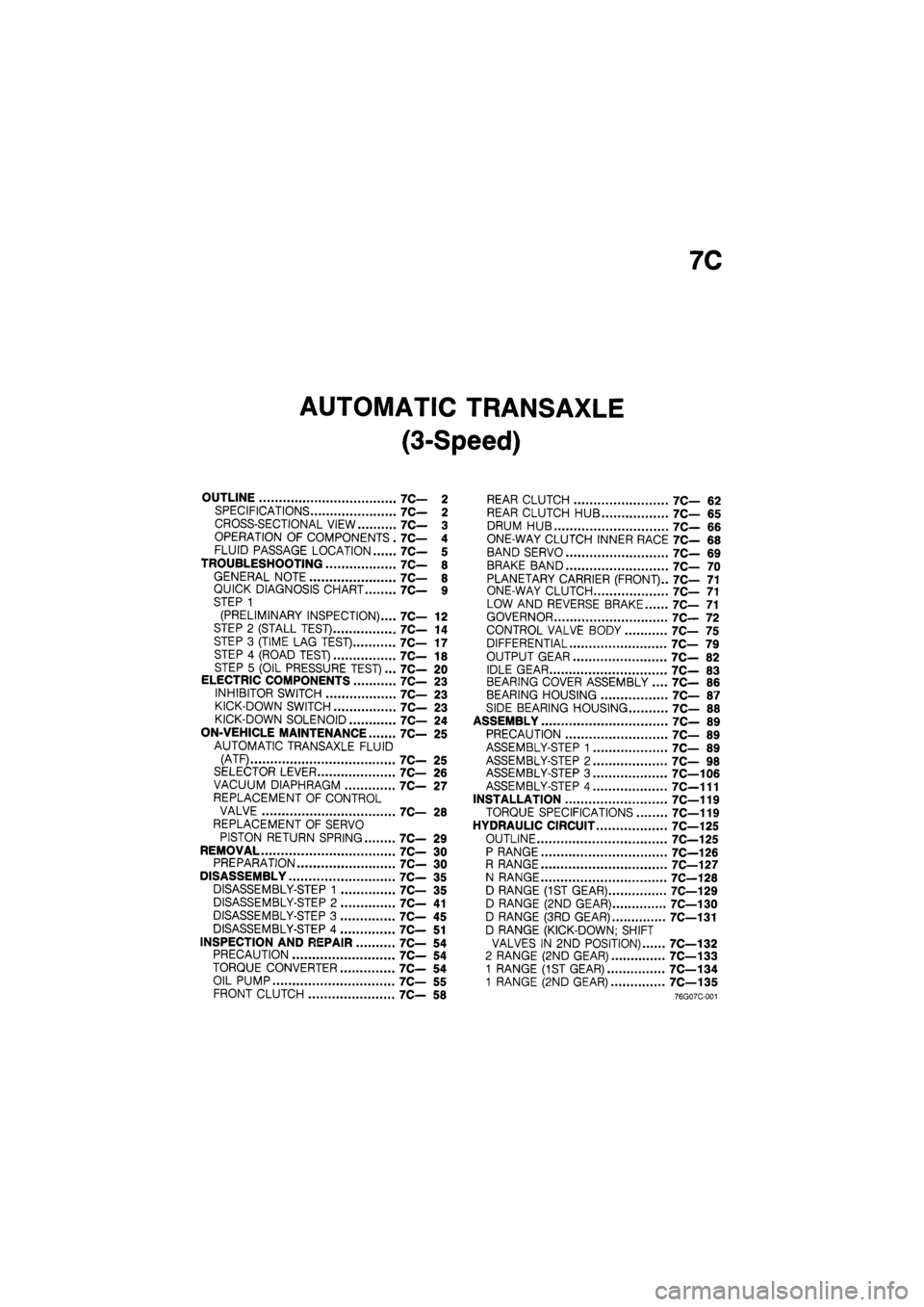
7C
AUTOMATIC TRANSAXLE
(3-Speed)
OUTLINE 7C— 2
SPECIFICATIONS 7C— 2
CROSS-SECTIONAL VIEW 7C— 3
OPERATION OF COMPONENTS . 7C— 4
FLUID PASSAGE LOCATION 7C— 5
TROUBLESHOOTING 7C— 8
GENERAL NOTE 7C— 8
QUICK DIAGNOSIS CHART 7C— 9
STEP 1
(PRELIMINARY INSPECTION).... 7C— 12
STEP 2 (STALL TEST) 7C— 14
STEP 3 (TIME LAG TEST) 7C— 17
STEP 4 (ROAD TEST) 7C— 18
STEP 5 (OIL PRESSURE TEST)... 7C— 20
ELECTRIC COMPONENTS 7C— 23
INHIBITOR SWITCH 7C— 23
KICK-DOWN SWITCH 7C— 23
KICK-DOWN SOLENOID 7C— 24
ON-VEHICLE MAINTENANCE 7C- 25
AUTOMATIC TRANSAXLE FLUID
(ATF) 7C— 25
SELECTOR LEVER 7C— 26
VACUUM DIAPHRAGM 7C— 27
REPLACEMENT OF CONTROL
VALVE 7C— 28
REPLACEMENT OF SERVO
PISTON RETURN SPRING 7C— 29
REMOVAL 7C— 30
PREPARATION 7C— 30
DISASSEMBLY 7C— 35
DISASSEMBLY-STEP 1 7C— 35
DISASSEMBLY-STEP 2 7C— 41
DISASSEMBLY-STEP 3 7C— 45
DISASSEMBLY-STEP 4 7C— 51
INSPECTION AND REPAIR 7C- 54
PRECAUTION 7C— 54
TORQUE CONVERTER 7C— 54
OIL PUMP 7C— 55
FRONT CLUTCH 7C— 58
REAR CLUTCH 7C— 62
REAR CLUTCH HUB 7C— 65
DRUM HUB 7C— 66
ONE-WAY CLUTCH INNER RACE 7C— 68
BAND SERVO 7C— 69
BRAKE BAND 7C— 70
PLANETARY CARRIER (FRONT).. 7C— 71
ONE-WAY CLUTCH 7C— 71
LOW AND REVERSE BRAKE 7C— 71
GOVERNOR 7C— 72
CONTROL VALVE BODY 7C— 75
DIFFERENTIAL 7C— 79
OUTPUT GEAR 7C— 82
IDLE GEAR 7C— 83
BEARING COVER ASSEMBLY .... 7C— 86
BEARING HOUSING 7C— 87
SIDE BEARING HOUSING 7C— 88
ASSEMBLY 7C— 89
PRECAUTION 7C— 89
ASSEMBLY-STEP 1 7C— 89
ASSEMBLY-STEP 2 7C— 98
ASSEMBLY-STEP 3 7C—106
ASSEMBLY-STEP 4 7C—111
INSTALLATION 7C—119
TORQUE SPECIFICATIONS 7C—119
HYDRAULIC CIRCUIT 7C—125
OUTLINE 7C—125
P RANGE 7C—126
R RANGE 7C—127
N RANGE 7C—128
D RANGE (1ST GEAR) 7C—129
D RANGE (2ND GEAR) 7C—130
D RANGE (3RD GEAR) 7C—131
D RANGE (KICK-DOWN; SHIFT
VALVES IN 2ND POSITION) 7C—132
2 RANGE (2ND GEAR) 7C—133
1 RANGE (1ST GEAR) 7C—134
1 RANGE (2ND GEAR) 7C—135
76G07C-001
Page 1117 of 1865
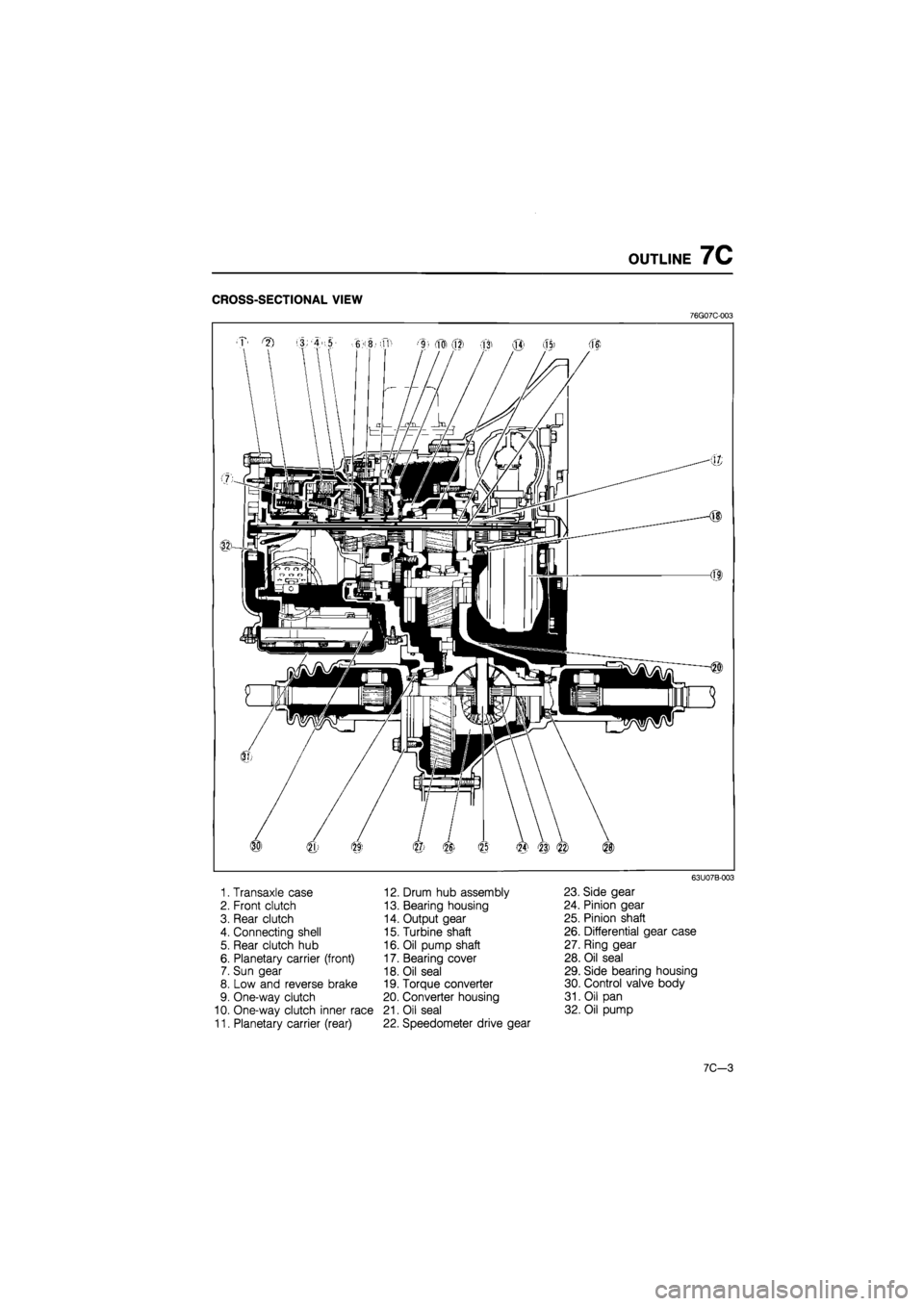
OUTLINE 7C
CROSS-SECTIONAL VIEW
76G07C-003
1. Transaxle case
2. Front clutch
3. Rear clutch
4. Connecting shell
5. Rear clutch hub
6. Planetary carrier (front)
7. Sun gear
8. Low and reverse brake
9. One-way clutch
10. One-way clutch inner race
11. Planetary carrier (rear)
12. Drum hub assembly
13. Bearing housing
14. Output gear
15. Turbine shaft
16. Oil pump shaft
17. Bearing cover
18. Oil seal
19. Torque converter
20. Converter housing
21. Oil seal
22. Speedometer drive gear
63U07B-003
23. Side gear
24. Pinion gear
25. Pinion shaft
26. Differential gear case
27. Ring gear
28. Oil seal
29. Side bearing housing
30. Control valve body
31. Oil pan
32. Oil pump
7C-3
Page 1125 of 1865
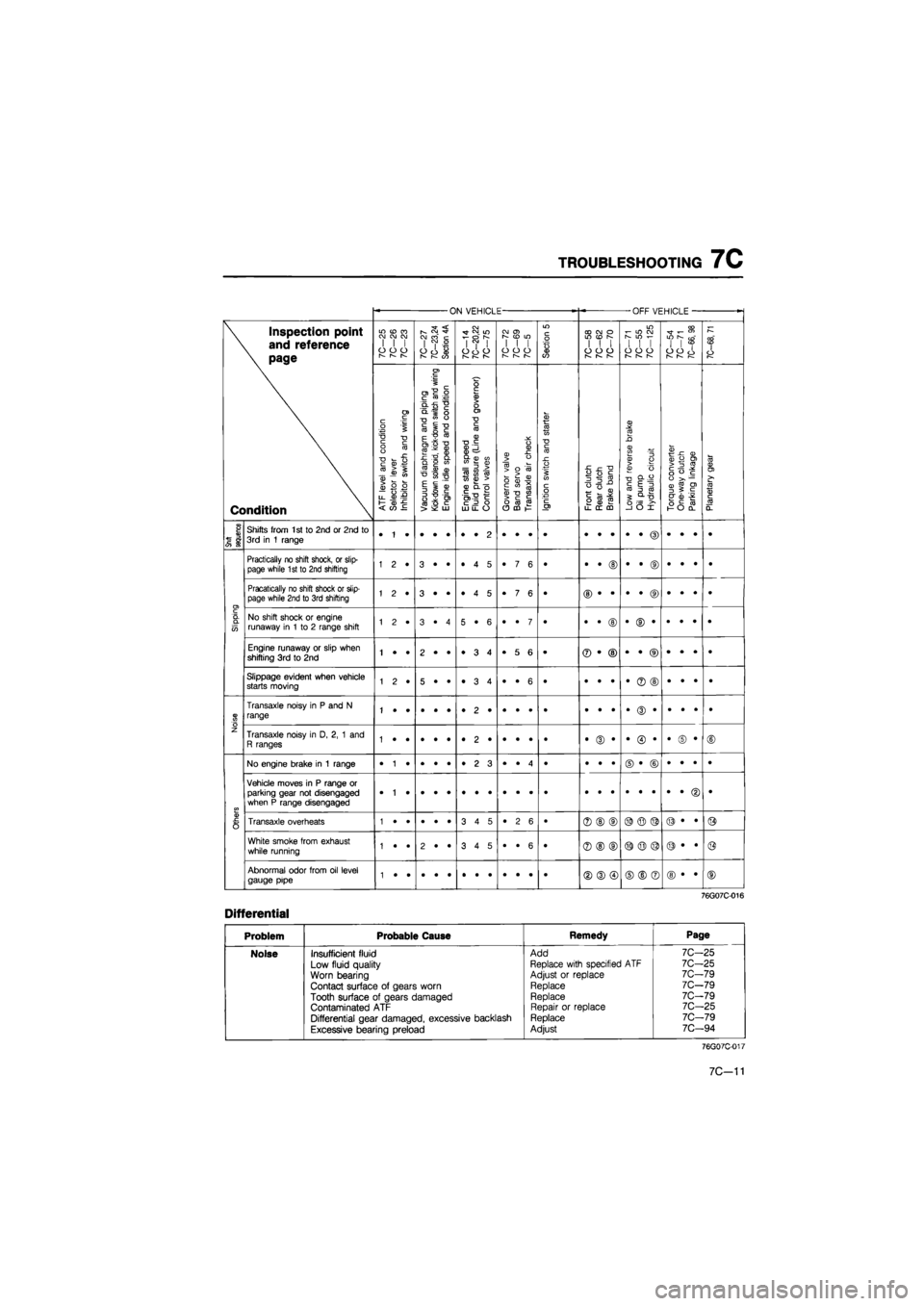
TROUBLESHOOTING
7C
ON VEHICLE -OFF VEHICLE
-
\ Inspection point
\
and
reference
\ page
Condition
in cd
ra
CM CM CM
I
I I
o
o o
I—
r~—
r—
7C—27
7C—23,24
Section
4A
7C—14
7C—20,22
7C-75
CM
0>
[—
CO
LO I
I I
O
O O
r^ r—
Section
5
CD CM
O
in (D
s
I
I I
o
o o
r—
r^
w
CM
r-
m f-
I
I I
o
o o
r-— I—
r-—
7C—54
7C-71
7C—66,
98
7C-68,
71 \ Inspection point
\
and
reference
\ page
Condition
ATR
level
and
condition
Selector
lever
Inhibitor
switch
and
wiring
Vacuum
diaphragm
and
piping
Kick-down
solenoid,
kick-down
switch
and
wiring
Engine
idle
speed
and
condition
Engine
stall
speed
Fluid
pressure
(Line
and
governor)
Control
valves
Governor
valve
Band
servo
Transaxle
air
check
Ignition
switch
and
starter
Front
clutch
Rear
clutch
Brake
band
Low
and
reverse
brake
Oil
pump
Hydraulic
circuit
Torque
converter
One-way
clutch
Parking
linkage
Planetary
gear
Snift
sequence
Shifts from
1st to
2nd
or
2nd
to
3rd
in 1
range
Slipping
Practically
no
shift shock,
or
slip-page while 1st
to
2nd shifting 1
2 •
3
• •
•
4 5
•
7 6
• •
• ©
•
• ©
•
• •
•
Slipping
Pracatically
no
shift shock
or
slip-page while 2nd
to
3rd shifting 1
2 •
3
• •
•
4 5
•
7 6
•
Slipping
No shift shock
or
engine runaway
in 1 to 2
range shift 1
2 •
3
• 4
5
• 6
•
• 7
• •
• ©
•
© •
•
• •
•
Slipping
Engine runaway
or
slip when shifting
3rd to 2nd
1
• •
2
• •
•
3 4
•
5 6
• ®
• ©
•
• ®
•
• •
•
Slipping
Slippage evident when vehicle starts moving 1
2 •
5
• •
•
3 4
•
• 6
• •
• •
•
® ©
•
• •
•
Noise
Transaxle noisy
in P and N
range
Noise
Transaxle noisy
in D, 2, 1 and
R ranges •
(D •
•
© •
•
© •
©
Others
No engine brake
in 1
range •
1 •
•
• •
•
2 3
•
• 4
• •
• •
©
• ©
•
• •
•
Others
Vehicle moves
in P
range
or
parking gear
not
disengaged when
P
range disengaged
•
Others
Transaxle overheats 3
4 5
•
2 6
• ®
©
(D ©
© ©
©
• •
©
Others
White smoke from exhaust while running 1
• •
2
• •
3
4 5
•
• 6
• ®
© ©
©
© ©
©
• •
@
Others
Abnormal odor from
oil
level gauge pipe ©
® ©
©
© ®
©
• •
©
76G07C-016
Differential
Problem Probable Cause Remedy Page
Noise Insufficient fluid Add 7C—25
Low fluid quality Replace with specified
ATF
7C-25
Worn bearing Adjust
or
replace 7C-79
Contact surface
of
gears worn Replace 7C-79
Tooth surface
of
gears damaged Replace 7C-79
Contaminated
ATF
Repair
or
replace 7C-25
Differential gear damaged, excessive backlash Replace 7C-79
Excessive bearing preload Adjust 7C—94
76G07C-017
7C—11
Page 1146 of 1865

7C REMOVAL
14. Disconnect the tie-rod ends with the SST.
76G07C-061
76G07C-062
76G07C-063
15. Remove the stabilizer bar control links.
16. Remove the bolts and nuts at the left and right low-
er arm ball joints.
17. Pull the lower arms downward to separate them
from the knuckles.
Caution
Do not damage the ball joint dust boots.
18. Separate the left driveshaft from the transaxle by
prying with a bar inserted between the shaft and
the case.
Caution
Do not damage the oil seal.
19. Remove the joint shaft bracket.
20. Separate the right driveshaft together with the joint
shaft in the same manner.
21. Install the SST into the differential side gears.
Caution
Failure to install the SST may allow the
differential side gears to become misaligned.
76G07C-064
7C—32
Page 1151 of 1865
DISASSEMBLY 7C
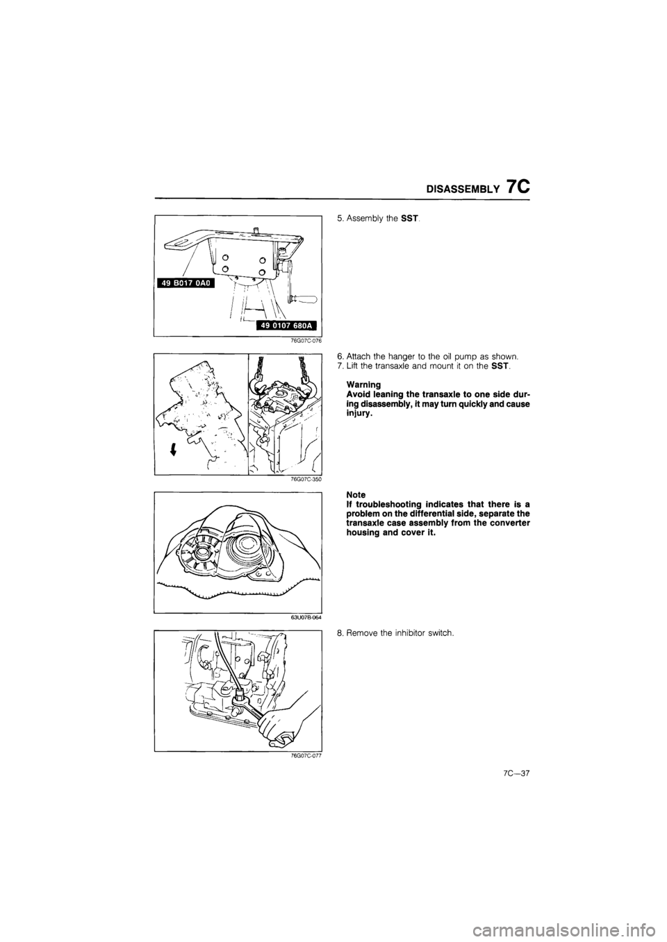
5. Assembly the SST.
76G07C-076
76G07C-350
6. Attach the hanger to the oil pump as shown.
7. Lift the transaxle and mount it on the SST.
Warning
Avoid leaning the transaxle to one side dur-
ing disassembly, it may turn quickly and cause
injury.
Note
If troubleshooting indicates that there is a
problem on the differential side, separate the
transaxle case assembly from the converter
housing and cover it.
63U07B-064
8. Remove the inhibitor switch.
76G07C-077
7C—37
Page 1165 of 1865
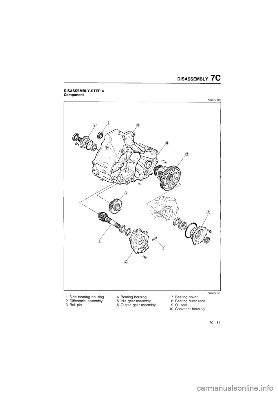
DISASSEMBLY 7C
DISASSEMBLY-STEP 4
Component
76G07C-120
76G07C-121
1. Side bearing housing
2. Differential assembly
3. Roll pin
4. Bearing housing
5. Idle gear assembly
6. Output gear assembly
7. Bearing cover
8. Bearing outer race
9. Oil seal
10. Converter housing
7C—51
Page 1166 of 1865

7C DISASSEMBLY
76G07C-122
76G07C-123
76G07C-124
Procedure
1. Remove the side bearing housing installation bolts
from the transaxle case.
2. Remove the side bearing housing from the trans-
axle case by tapping lightly with a plastic hammer.
3. Remove the differential assembly.
4. Remove the bearing housing.
(1) Remove the bolt indicated in the figure (arrow).
(2) Remove the roll pin with a pin punch.
(3) Remove the bearing housing by tapping light-
ly with a plastic hammer.
76G07C-125
7C-52
Page 1193 of 1865

INSPECTION AND REPAIR 7C
DIFFERENTIAL
Disassembly
Disassemble in the sequence shown in the figure, referring to the disassembly note for specially marked
parts.
1. Roll pin
2. Side gear
3. Side gear thrust washer
4. Pinion shaft
5. Pinion gear
Dial aauae
76G07C-212
6. Pinion gear thrust washer
7. Side bearing inner race
8. Speedometer drive gear
9. Ring gear and gear case assembly
Disassembly note
Checking backlash
Before disassembly, measure the backlash of the side
gears and pinion gears. If not within specification, re-
place the differential assembly.
Backlash:
Standard 0.025—0.1 mm (0.001—0.004 in)
Maximum 0.5 mm (0.020 in)
86U07B-323
7C-79
Page 1194 of 1865

7C INSPECTION AND REPAIR
76G07C-213
86U07B-325
Roll pin
To remove the roll pin from the pinion shaft, place
the gear case on a vise and knock the pin out with
a suitable pin punch (04.0 mm (0.157 in) ) and
hammer.
Note
a) Use the protective plates in the vice to pre-
vent damage to the differential.
b) Insert the punch into the roll pin hole from
the ring gear side.
Side bearing inner race
1. Remove the side bearing inner race (side oppo-
site the ring gear) from the gear case with the SST.
2. Remove the side bearing inner race (ring gear side)
with a combination of parts from the SST.
86U07B-326
Inspection
Check the following and replace any faulty parts.
1. Damaged or worn gears
2. Cracked or damaged gear case
3. Damaged bearings
86U07B-327
7C-80
Page 1196 of 1865

7C INSPECTION AND REPAIR
•Jo V-sVOJ
V-^ sy \
^ I
Dial indicator
Pinion gear
A
86U07B-332
6. Install the thrust washers and side gears into the
gear case at the same time, then turn them back
on the pinion gear and align them with the pinion
shaft hole.
7. Check and adjust the backlash of the side gears
and pinion gears as follows:
(1) Install the left and right driveshafts in the
differential assembly.
(2) Support the driveshafts on V-blocks.
(3) Measure the backlash of both pinion gears.
Backlash:
Standard 0.025—0.1 mm (0.001—0.004 in)
Maximum 0.5 mm (0.020 in)
8.
If
the backlash is not within specification, place the
differential assembly.
86U07B-333
OUTPUT GEAR
Disassembly
Disassemble in the sequence shown in the figure, referring to the disassembly note for specially marked
parts.
1. Output gear
bearing
2. Output gear
bearing
3. Output gear
76G07C-214
7C—82