differential MAZDA 626 1987 Repair Manual
[x] Cancel search | Manufacturer: MAZDA, Model Year: 1987, Model line: 626, Model: MAZDA 626 1987Pages: 1865, PDF Size: 94.35 MB
Page 1208 of 1865

7C ASSEMBLY
3. Adjust the differential side bearing preload and select the adjust shim(s) as described below.
Note
To inspect and adjust the preload, use the SST shown below.
76G07C-242
(1) Remove the side bearing housing race and ad-
just shims from the transaxle case. (Refer to
page 7C—88.)
(2) Set the differential assembly into the convert-
er housing.
(3) Install the outer race removed in step (1) into
the SST; then set them on the differential as-
sembly.
Caution
Eliminate the gap by turning either A or B of
the selector.
7C-94
Page 1210 of 1865

7C ASSEMBLY
(9) Insert the SST through the oil seal hole of the
transaxle case and attach
it
to the pinion shaft.
(10) Mount the SST and pull scale or torque
wrench.
(11) Widen the clearance between A and B to ob-
tain the specified preload/pull scale reading.
Preload:
0.5 N-m (5 cm-kg, 4.3 in-lb)
Reading on pull scale: 5 N (0.5 kg, 1.1 lb)
Note
Read the preload when the differential starts
to turn.
(12) Measure the clearance between A and B.
(13) Add 0.15 mm (0.0059 in) to the measured
clearance, and select the shim(s) closest in
valve to that measurement.
76G07C-246
Thickness
of
shim
0.10
mm
(0.004
in)
0.12
mm
(0.005
in)
0.14
mm
(0.006
in)
0.16
mm
(0.0063
in)
0.18 mm (0.007
in)
0.20 mm (0.008
in)
0.50 mm (0.020
in)
0.70
mm
(0.028
in)
1.00 mm (0.039
in)
76G07C-247
Caution
a) Measure the clearance around the entire cir-
cumference, and select shims equivalent to
the maximum clearance.
b)The maximum allowable number of shims
is 3.
(14) Remove the transaxle case and selector.
(15) Install the required shim(s) and tap the bear-
ing race into the side bearing housing.
76G07C-248
7C-96
Page 1221 of 1865

ASSEMBLY 7C
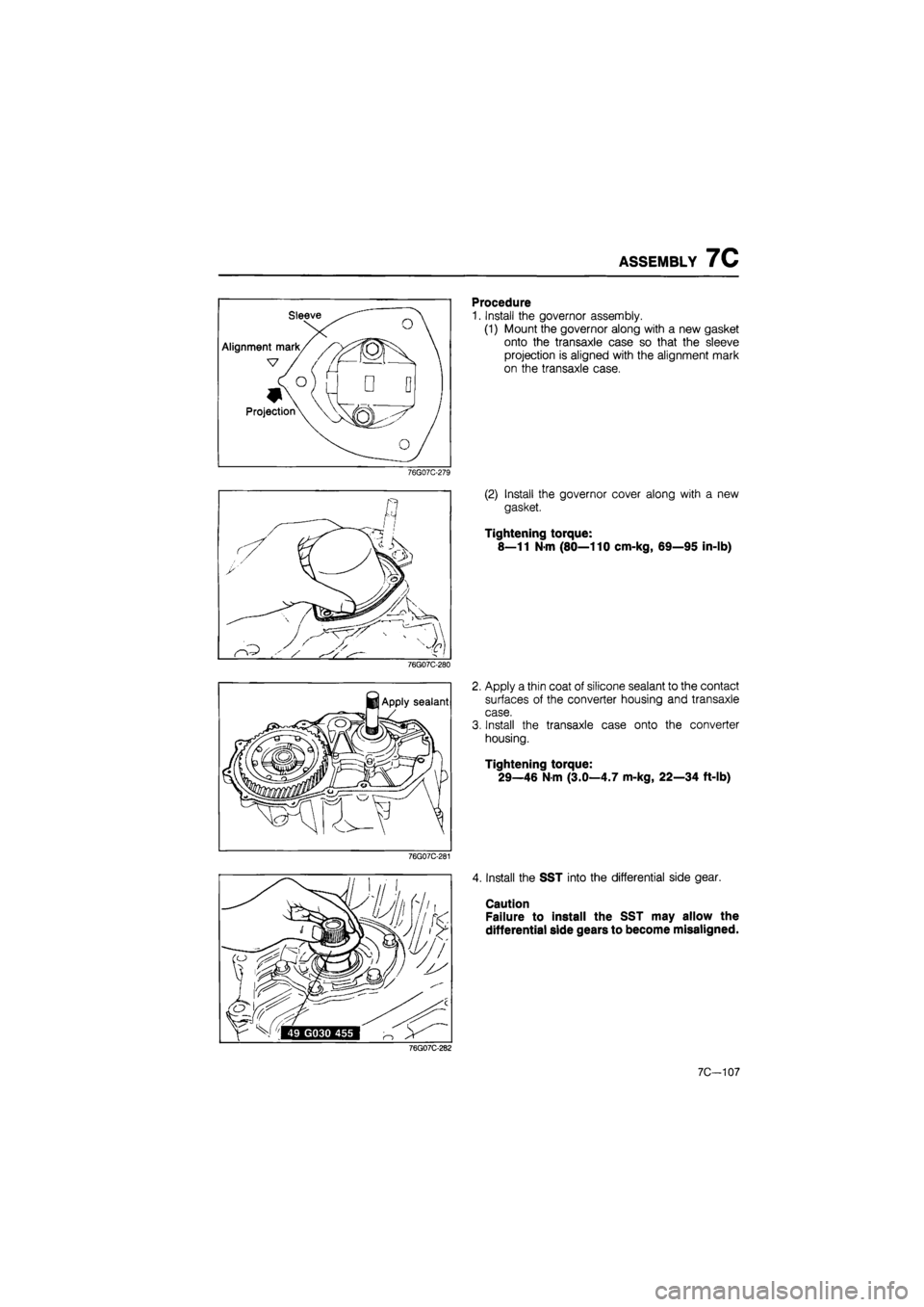
76G07C-279
76G07C-280
76G07C-281
Procedure
1. Install the governor assembly.
(1) Mount the governor along with a new gasket
onto the transaxle case so that the sleeve
projection is aligned with the alignment mark
on the transaxle case.
(2) Install the governor cover along with a new
gasket.
Tightening torque:
8—11 N-m (80—110 cm-kg, 69—95 in-lb)
2. Apply a thin coat of silicone sealant to the contact
surfaces of the converter housing and transaxle
case.
3. Install the transaxle case onto the converter
housing.
Tightening torque:
29—46 N-m (3.0—4.7 m-kg, 22—34 ft-lb)
4. Install the SST into the differential side gear.
Caution
Failure to install the SST may allow the
differential side gears to become misaligned.
76G07C-282
7C-107
Page 1236 of 1865

7C INSTALLATION
(3) Install and tighten the reamer bolts, then install
and tighten the standard bolts.
Tightening torque:
Reamer bolts 7—10 N-m
(70—100 cm-kg, 61—87 in-lb)
Standard bolts 42—62 N m
(4.3—6.3 m-kg, 31—46 ft-lb)
(4) Pull the front hub outward to connect the
driveshaft to the joint shaft.
(5) Push the joint from the differential side to se-
curely connect the driveshaft to the joint shaft.
Caution
a) Do not damage the oil seal.
b) After installation, pull the front hub outward
to verify that the driveshaft is secured.
Install the left driveshaft as follows:
(1) Pull the front hub outward to insert the
driveshaft into the transaxle.
(2) Push the joint from the differential side to con-
nect the driveshaft to the differential side gear.
Caution
a) Do not damage the oil seal.
b) After installation, pull the front hub outward
to verify that the driveshaft is secured.
Install the lower arm ball joints to the knuckles and
tighten the bolts and nuts.
Tightening torque:
36—54 N-m (3.7—5.5 m-kg, 27—40 ft-lb)
Install the under cover.
Install the stabilizer bar control link as follows:
(1) Install the stabilizer bar control link.
(2) Adjust length A to 20.1 mm (0.79 in).
(3) Tighten bolt B to the specified torque.
Tightening torque:
16—23 N-m (1.6—2.3 m-kg, 12—17 ft-lb)
Install the tie-rod ends and cotter pins.
Tightening torque:
29—44 N-m (3.0—4.5 m-kg, 22—33 ft-lb)
7C-122
Page 1251 of 1865

9 OUTLINE
OUTLINE
STRUCTURAL VIEW
Driveshaft (MTX)
86U09X-080
1. Lock nut
2. Shaft and ball joint as-
sembly
3. Boot
4. Boot band
5. Ball joint assembly
(differential side)
6. Snap ring
7. Clip
8. Clip
9. Joint shaft assembly
10. Reamer bolt
11. Bracket mounting bolt
9—2
Page 1279 of 1865

9 DRIVESHAFT
86U09X-055
86U09X-056
Driveshaft
Disconnect the driveshaft from the transaxle with a
prybar.
Note
Do not damage the boot or the oil seal.
Joint shaft
As shown in the figure, insert a pry bar between the
driveshaft and the joint shaft and tap on the bar to
uncouple them.
Front wheel hub
Use the SST to push the shaft out if it is stuck in the
front wheel hub.
86U09X-057
Differential
Install the SST to hold the side gear after removing
the driveshaft.
86U09X-058
9—30
Page 1280 of 1865
![MAZDA 626 1987 Repair Manual
DRIVESHAFT 9
[MTX]
DISASSEMBLY
Disassemble in the sequence shown in the figure referring to the disassembly note for specially marked
parts.
Note
a) Clamp the shaft in a vice. Use protectors in MAZDA 626 1987 Repair Manual
DRIVESHAFT 9
[MTX]
DISASSEMBLY
Disassemble in the sequence shown in the figure referring to the disassembly note for specially marked
parts.
Note
a) Clamp the shaft in a vice. Use protectors in](/img/28/57059/w960_57059-1279.png)
DRIVESHAFT 9
[MTX]
DISASSEMBLY
Disassemble in the sequence shown in the figure referring to the disassembly note for specially marked
parts.
Note
a) Clamp the shaft in a vice. Use protectors in the vice to avoid damage.
b)Do not allow dirt or foreign matter in the joint during disassembly or assembly.
c) Do not disassemble the ball-joint at the wheel side. Do not wipe the grease off if there
is no problem.
d)Do not remove the clip used to secure the outer ring to the ball-joint at the differential
side if there is no problem.
If the clip is removed, replace it with a new one.
1. Boot band
2. Clip
3. Outer ring
4. Snap ring
86U09X-059
5. Ball joint
6. Boot band
7. Boot
8. Clip
9. Sensor rotor (Refer to Section 11)
Clip
1. Make matching marks on the driveshaft and out-
er ring for proper reassembly.
Note
Mark with paint, do not use a punch.
2. Remove the clip.
86U09X-091
9-31
Page 1282 of 1865

DRIVESHAFT 9
ASSEMBLY
Boot
Wrap the shaft splines with tape before installing the
boot.
86U09X-093
Wheel side
Note
a) The wheel side arid differential side boots
are different as shown in the figure.
b) Fill the inside of the ball joint with the speci-
fied grease included in the kit.
c) Securely fit the boot to the shaft and the
outer race boot grooves.
86U09X-062
Balls, inner ring and cage
1. Align the matching marks and install the balls.
86U09X-094
2. Apply molybdenum disulfide grease to the joint.
Note
Do not use other than specified grease.
86U09X-095
9-33
Page 1285 of 1865

9 DRIVESHAFT
INSPECTION
Check and replace any faulty parts.
1. Twisted, bent, or damaged shaft.
2. Wear or scoring of splines.
3. Wear, excessive looseness, seizure, rust, or dam-
age of bearing.
4. Checking, damage, or deterioration of boots.
5. Excessive play or heat damage of joint shaft
bearing.
86U09X-066
Wheel side Differential side
86U09X-067
ASSEMBLY
Assemble in the reverse order of disassembly, refer-
ring to assembly note.
Assembly Note
Note
a) The wheel side and differential side boots
are different as shown in the figure.
b) Fill the inside of the ball joint with the speci-
fied grease included in the kit.
c) Securely fit the boot to the shaft and the
outer race boot grooves.
Tripod joint
Install the snap ring to the joint.
86U09X-068
Clip
Install a new clip.
86U09X-069
9-36
Page 1828 of 1865

30 TECHNICAL DATA
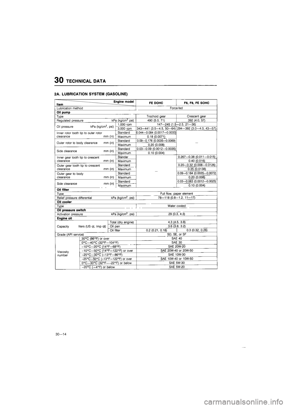
2A. LUBRICATION SYSTEM (GASOLINE)
Engine model Item ____ FE DOHC F6, F8, FE SOHC
Lubrication method Force-fed
Oil pump
Type Trochoid gear Crescent gear
Regulated pressure kPa (kg/cm2
psi)
490 (5.0,
71)
392 (4.0, 57)
Oil pressure kPa (kg/cm2,
psi)
1,000 rpm 147-245 (1.5-2.5, 21-36) Oil pressure kPa (kg/cm2,
psi)
3,000
rpm
343—441 (3.5-4.5, 50-64) 294—392 (3.0—4.0, 43-57)
Inner rotor tooth
tip to
outer rotor
clearance
mm
(in)
Standard 0.044-0.084 (0.0017-0.0033)
—
Inner rotor tooth
tip to
outer rotor
clearance
mm
(in) Maximum 0.18 (0.0071)
—
Outer rotor
to
body clearance
mm
(in) Standard 0.09-0.176 (0.0035-0.0069)
—
Outer rotor
to
body clearance
mm
(in) Maximum 0.20 (0.008)
—
Side clearance
mm
(in) Standard 0.03-0.09 (0.0012-0.0035)
—
Side clearance
mm
(in) Maximum 0.10 (0.004)
—
Inner gear tooth tip
to
crescent clearance
mm
(in)
Standar
—
0.267-0.38 (0.011-0.015) Inner gear tooth tip
to
crescent clearance
mm
(in) Maximum
—
0.40 (0.016)
Outer gear tooth tip
to
crescent clearance
mm
(in)
Standard
—
0.20-0.32 (0.008-0.0126) Outer gear tooth tip
to
crescent clearance
mm
(in) Maximum
—
0.35 (0.0138)
Outer gear
to
body
clearance
mm
(in)
Standard
—
0.09-0.184 (0.0035-0.0072) Outer gear
to
body
clearance
mm
(in) Maximum
—
0.20 (0.008)
Side clearance mm (in) Standard
—
0.03-0.063 (0.0012-0.0025) Side clearance mm (in) Maximum
—
0.10 (0.004)
Oil filter
Type Full flow, paper element
Relief pressure differential kPa (kg/cm2,
psi)
78-118 (0.8-1.2, 11-17)
Oil cooler
Type
!
Water cooled
Oil pressure switch
Activation pressure kPa (kg/cm2,
psi)
29 (0.3, 4.3)
Enaine oil
Capacity liters (US qt, Imp
qt)
Total (drv enaine) 4.3 (4.5, 3.8)
Capacity liters (US qt, Imp
qt)
Oil
Dan
3.6 (3.8, 3.2) Capacity liters (US qt, Imp
qt)
Oil filter 0.2(0.21,0.18)
|
0.3 (0.32,0.26)
Grade (API service) SD, SE,
or
SF
Viscosity
number
30°C (86°F)
or
over SAE
40
Viscosity
number
0°C—40°C (32°F—104°F) SAE
30
Viscosity
number
-10°C—20°C (14°F—68°F) SAE 20W-20
Viscosity
number
-10°C—50°C (14°F—122°F)
or
over SAE 20W-40
or
20W-50 Viscosity
number -25°C—30°C (-13°F—86°F) SAE 10W-30 Viscosity
number
-25°C—50°C (-13°F—122°F)
or
over SAE 10W-40
or
10W-50
Viscosity
number
0°C—30°C (32°F—22°F)
or
below SAE 5W-30
Viscosity
number
-20°C (—4°F)
or
below SAE 5W-20
30-14