oil MAZDA 626 1987 Workshop Manual
[x] Cancel search | Manufacturer: MAZDA, Model Year: 1987, Model line: 626, Model: MAZDA 626 1987Pages: 1865, PDF Size: 94.35 MB
Page 1799 of 1865
16 COMPRESSOR
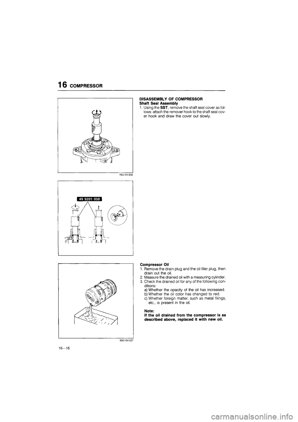
DISASSEMBLY OF COMPRESSOR
Shaft Seal Assembly
1. Using the SST, remove the shaft seal cover as fol-
lows: attach the remover hook to the shaft seal cov-
er hook and draw the cover out slowly.
76G16X-608
Compressor Oil
1. Remove the drain plug and the oil filler plug, then
drain out the oil.
2. Measure the drained oil with a measuring cylinder.
3. Check the drained oil for any of the following con-
ditions:
a) Whether the opacity of the oil has increased.
b) Whether the oil color has changed to red.
c) Whether foreign matter, such as metal filings,
etc., is present in the oil.
Note:
If the oil drained from the compressor is as
described above, replaced it with new oil.
69G16X-037
16—16
Page 1801 of 1865
16 COMPRESSOR
76G16X-611
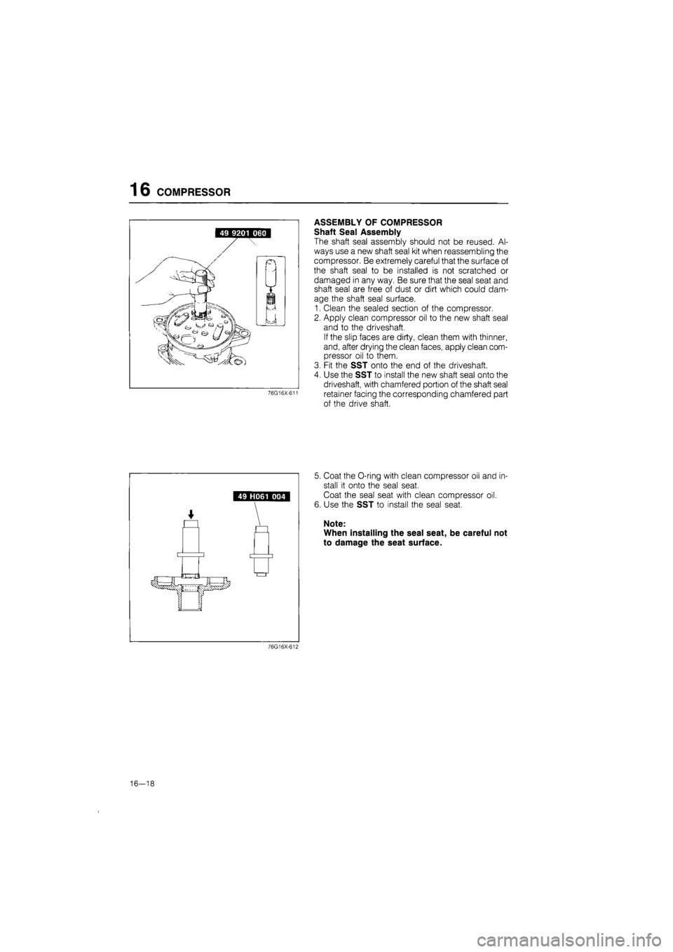
ASSEMBLY OF COMPRESSOR
Shaft Seal Assembly
The shaft seal assembly should not be reused. Al-
ways use a new shaft seal kit when reassembling the
compressor. Be extremely careful that the surface of
the shaft seal to be installed is not scratched or
damaged in any way. Be sure that the seal seat and
shaft seal are free of dust or dirt which could dam-
age the shaft seal surface.
1. Clean the sealed section of the compressor.
2. Apply clean compressor oil to the new shaft seal
and to the driveshaft.
If the slip faces are dirty, clean them with thinner,
and, after drying the clean faces, apply clean com-
pressor oil to them.
3. Fit the SST onto the end of the driveshaft.
4. Use the SST to install the new shaft seal onto the
driveshaft, with chamfered portion of the shaft seal
retainer facing the corresponding chamfered part
of the drive shaft.
5. Coat the O-ring with clean compressor oil and in-
stall it onto the seal seat.
Coat the seal seat with clean compressor oil.
6. Use the SST to install the seal seat.
Note:
When installing the seal seat, be careful not
to damage the seat surface.
76G16X-612
16-18
Page 1802 of 1865
COMPRESSOR 16
Escape groove
^ / / / / j / / ' / / / / /
' / / I / /
1 \ \ x Suction \ \ \/ valve
n W: \ / / y /
I u
Piston— ^
69G16X-044
69G16X-045
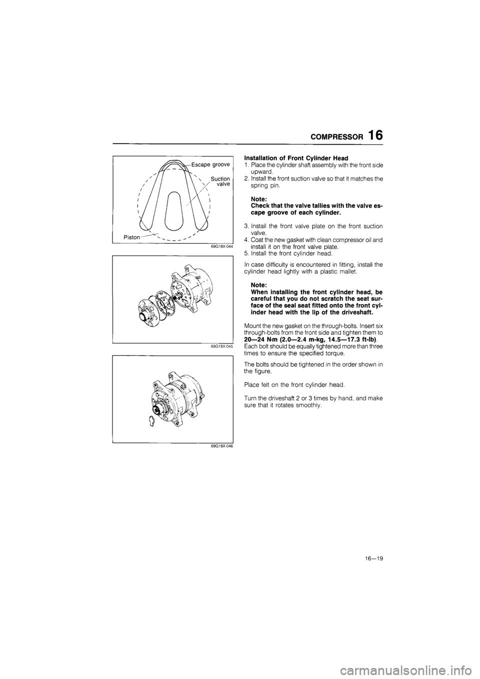
Installation of Front Cylinder Head
1. Place the cylinder shaft assembly with the front side
upward.
2. Install the front suction valve so that it matches the
spring pin.
Note:
Check that the valve tallies with the valve es-
cape groove of each cylinder.
3. Install the front valve plate on the front suction
valve.
4. Coat the new gasket with clean compressor oil and
install it on the front valve plate.
5. Install the front cylinder head.
In case difficulty is encountered in fitting, install the
cylinder head lightly with a plastic mallet.
Note:
When installing the front cylinder head, be
careful that you do not scratch the seat sur-
face of the seal seat fitted onto the front cyl-
inder head with the lip of the driveshaft.
Mount the new gasket on the through-bolts. Insert six
through-bolts from the front side and tighten them to
20—24 N m (2.0—2.4 m-kg, 14.5—17.3 ft-lb)
Each bolt should be equally tightened more than three
times to ensure the specified torque.
The bolts should be tightened in the order shown in
the figure.
Place felt on the front cylinder head.
Turn the driveshaft 2 or 3 times by hand, and make
sure that it rotates smoothly.
69G16X046
16—19
Page 1803 of 1865
16 COMPRESSOR
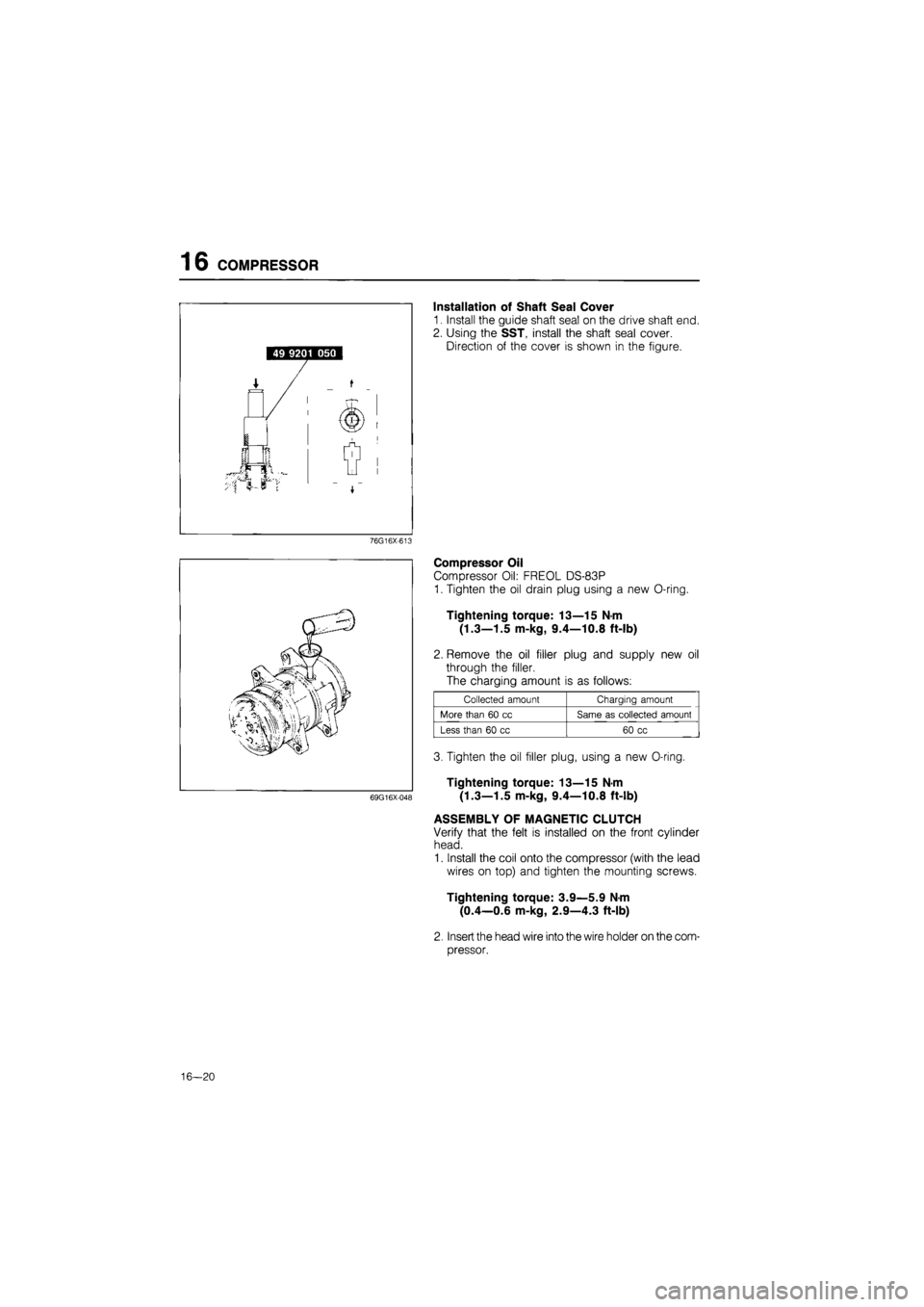
Installation of Shaft Seal Cover
1. Install the guide shaft seal on the drive shaft end.
2. Using the SST, install the shaft seal cover.
Direction of the cover is shown in the figure.
76G16X-613
69G16X-048
Compressor Oil
Compressor Oil: FREOL DS-83P
1. Tighten the oil drain plug using a new O-ring.
Tightening torque: 13—15 N-m
(1.3—1.5 m-kg, 9.4—10.8 ft-lb)
2. Remove the oil filler plug and supply new oil
through the filler.
The charging amount is as follows:
Collected amount Charging amount
More than
60 cc
Same
as
collected amount
Less than
60 cc
60
cc
3. Tighten the oil filler plug, using a new O-ring.
Tightening torque: 13—15 N-m
(1.3—1.5 m-kg, 9.4—10.8 ft-lb)
ASSEMBLY OF MAGNETIC CLUTCH
Verify that the felt is installed on the front cylinder
head.
1. Install the coil onto the compressor (with the lead
wires on top) and tighten the mounting screws.
Tightening torque: 3.9—5.9 N-m
(0.4—0.6 m-kg, 2.9—4.3 ft-lb)
2. Insert the head wire into the wire holder on the com-
pressor.
16—20
Page 1807 of 1865
16 CONDENSER
CONDENSER
ON-VEHICLE INSPECTION
1. Check the condenser fins for blockage or damage.
If the fins are clogged, clean them with compressed air.
If the fins are bent, straighten them with a screwdriver or pair of pliers.
2. Check the condenser fittings for leakage.
Repair or replace, if necessary.
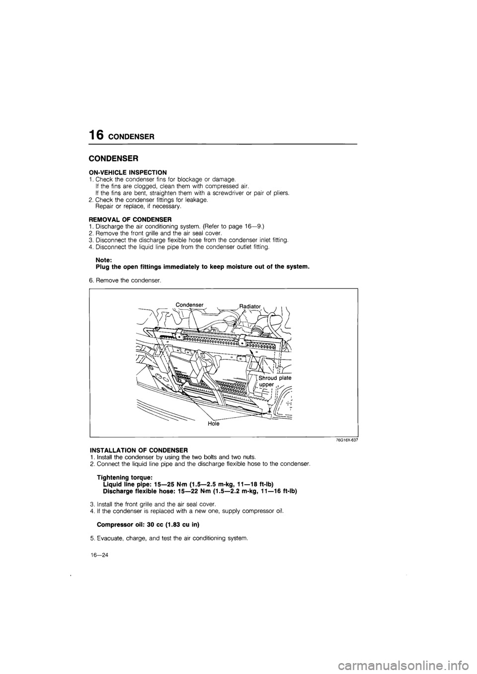
REMOVAL OF CONDENSER
1. Discharge the air conditioning system. (Refer to page 16—9.)
2. Remove the front grille and the air seal cover.
3. Disconnect the discharge flexible hose from the condenser inlet fitting.
4. Disconnect the liquid line pipe from the condenser outlet fitting.
Note:
Plug the open fittings immediately to keep moisture out of the system.
6. Remove the condenser.
Condenser Radiator
Hole
76G16X-637
INSTALLATION OF CONDENSER
1. Install the condenser by using the two bolts and two nuts.
2. Connect the liquid line pipe and the discharge flexible hose to the condenser.
Tightening torque:
Liquid line pipe: 15—25 Nm (1.5—2.5 m-kg, 11—18 ft-lb)
Discharge flexible hose: 15—22 N-m (1.5—2.2 m-kg, 11—16 ft-lb)
3. Install the front grille and the air seal cover.
4. If the condenser is replaced with a new one, supply compressor oil.
Compressor oil: 30 cc (1.83 cu in)
5. Evacuate, charge, and test the air conditioning system.
16—24
Page 1808 of 1865
RECEIVER-DRIER 16
RECEIVER-DRIER
ON-VEHICLE INSPECTION
1. Use a leak detector to check the sight glass, the
fusible plug, and the fittings for leakage.
Repair or replace, if necessary.
2. Check the receiver-drier for clogging.
a) Run the engine at fast idle with the air conditioner
on.
b) Check both inlet and outlet temperatures.
If there is a great difference between the two tem-
peratures, replace the receiver-drier.
76G16X-622
Receiver-drier
Condenser bolt
76G16X-638
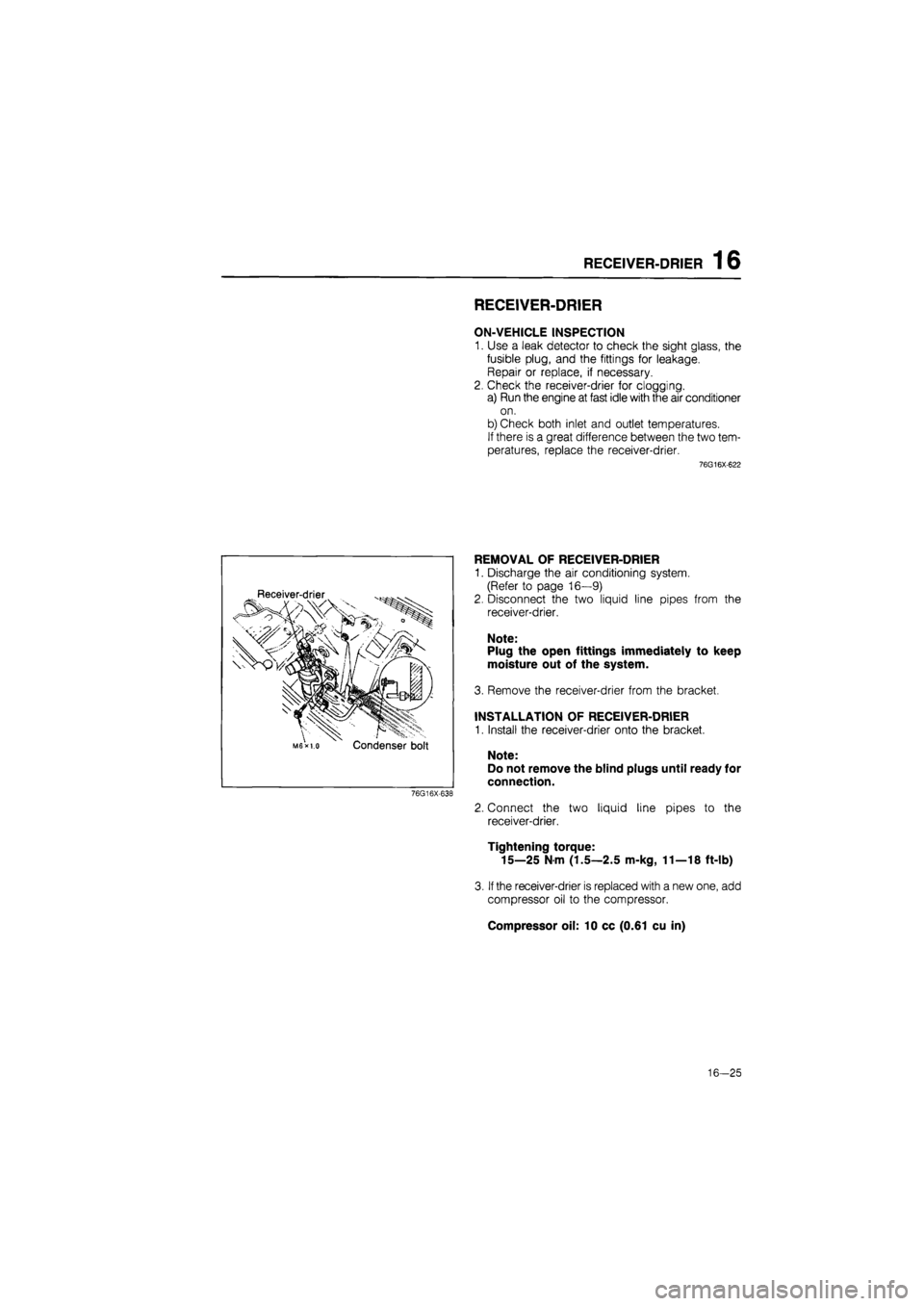
REMOVAL OF RECEIVER-DRIER
1. Discharge the air conditioning system.
(Refer to page 16—9)
2. Disconnect the two liquid line pipes from the
receiver-drier.
Note:
Plug the open fittings immediately to keep
moisture out of the system.
3. Remove the receiver-drier from the bracket.
INSTALLATION OF RECEIVER-DRIER
1. Install the receiver-drier onto the bracket.
Note:
Do not remove the blind plugs until ready for
connection.
2. Connect the two liquid line pipes to the
receiver-drier.
Tightening torque:
15—25 N m (1.5—2.5 m-kg, 11—18 ft-lb)
3.
If
the receiver-drier is replaced with a new one, add
compressor oil to the compressor.
Compressor oil: 10 cc (0.61 cu in)
16-25
Page 1811 of 1865

1 6 COOLING UNIT
INSTALLATION OF COOLING UNIT
1. Install the cooling unit by using the two nuts.
Note
Adjust and position the unit so that its con-
nections match those of the heater unit and
the blower unit.
2. Connect the drain hose.
76G16X-625
Sealing plate
Heater I _ .. ' . . - V
unit Evaporator dealing plate Blower unit
3. Join the connections on both sides by using the
seal plates.
4. Connect the A/C harness to the cooling unit.
76G16X-626
76G16X-627
5. Connect the liquid line high-pressure pipe and suc-
tion low-pressure pipe to the cooling unit.
Tightening torque:
15—22 Nm (1.5—2.5 m-kg, 11—18 ft-lb)
6. Install the instrument lower panel, shower duct and
glove box.
7. If the evaporator is replaced, add compressor oil
to the compressor.
Compressor oil: 50 cc (3.05 cu in)
16-28
Page 1817 of 1865

TECHNICAL DATA 30
FE 12-valve Item FE 12-valve
Valve seat
Seat angle IN 45° Seat angle EX 45°
Seat contact width mm (in) IN 1.2-1.6 (0.047-0.063) Seat contact width mm (in) EX 1.2-1.6 (0.047-0.063)
Seat sinking (Measure valve protruding length) mm (in)
IN Standard 50.2 (1.976) Seat sinking (Measure valve protruding length) mm (in)
IN Maximum 51.0 (2.008) Seat sinking (Measure valve protruding length) mm (in) EX Standard 50.2 (1.976)
Seat sinking (Measure valve protruding length) mm (in) EX Maximum 51.0 (2.008)
Valve spring
IN Standard 49.5 (1.949)
Free length
mm
(in)
IN Minimum 49.0 (1.929) Free length
mm
(in)
EX Standard 50.4 (1.984) EX Minimum 48.7 (1.917)
Out-of-square mm (in) Maximum 1.8 (0.071)
Setting load/height
N
(kg, lb)/mm (in) IN 203-230 (20.7-23.4, 45.5-51,5)/41 (1.614) Setting load/height
N
(kg, lb)/mm (in) EX 240-272 (24.5—27.7, 53.9-60.9)/41 (1.614)
Camshaft
IN Standard 41.290-41.390 (1.6256-1.6295)
Cam lobe height
mm
(in)
IN Minimum 41.140 (1.6197) Cam lobe height
mm
(in)
EX Standard 41.797-41.897 (1.6455—1.6495) EX Minimum 41.647 (1.6396)
Front and Rear (No.
1,5)
31.940-31.965 (1.2575-1.2585)
Journal diameter
mm (in)
Center (No. 2,3,4) 31.910-31.935 (1.2563-1.2573)
Out-of-round Maximum 0.05 (0.002)
Camshaft bearing
oil
clearance
mm
(in)
Front and Rear (No.
1,5)
0.035—0.085 (0.0014-0.0033) Camshaft bearing
oil
clearance
mm
(in) Center (No. 2,3,4) 0.065-0.115 (0.0026-0.0045) Camshaft bearing
oil
clearance
mm
(in) Maximum 0.15 (0.0059)
Camshaft runout mm (in) Maximum 0.03 (0.0012)
Camshaft end play mm (in) Standard 0.08-0.16 (0.003—0.0061 Camshaft end play mm (in) Maximum 0.20 (0.008)
Rocker arm and rocker arm shaft
Rocker arm inner diameter mm (in) 19.000—19.033 (0.748—0.749)
Rocker arm shaft diameter mm (in) 18.959-18.980 (0.746-0.747)
Rocker arm
to
shaft clearance mm (in) Standard 0.020-0.074 (0.0008-0.0029) Rocker arm
to
shaft clearance mm (in) Maximum 0.10 (0.004)
Cylinder block
Height mm (in) 289.0 (11.38)
Distortion mm (in) Maximum 0.15 (0.006)
Grinding limit mm (in) 0.20 (0.008)
Cylinder bore diameter
mm (in)
Standard 86.000—86.019 (3.3858-3.3866) Cylinder bore diameter
mm (in) 0.25 (0.010) oversize 86.250-86.269 (3.3957-3.3964) Cylinder bore diameter
mm (in) 0.50 (0.020) oversize 86.500-86.519 (3.4055-3.4062)
Cylinder bore taper and out-of-round mm (in) Maximum 0.019 (0.0007)
Piston
Piston diameter measured at 90°
to
pin bore axis and 18.0 mm (0.709
in)
below oil ring groove
mm (in)
Standard 85.944-85.964 (3.3836-3.3844) Piston diameter measured at 90°
to
pin bore axis and 18.0 mm (0.709
in)
below oil ring groove
mm (in)
0.25 (0.010) oversize 86.194-86.214 (3.3935—3.3942)
Piston diameter measured at 90°
to
pin bore axis and 18.0 mm (0.709
in)
below oil ring groove
mm (in) 0.50 (0.020) oversize 86.444-86.464 (3.4033—3.4041)
Piston
to
cylinder clearance mm (in) Standard 0.036-0.075 (0.0014-0.0030) Piston
to
cylinder clearance mm (in) Maximum 0.15 (0.0059)
Piston ring
Thickness mm (in)
TOD
1.47-1.49 (0.0579—0.05871 Thickness mm (in) Second 1.47-1.49 (0.0579-0.0587)
30-3
Page 1818 of 1865

30 TECHNICAL DATA
Item Engine model FE 12-valve
Top 0.20—0.35 (0.008-0.0138)
End gap measured
in
cylinder
mm
(in) Second 0.15—0.30 (0.006-0.012) End gap measured
in
cylinder
mm
(in) Oil (rail) 0.20-0.70 (0.008-0.0276)
Maximum 1.0 (0.039)
Top 1.52-1.54 (0.0598-0.0606)
Ring groove width
in
piston mm (in) Second 1.52-1.54 (0.0598-0.0606)
Oil 4.02-4.04 (0.1583-0.1591)
Top 0.03—0.07 (0.0012—0.0028) Clearance
ot
piston ring
to
ring Second 0.03—0.07 (0.0012-0.0028)
Maximum 0.15(0.006)
Piston pin
Diameter mm (in) 21.974-21.980 (0.8651-0.8654)
Interference
in
connecting
rod
mm (in) 0.013-0.037 (0.0005-0.0015)
Piston
to
piston pin clearance mm (in) 0.008-0.024 (0.0003—0.0009)
Installation pressure N (kg,
lb)
4,900-14,700 (500-1,500, 1,100-3,300)
Connecting rod and connecting rod bearing
Length (Center
to
center) mm (in) 151.95—152.05 (5.982—5.986)
Twisting and bending mm (in) 0.06 (0.0024) max.
Small end bore mm (in) 21.943—21.961 (0.8640-0.8646)
Big end bore mm (in) 54.002-54.017 (2.1261—2.1266)
Big end width mm (in) 26.838-26.890 (1.0566—1.0587)
Connecting rod side clearance
mm
(in) Standard 0.110-0.262 (0.004-0.010) Connecting rod side clearance
mm
(in) Maximum 0.30 (0.012)
Crankshaft
Crankshaft runout mm (in) Maximum 0.03 (0.0012)
Standard size 59.937-59.955 (2.3597—2.3604)
0.25 (0.010) Standard 59.693-59.711 (2.3501-2.3508)
Main journal diameter mm (in)
undersize No.3 59.687-59.705 (2.3499-2.3506) Main journal diameter mm (in) 0.50 (0.020) No. 1,2,4,5 59.443-59.461 (2.3403-2.3410) Main journal diameter mm (in) undersize No.
3
59.437-59.455 (2.3400-2.3407)
0.75 (0.030) No. 1,2,4,5 59.193-59.211 (2.3304-2.3311)
undersize No.
3
59.187-59.205 (2.3302-2.3309)
Main journal taper and out-of-round mm (in) Maximum 0.05 (0.0020)
Standard 50.940-50.955 (2.0055-2.0061)
Crankpin diameter 0.25 (0.010) undersize 50.690—50.705 (1.9957-1.9963)
mm (in) 0.50 (0.020) undersize 50.440-50.455 (1.9858-1.9864)
0.75 (0.030) undersize 50.190-50.205 (1.9760-1.9766)
Crankpin taper and out-of-round
mm (in)
Maximum 0.05 (0.0020)
Main bearing
No. 1,2,4,5 Standard 0.025-0.043 (0.0010—0.0017)
Main journal bearing
oil
No. 1,2,4,5 Maximum 0.08 (0.0031) clearance
mm
(in) No.
3
Standard 0.031—0.049 (0.0012—0.0019) No.
3
Maximum 0.08 (0.0031)
Available undersize bearing mm fin} 0.25 (0.010), 0.50 (0.020), 0.75 (0.030)
Crankpin bearing
Crankpin bearing
oil
clearance
mm
(in) Standard 0.027-0.067 (0.0011-0.0026) Crankpin bearing
oil
clearance
mm
(in) Maximum 0.10 (0.0039)
Available undersize bearina mm (in) 0.25 (0.010), 0.50 (0.020), 0.75 (0.030)
Thrust bearing (center main bearing)
Crankshaft end play mm (in) Standard 0.08-0.18 (0.0031-0.0071) Crankshaft end play mm (in) Maximum 0.30 (0.0118)
Standard 27.94-27.99 (1.100-1.102)
Bearing width
mm (in)
0.25 (0.010) oversize 28.04-28.09 (1.104-1.106) Bearing width
mm (in)
0.50 (0.020) oversize 28.12-28.17 (1.107-1.109)
0.75 (0.030) oversize 28.20—28.25 (1.110—1.112)
30—4
Page 1820 of 1865

30 TECHNICAL DATA
Engine model FE 8-valve
Item ECE Middle East General
F8 F6
Valve seat
Seat angle IN 45° Seat angle EX 45°
Seat contact width mm (in) IN 1.2—1.6 (0.047-0.063) Seat contact width mm (in) EX 1.2-1.6 (0.047-0.063)
Seat sinking (Measure valve protruding length)
mm (in)
IN Standard 46.5 (1.831) Seat sinking (Measure valve protruding length)
mm (in)
IN Maximum 48.0 (1.890) Seat sinking (Measure valve protruding length)
mm (in) EX Standard 46.5 (1.831)
Seat sinking (Measure valve protruding length)
mm (in) EX Maximum 48.0 (1.890)
Valve spring
Free length mm (in)
Outer
Inner
Standard
Minimum
51.5(2.028)
Standard
44.0 (1.732)
Minimum
43.3 (1.705)
51.2 (2.016)
52.0 (2.047)
50.6 (1.992)
51.5 (2.028)
45.7 (1.799)
44.0 (1.732)
437 (1.720)1
43.3 (1.705)
Out-of-square mm (in) Maximum 1.8 (0.071)
Setting load/height
N
(kg, lb)/mm
(in)
Outer
128(13.1,29) 136.5
(1
44)
Inner
189 (19,2, 42) 141 (1.61)
124 (12.7, 28) 136.5
(1
44)
193 (19.6,43) 141 (1.61)
128 (13.1, 29)/36.5 (1.44)
189 (19.2, 42)/41 (1.61)
Camshaft
Cam lobe height
mm (in)
IN
EX
Standard
Minimum
Standard
Minimum
38.107-38.207 (1.5003-1.5042)
37.957 (1.4944)
38.110-38.210 (1.5004-1.5043)
37.960 (1.4945)
Journal diameter
mm (in)
Front and Rear (No.
1,5)
31.940-32.035 (1.2575-1.2612)
Center (No. 2,3,4)
Out-of-round Maximum
31.910-32.065 (1.2563-1.2624)
0.05 (0.002)
Camshaft bearing
oil
clearance
mm (in)
Front and Rear (No.
1,5)
0.035-0.085 (0.0014-0.00331
Center (No. 2,3,4) 0.065-0.115 (0.0026—0.0045)
Maximum 0.15 (0.0059)
Camshaft runout mm (in) Maximum 0.03 (0.00121
Camshaft end play mm (in) Standard 0.08—0.16 (0.003—0.006)
Maximum 0.20 (0.008)
Rocker arm and rocker arm shaft
Rocker arm inner diameter mm (in) 16.000-16.027 (0.6299-0.6310)
Rocker arm shaft diameter mm (in) 15.966-15.984 (0.6286-0.6293)
Rocker arm
to
shaft clearance
mm (in)
Standard 0.016—0.061 (0.0006-0.0024)
Maximum 0.10 (0.004)
Cylinder block
Heiaht mm
fin)
289.0 (11.38) 268.5 (10.57)
Distortion mm (in) Maximum 0.15 (0.006)
Grindina limit mm (in)
0.20 (0.008)
Cylinder bore diameter
mm (in)
Standard 86.000—86.019 (3.3858—3.3866)
0.25 (0.010) oversize 86.250-86.269 (3.3957-3.3964)
0.50 (0.020) oversize 86.500-86.519 (3.4055-3.4062)
0.75 (0.030) oversize
1.00 (0.039) oversize
81.000-
(3.1890-
-81.019 -3.1897)
81.250-(3.1988-
-81.269
-3.1996) 81.500-(3.2087-
-81.519 -3.2094)
81.750-(3.2185-
-81.769
-3.2192)
82.000-
(3.2283-
-82.019
-3.2291)
Cylinder bore taper and out-of-round mm (in) Maximum 0.019 (0.0007)
Piston
Piston diameter measured at 90°
to pin
bore axis and 18.0
mm
(0.709
in)
below
oil
ring groove
mm (in)
Standard 85.944-85.964 (3.3836—3.3844) 80.944-80.964
(3.1868—3.1876) Piston diameter measured at 90°
to pin
bore axis and 18.0
mm
(0.709
in)
below
oil
ring groove
mm (in)
0.25 (0.010) oversize 86.194—86.214 (3.3935—3.3942) 81.194—81.214
(3.1966-3.1974)
Piston diameter measured at 90°
to pin
bore axis and 18.0
mm
(0.709
in)
below
oil
ring groove
mm (in) 0.50 (0.020) oversize 86.444-86.464 (3.4033-3.4041) 81.444-81.464
(3.2065-3.2072)
30—6