turn signal MAZDA 626 1987 Workshop Manual
[x] Cancel search | Manufacturer: MAZDA, Model Year: 1987, Model line: 626, Model: MAZDA 626 1987Pages: 1865, PDF Size: 94.35 MB
Page 439 of 1865
![MAZDA 626 1987 Workshop Manual
4A IDLE-UP CONTROL SYSTEM
76G04A-144
76G04A-145
76G04A-146
Vacuum Signal [Equipped with A/C, only FE and
F8 (Except Middle East and General)]
1. Start the engine and run it at idle.
2. Disconn MAZDA 626 1987 Workshop Manual
4A IDLE-UP CONTROL SYSTEM
76G04A-144
76G04A-145
76G04A-146
Vacuum Signal [Equipped with A/C, only FE and
F8 (Except Middle East and General)]
1. Start the engine and run it at idle.
2. Disconn](/img/28/57059/w960_57059-438.png)
4A IDLE-UP CONTROL SYSTEM
76G04A-144
76G04A-145
76G04A-146
Vacuum Signal [Equipped with A/C, only FE and
F8 (Except Middle East and General)]
1. Start the engine and run it at idle.
2. Disconnect the vacuum hose from the servo di-
aphragm.
3. Place a finger over the hose.
4. Increase the engine speed, and check for vacuum.
Engine model Engine speed Vacuum
pj| (Except Middle) Below 2,300 rpm Yes pj| (Except Middle) Above 2,300 rpm No
FE (Unleaded fuel) Below 1,500 rpm Yes FE (Unleaded fuel) Above 1,500 rpm No
F6 (Singapore) Below 2,100 rpm Yes F6 (Singapore) Above 2,100 rpm No
General and Middle East
1. Start the engine and run it at idle.
2. Disconnect the vacuum hose from the servo di-
aphragm.
3. Place a finger over the hose.
4. Operate the A/C or P/S.
5. Check that vacuum is felt.
P/S Switch
1. Start the engine and run it at idle.
2. Disconnect the power steering switch connector.
3. Connect an ohmmeter to the power steering
switch.
4. Turn the steering wheel all the way to either the
right or left, and check for continuity.
P/S Continuity
Operated Yes
Not operated No
5. Replace if necessary.
Solenoid Valve (A/C)
1. Disconnect vacuum hose A from the servo di-
aphragm.
2. Disconnect vacuum hose B from the solenoid
valve.
3. Disconnect the solenoid valve connector.
4. Blow air through the valve from hose A and check
that it comes out of port C.
76G04A-147
4A-74
Page 473 of 1865

TROUBLESHOOTING WITH SST 4B
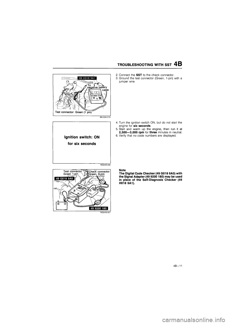
2. Connect the SST to the check connector.
3. Ground the test connector (Green, 1-pin) with a
jumper wire.
86U04A-015
Ignition switch:
ON
for six
seconds
4. Turn the ignition switch ON, but do not start the
engine for six seconds.
5. Start and warm up the engine, then run it at
2,500—3,000 rpm for three minutes in neutral.
6. Verify that no code numbers are displayed.
76G04B-006
76G04B-007
Note
The Digital Code Checker (49 G018 9A0) with
the Signal Adapter (49 9200 180) may be used
in place of the Self-Diagnosis Checker (49
H018 9A1).
4B-11
Page 475 of 1865

TROUBLESHOOTING WITH SST 4B
CODE NUMBER
Malfunction display
Self-diagnosis Fail-safe Code
No. Output signal pattern subsystem Self-diagnosis Fail-safe
01
ON
OFF
Ignition pulse
No ignition signal
08
Air flow meter
Open
or
short circuit
Maintains basic sig-
nal
at
preset value
09
1 111
Water thermo sensor
Open
or
short circuit
Maintains constant command 35°C (95 °F)
10
Intake
air
thermo sensor (air flow meter) Open
or
short circuit
Maintains constant 20°C (68°F) command
12
£_IUILJIIL
Throttle sensor
Open
or
short circuit
Maintains constant
command
of
throttle
valve fully open
14
OFF
TL
I I nil
Atmospheric pres-
sure sensor Open
or
short circuit
Maintains constant command
of
sea level pressure
15
oTp m 11 [U
Oxygen sensor Sensor output con-tinues less than 0.55V 120 sec. after engine starts (1,500 rpm)
Cancels EG
I
feed-
back operation
17
SLJlMJl
Feedback system Sensor output
not
changed
20
sec.
af-
ter engine exceeds 1,500 rpm
Cancels EGI feed-back operation
25
^JMLJl
Solenoid valve (pres-
sure regulator)
Open
or
short circuit
26
SUUBUIL
Solenoid valve (purge control)
Open
or
short circuit 28
£ mi in nr
Solenoid valve
(EGR) Open
or
short circuit
34
^jmiUTT
Air bypass solenoid
valve (Idle-up
C)
Open
or
short circuit
35
0Nnnnj OFFU u UUU
"fin nnr
Air bypass solenoid
valve (Idle-up
B)
Open
or
short circuit
76G04B-008
Caution
a) If there is more than one failure present, the lowest number malfunction code is dis-
played first, the remaining codes are displayed sequentially.
b) After repairing a failure, turn off the ignition switch and disconnect the negative battery
cable and depress the brake pedal for at least 2 seconds to erase the memory of a mal-
function code.
4B-13
Page 488 of 1865

4B SWITCH MONITOR FUNCTION
49 H018 9A1
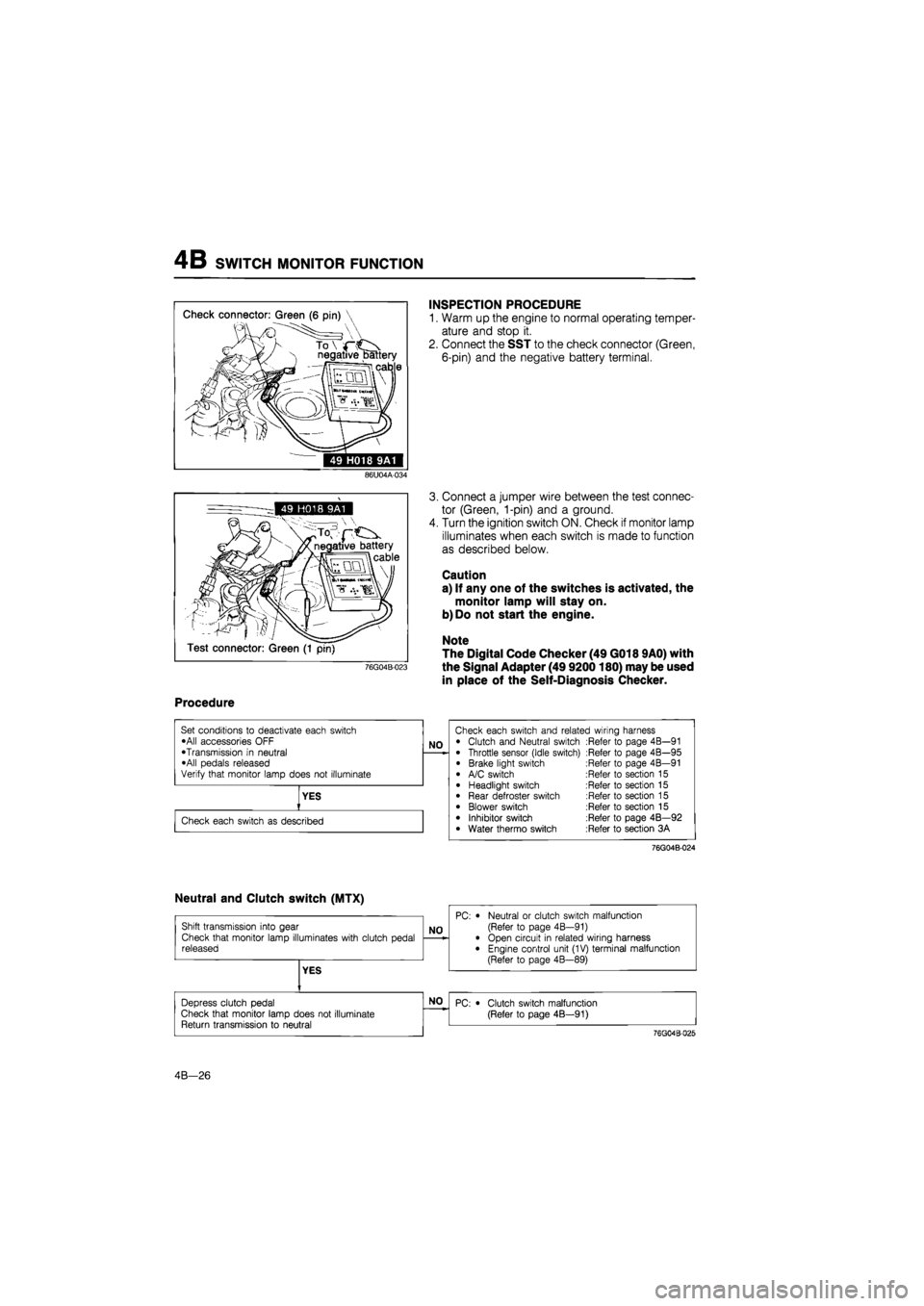
INSPECTION PROCEDURE
1. Warm up the engine to normal operating temper-
ature and stop it.
2. Connect the SST to the check connector (Green,
6-pin) and the negative battery terminal.
86U04A-034
76G04B-023
3. Connect a jumper wire between the test connec-
tor (Green, 1-pin) and a ground.
4. Turn the ignition switch ON. Check if monitor lamp
illuminates when each switch is made to function
as described below.
Caution
a) If any one of the switches is activated, the
monitor lamp will stay on.
b) Do not start the engine.
Note
The Digital Code Checker (49 G018 9A0) with
the Signal Adapter (49 9200180) may be used
in place of the Self-Diagnosis Checker.
Procedure
76G04B-024
4B—26
Page 498 of 1865

4B IDLE-UP SYSTEM
COMPONENT DESCRIPTIONS
Component Function Remarks
Air bypass solenoid
valve
Controls bypass
air
amount Operates A: A/C
: ON
B: Intake
air
temp, high
or at
high
al-
titude C: P/S
:
ON, E/L applied
or
hot start
Air valve
When cold, supplies bypass
air
into
dy-
namic chamber
• Engine speed increased
to
shorten
warm-up period
• Bimetal type
Atmospheric pressure sensor
Detects atmospheric pressure; sends sig-
nal
to
engine control unit
E/L control unit
Detects electrical load applied; sends sig-nal
to
engine control unit
Engine control unit
Detects signals from input sensors and switches; controls
air
bypass solenoid valve
Intake air thermo sensor
Detects intake
air
temperature; sends sig-
nal
to
engine control unit
Installed
in air
flow meter
P/S pressure switch
Detects P/S operation; sends signal
to
engine control unit P/S:
ON
when steering wheel turnefl right
or
left
76g04b-044
4B-36
Page 501 of 1865

IDLE-UP SYSTEM 4B
AIR BYPASS SOLENOID VALVE
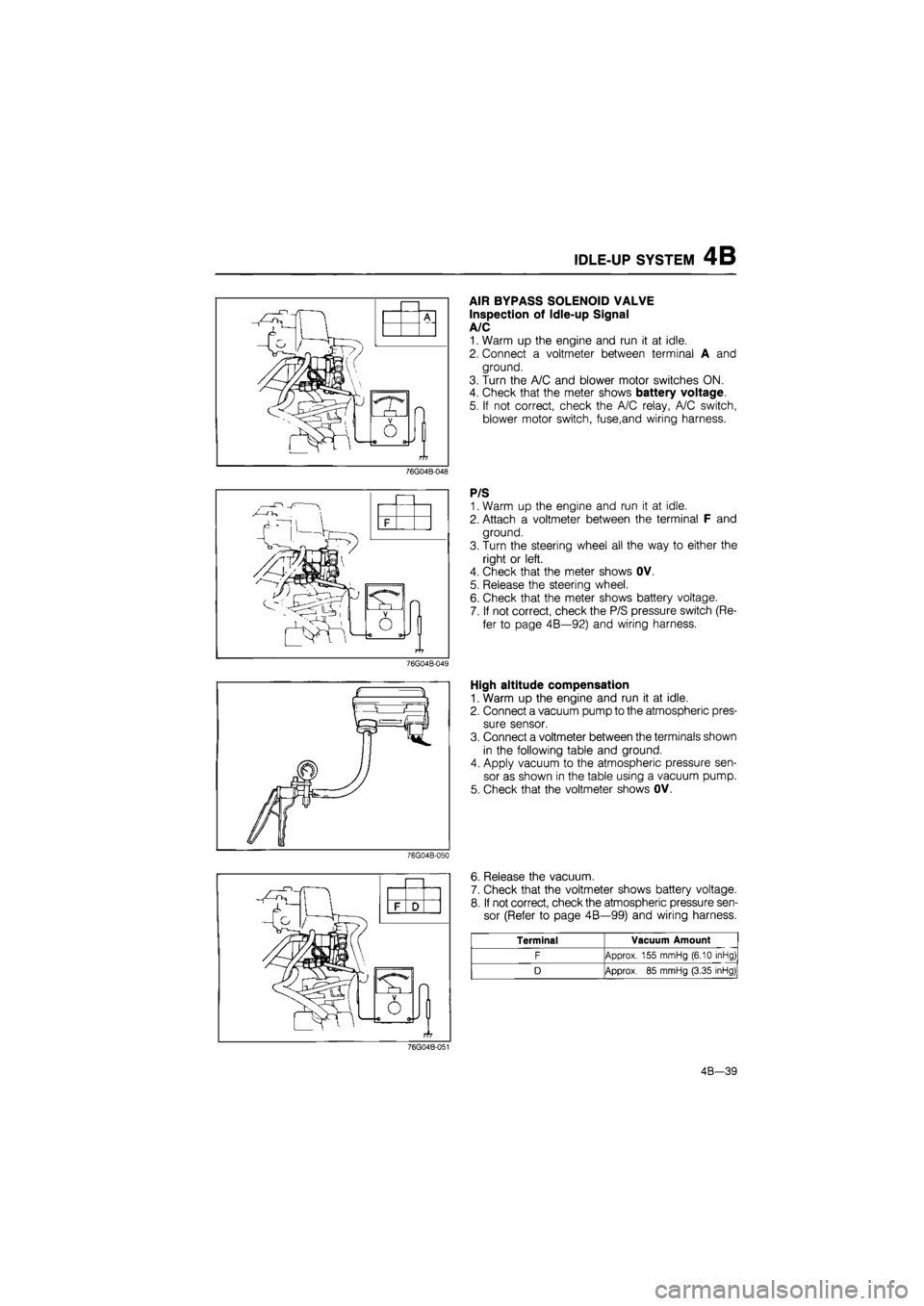
Inspection of Idle-up Signal
A/C
1. Warm up the engine and run it at idle.
2. Connect a voltmeter between terminal A and
ground.
3. Turn the A/C and blower motor switches ON.
4. Check that the meter shows battery voltage.
5. If not correct, check the A/C relay, A/C switch,
blower motor switch, fuse,and wiring harness.
76G04B-048
P/S
1. Warm up the engine and run it at idle.
2. Attach a voltmeter between the terminal F and
ground.
3. Turn the steering wheel all the way to either the
right or left.
4. Check that the meter shows OV.
5. Release the steering wheel.
6. Check that the meter shows battery voltage.
7. If not correct, check the P/S pressure switch (Re-
fer to page 4B—92) and wiring harness.
76G04B-049
High altitude compensation
1. Warm up the engine and run it at idle.
2. Connect a vacuum pump to the atmospheric pres-
sure sensor.
3. Connect a voltmeter between the terminals shown
in the following table and ground.
4. Apply vacuum to the atmospheric pressure sen-
sor as shown in the table using a vacuum pump.
5. Check that the voltmeter shows OV.
76G04B-050
J
O
6. Release the vacuum.
7. Check that the voltmeter shows battery voltage.
8. If not correct, check the atmospheric pressure sen-
sor (Refer to page 4B—99) and wiring harness.
Terminal Vacuum Amount
F Approx. 155 mmHg (6.10 inHg)
D Approx.
85
mmHg (3.35 inHg)
76G04B-051
4B-39
Page 549 of 1865

CONTROL SYSTEM 4B
ENGINE CONTROL UNIT
Engine Signal Monitor (49 9200 162) and Adapter (49 9200 163).
Adapter harness 49 9200 163
Engine wiring harnessN
Selector switch
Monitor switch
Engine control unit
terminal number
Terminals
(A and 8)
ENGINE SIGNAL MONITOR
86U04A-171
The Engine Signal Monitor (49 9200 162) was developed to check the control unit terminal voltages.
This monitor easily inspects the individual terminal voltages through selection of the monitor switch.
How to Use the Engine Signal Monitor
1. Connect the Engine Signal Monitor (49 9200 162) between the engine control unit and the en-
gine harness using the adapter (49 9200 163).
2. Turn the selector switch and monitor switch to select the terminal number.
3. Check the terminal voltage.
Caution
Never apply voltage to terminals A and B.
4B-87
Page 576 of 1865

TROUBLESHOOTING WITH SST 4C
Malfunction display
Sensor or subsystem Self-diagnosis Fail-safe Malfunction
code no. Malfunction code output signal pattern
Sensor or subsystem Self-diagnosis Fail-safe
08
Air flow sensor Open or short circuit Maintains basic sig-nal at preset value
09 o°pNp II IIL •
Water thermo sensor Open or short circuit Maintains constant 35°C (95°F) command
11 0°FNFJUUL
Intake air thermo sensor (dynamic chamber)
Short circuit Maintains constant 20°C (68°F) command
12
Throttle sensor Open or short circuit Maintains constant command of throttle valve fully open
15 ON n
OFF •L 01
Oxygen sensor Sensor output con-tinues less than 0.55V 120 sec. after engine starts (1,500 rpm or over)
Cancels
EG I
feed-
back operation
17 ON n
OFF L HI il
Feedback system Sensor output not changed 20 sec. af-ter engine starts (1,500 rpm or over)
Cancels
EG I
feed-
back operation
25 0°nfJU1LJIL
Solenoid valve (pres-sure regulator control)
Open or short circuit
26 2LMJIL
Solenoid valve (No.1 purge control)
Open or short circuit
27 ON nn
OFF | _ •111
-ii-Solenoid valve (No.2
purge control)
Open or short circuit
28 ON nn
OFF L Hi nr
Solenoid valve (EGR)
Open or short circuit
34 ^jmiHum
Solenoid valve (Idle speed control)
Open or short circuit
36 °FFJMI«U
Oxygen sensor relay
Open or short circuit
41 <£jimjiuM
Solenoid valve (Vari-able inertia control)
Open or short circuit
76G04C-018
Caution
a) If there is more than one failure present, the lowest number malfunction code is dis-
played first, the remaining codes are displayed sequentially.
b) After repairing a failure, turn off the ignition switch and disconnect the negative battery
cable and depress the brake pedal for at least 5 seconds to erase the memory of a mal-
function code.
4C—15
Page 606 of 1865

ISC SYSTEM 4C
COMPONENT DESCRIPTION
Component Function Remark
A/C switch Detects air conditioner operation; sends
signal to engine control unit Switch ON when air conditioner
operating
Air valve When cold, supplies bypass air into dy-namic chamber • Engine speed increased to shorten warm-up period • Thermo wax type
• Installed in BAC valve
Clutch switch Detects in-gear condition; sends signal to engine control unit Switch ON when clutch pedal released
E/L control unit Detects that E/L is being applied; sends
signal to engine control unit
Engine control unit Detects signals from input sensors and switches; controls solenoid valve (Idle speed control)
Idle switch Detects when throttle valve fully closed;
sends signal to engine control unit
Installed on throttle body
Ne signal pick-up Detects crank angle at 180° intervals; sends signal to engine control unit Installed in distributor
Neutral switch Detects in-gear condition; sends signal to engine control unit
Switch ON when in gear
P/S pressure switch Detects P/S operation; sends signal to engine control unit Switch ON when steering wheel turned right or left
Solenoid valve (Idle speed control) Controls bypass air amount • Controlled by duty signal from engine control unit • Installed in BAC valve
• Operates idle-up
Test connector For initial idle speed adjustment • Gerrn, 1-pin
• Idle speed feedback control cancelled when connector grounded
Water thermo sensor Detects coolant temperature; sends
signal to engine control unit
76G04C-078
4C—45
Page 659 of 1865

4C CONTROL SYSTEM
ENGINE CONTROL UNIT
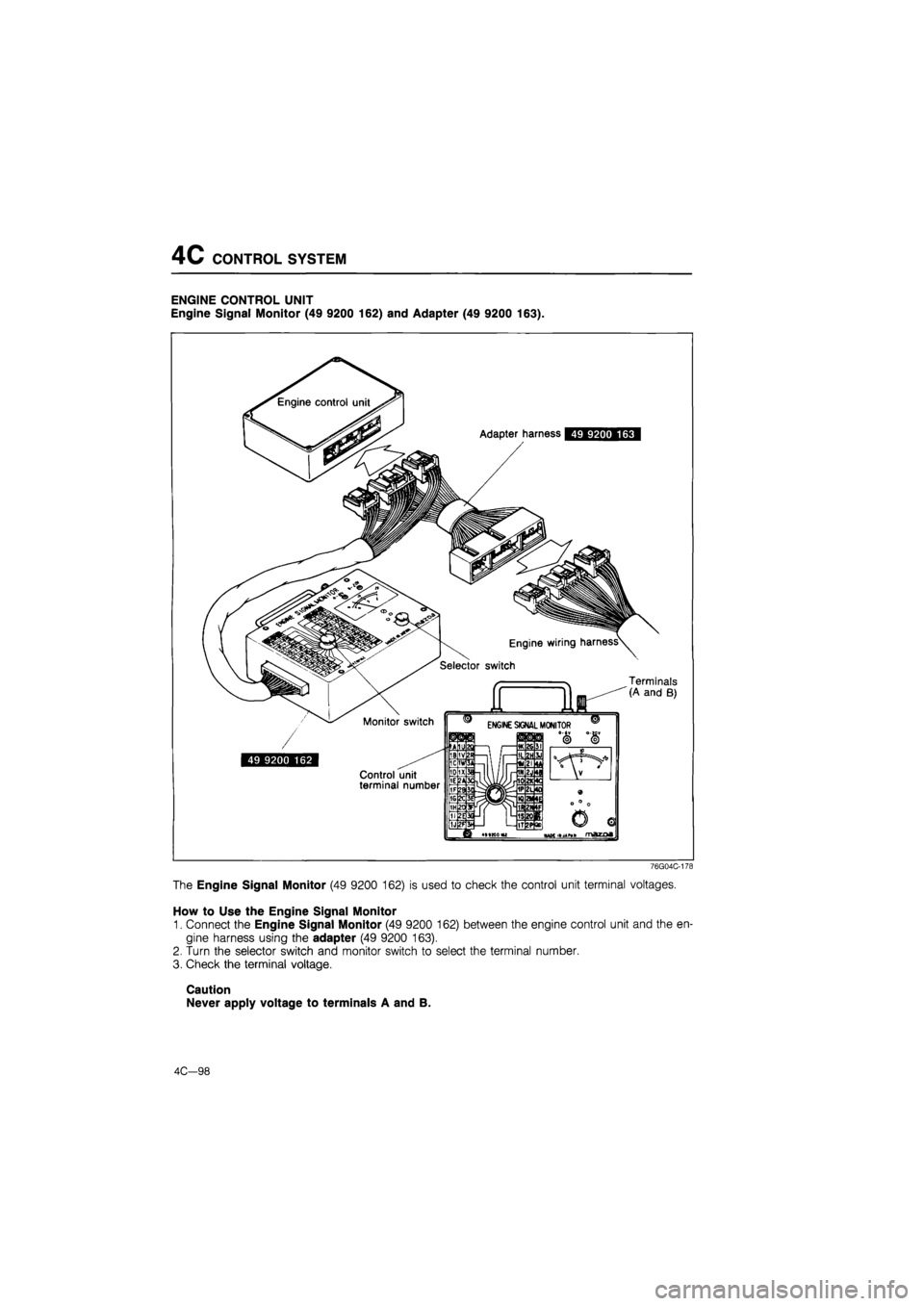
Engine Signal Monitor (49 9200 162) and Adapter (49 9200 163).
Adapter harness 49 9200 163
Engine wiring harness^
Selector switch
' —
Monitor switch
49 9200 162
Control unit terminal number
Terminals (A and B)
Q IIIM«I
76G04C-178
The Engine Signal Monitor (49 9200 162) is used to check the control unit terminal voltages.
How to Use the Engine Signal Monitor
1. Connect the Engine Signal Monitor (49 9200 162) between the engine control unit and the en-
gine harness using the adapter (49 9200 163).
2. Turn the selector switch and monitor switch to select the terminal number.
3. Check the terminal voltage.
Caution
Never apply voltage to terminals A and B.
4C—98