engine MAZDA 626 1987 Workshop Manual
[x] Cancel search | Manufacturer: MAZDA, Model Year: 1987, Model line: 626, Model: MAZDA 626 1987Pages: 1865, PDF Size: 94.35 MB
Page 1467 of 1865

ANTI-LOCK BRAKE SYSTEM (ABS) 1 1
Diagnosis Table
Note
Flashing of the warning light shows past failure, and its illumination shows present failure.
Diagnosis indication Possible failure Flow chart
No. Warning light Voltmeter Possible failure Flow chart
No.
ON
n
i2vn
OV
Hydraulic unit Harness
Right front wheel speed
sensor ABS-1
ON
n nn
Hydraulic unit Harness Left front wheel speed sensor ABS-2
OFF
Hydraulic unit Harness Left front wheel speed sensor ABS-2
OFF
nnn
Hydraulic unit Harness
Rear wheel speed sensor ABS-3
n
nnnn
Right front sensor rotor ABS-4
n
nnnnn
Left front sensor rotor ABS-5
JLilTUITLTL
Right rear sensor rotor ABS-6
jirLruiJum
Left rear sensor rotor ABS-7
J n
Hydraulic unit Harness
Control unit connector (11-pin)
ABS-8
nnnn
Hydraulic unit Harness
Control unit connector (11-pin)
ABS-8
J nn
Relay box
Hydraulic unit
Harness
ABS-9
jumruiTL
Relay box
Hydraulic unit
Harness
ABS-10
j nnn
Relay box
Hydraulic unit
Harness
ABS-11
jinnjuuL
Relay box
Hydraulic unit
Harness ABS-12
j nnnn
Relay box
Hydraulic unit
Harness
ABS-13
jiruuirirL
Relay box
Hydraulic unit
Harness
ABS-14
j nnnnn
Hydraulic unit Harness Control unit
ABS-15
juuuiruL
Hydraulic unit Harness Control unit ABS-16
j JinjiruifL.
Control unit
ABS-17
jiruinjiri—
JinjiruifL.
Control unit
ABS-18
j
No signal; failure condi-tions not stored
in
memory
Control unit Control unit connector (17-pin) Battery capacity Alternator output voltage Wiring harness (warning light-control unit-check connector)
Inspect, and repair or replace as necessary
j
No signal; failure condi-tions not stored
in
memory
No problem When warning light does
not
illuminate with engine running and
no
jumper wire
76G11X092
11-75
Page 1468 of 1865
1 1 ANTI-LOCK BRAKE SYSTEM (ABS)
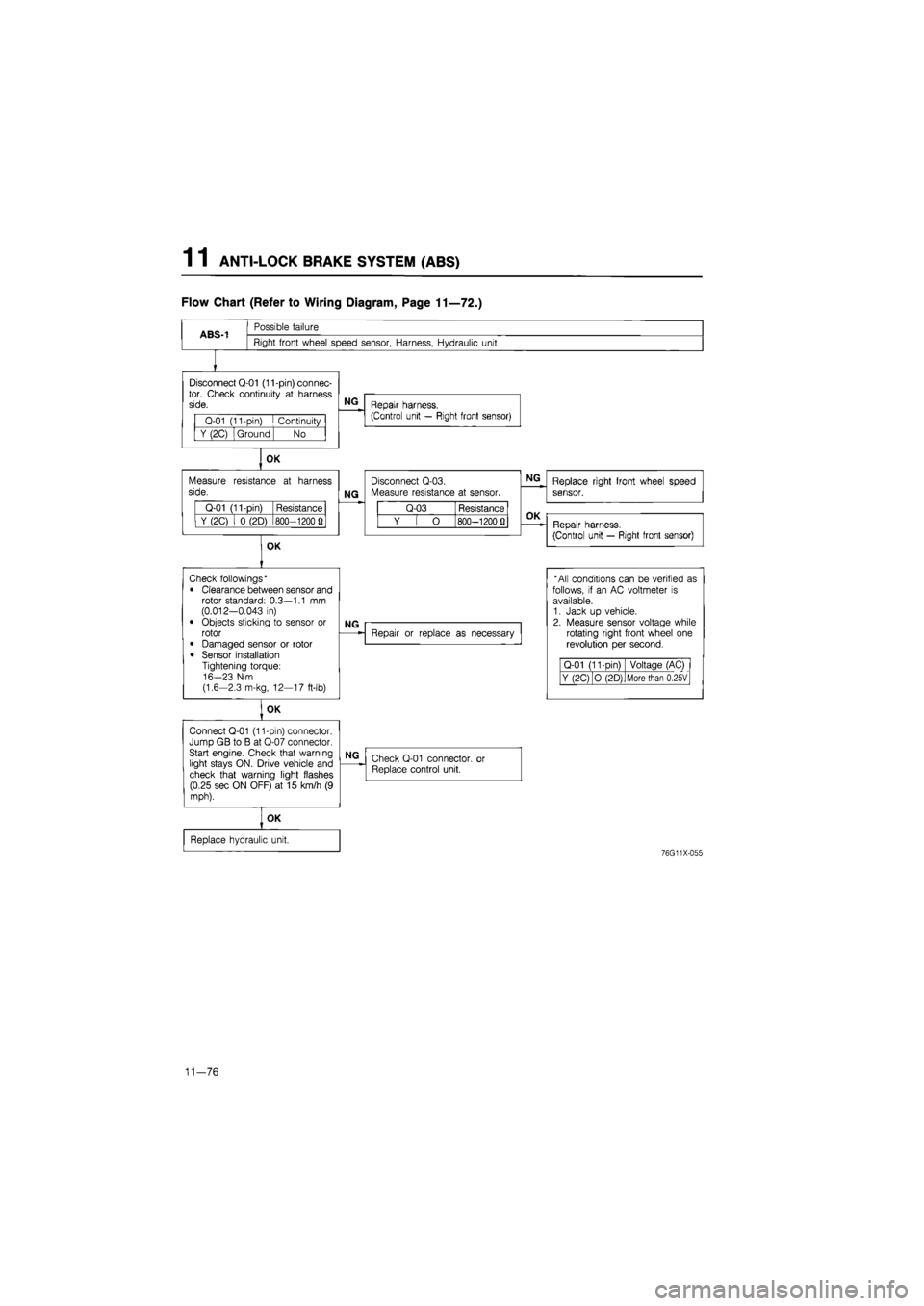
Flow Chart (Refer to Wiring Diagram, Page 11—72.)
ABS-1
Possible failure
Right front wheel speed sensor, Harness, Hydraulic unit
Disconnect Q-01 (11-pin) connec-tor. Check continuity
at
harness side.
Q-01 (11-pin)
I
Continuity
Y (2C) Ground No
OK
Measure resistance
at
harness side.
Q-01 (11-pin) Resistance
Y (2C)
i 0
(2D) 800—1200
Q
OK
NG
Repair harness.
(Control unit — Right front sensor)
NG
Disconnect Q-03. Measure resistance
at
sensor.
Q-03 Resistance
Y
[ O
800—1200 Q
NG
Replace right front wheel speed sensor.
OK
Repair harness.
(Control unit — Right front sensor)
Check followings*
• Clearance between sensor and rotor standard: 0.3—1.1
mm
(0.012-0.043
in)
• Objects sticking
to
sensor
or
rotor
• Damaged sensor
or
rotor
• Sensor installation Tightening torque: 16-23 N-m (1.6-2.3 m-kg, 12—17 ft-lb)
OK
Connect Q-01 (11-pin) connector. Jump GB
to B at
Q-07 connector. Start engine. Check that warning light stays ON. Drive vehicle and check that warning light flashes (0.25 sec ON OFF)
at 15
km/h
(9
mph).
NG
Repair
or
replace
as
necessary
* All conditions can
be
verified
as
follows,
if an AC
voltmeter
is
available. 1. Jack
up
vehicle. 2. Measure sensor voltage while rotating right front wheel
one
revolution
per
second.
Q-01 (11-Din) Voltage (AC)
Y (2C) O (2D) More than 0.25V
NG
Check Q-01 connector,
or
Replace control unit.
OK
Replace hydraulic unit.
76G11X-055
11—76
Page 1469 of 1865
ANTI-LOCK BRAKE SYSTEM (ABS) 1 1
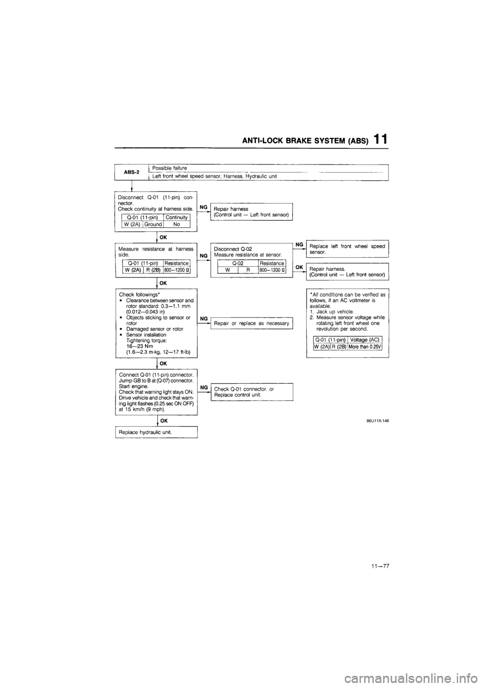
ABS-2
Possible failure
Left front wheel speed sensor, Harness, Hydraulic unit
Disconnect
Q-01
(11-pin)
con-
nector.
Check continuity
at
harness side.
Q-01 (11-pin) Continuity
W (2A) Ground No
OK
Measure side.
Q-01 (11-pin) Resistance
W (2A) R (2B) 800-1200
fl
OK
Connect Q-01 (11-pin) connector. Jump GB
to B
at (Q-07) connector. Start engine.
Check that warning light stays ON. Drive vehicle and check that warn-ing light flashes (0.25 sec ON OFF) at
15
km/h
(9
mph).
NG
Repair harness (Control unit
—
Left front sensor)
resistance
at
harness
NG
Disconnect Q-02 Measure resistance
at
sensor.
Q-02 Resistance
W
| R
800-1200
0
OK
Check followings*
• Clearance between sensor and rotor standard: 0.3—1.1
mm
(0.012-0.043
in)
• Objects sticking
to
sensor
or
rotor • Damaged sensor
or
rotor
• Sensor installation Tightening torque: 16-23 N m
(1.6—2.3 m-kg, 12-17 ft-lb)
NG
OK
NG
Repair
or
replace
as
necessary
NG
Check Q-01 connector,
or
Replace control unit.
OK
Replace hydraulic unit.
Replace left front wheel speed
sensor.
Repair harness.
(Control unit
—
Left front sensor)
"All conditions can
be
verified
as
follows,
if an AC
voltmeter
is
available. 1. Jack
up
vehicle. 2. Measure sensor voltage while rotating left front wheel
one
revolution
per
second.
Q-01 (11-pin) Voltage (AC)
W (2 A)
|
R (2B) More than
0
25V
86U11X-146
11-77
Page 1470 of 1865
1 1 ANTI-LOCK BRAKE SYSTEM (ABS)
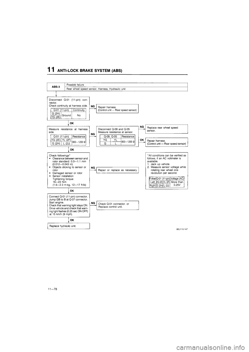
ABS-3
Possible failure
Rear wheel speed sensor, Harness, Hydraulic unit
Disconnect
Q-01
(11-pin)
con-
nector.
Check continuity
at
harness side.
Q-01 (11-pin) Continuity
G (2H) Ground No YG (2E) Ground No
Measure side.
Q-01 (11-pin) Resistance
YG (2E) YL (2F) 800—1200
fi
G (2H)
] L
(2J) 800—1200
fi
OK
Connect Q-01 (11-pin) connector. Jump GB
to B at
Q-07 connector. Start engine.
Check that warning light stays ON. Drive vehicle and check that warn-ing light flashes (0.25 sec ON OFF) at
15
km/h
(9
mph).
NG
Repair harness (Control unit
—
Rear speed sensor)
OK
resistance
at
harness
NG
Disconnect Q-09 and Q-05 Measure resistance
at
sensor.
Q-09, Q-05 Resistance
YG YL 800-1200
0
G L 800-1200
0
OK
Check followings* • Clearance between sensor and rotor standard: 0.3—1.1
mm
(0.012-0.043
in)
• Objects sticking
to
sensor
or
rotor
• Damaged sensor
or
rotor
• Sensor installation Tightening torque: 16-23 N-m
(1.6—2.3 m-kg, 12—17 ft-lb)
NG
Repair
or
replace
as
necessary
NG
Check Q-01 connector. Replace control unit.
or
OK
Replace hydraulic unit,
Replace rear wheel speed
sensor.
OK
Repair harness.
(Control unit
—
Rear speed sensor)
* All conditions can
be
verified
as
follows,
if an AC
voltmeter
is
available. 1. Jack
up
vehicle. 2. Measure sensor voltage while rotating rear wheel
one
revolution
per
second.
fi
wheel Q-01 (11-pin) Voltaqe (AC)
Left |YG (2E) YL (2F) More than 0.25V Right G (2H) L(2J)
More than 0.25V
86U11X-147
11-78
Page 1472 of 1865
1 1 ANTI-LOCK BRAKE SYSTEM (ABS)
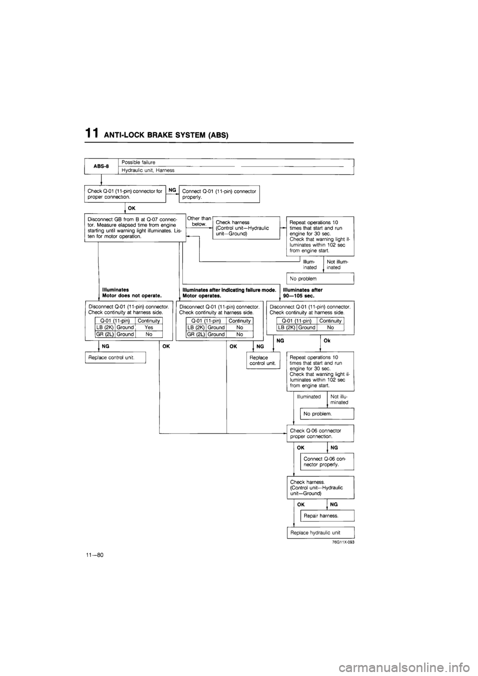
ABS-8
Possible failure
ABS-8
Hydraulic unit, Harness
Check Q-01 (11-pin) connector for
proper connection.
NG
Connect Q-01 (11-pin) connector
properly.
OK
Disconnect
GB
from
B at
Q-07 connec-tor. Measure elapsed time from engine starting until warning light illuminates.
Lis-
ten
for
motor operation.
Other than
below. Check harness (Control unit—Hydraulic unit—Ground)
Repeat operations
10
times that start and
run
engine
for 30
sec. Check that warning light
i
luminates within 102 sec from engine start.
Illum-
inated
Not illum-inated
No problem
Illuminates Motor does not operate.
Disconnect Q-01 (11-pin) connector.
Check continuity
at
harness side.
Q-01 (11-pin) Continuity
LB (2K) Ground Yes
GR (2L) Ground
| No
NG
Replace control unit.
OK
Illuminates after indicating failure mode.
Motor operates.
Disconnect Q-01 (11-pin) connector. Check continuity
at
harness side.
Q-01 (11-pin) Continuity
LB (2K) Ground No
GR (2L) Ground No
OK
Illuminates after
90—105 sec.
Disconnect Q-01 (11-pin) connector.
Check continuity
at
harness side.
Q-01 (11-pin) Continuity
LB (2K) Ground No
NG
NG
Replace control unit.
Ok
Repeat operations
10
times that start and
run
engine
for 30
sec. Check that warning light
il-
luminates within 102 sec from engine start.
Illuminated Not illu-
minated
No problem.
Check Q-06 connector proper connection.
76G11X-093
11-80
Page 1478 of 1865
1 1 ANTI-LOCK BRAKE SYSTEM (ABS)
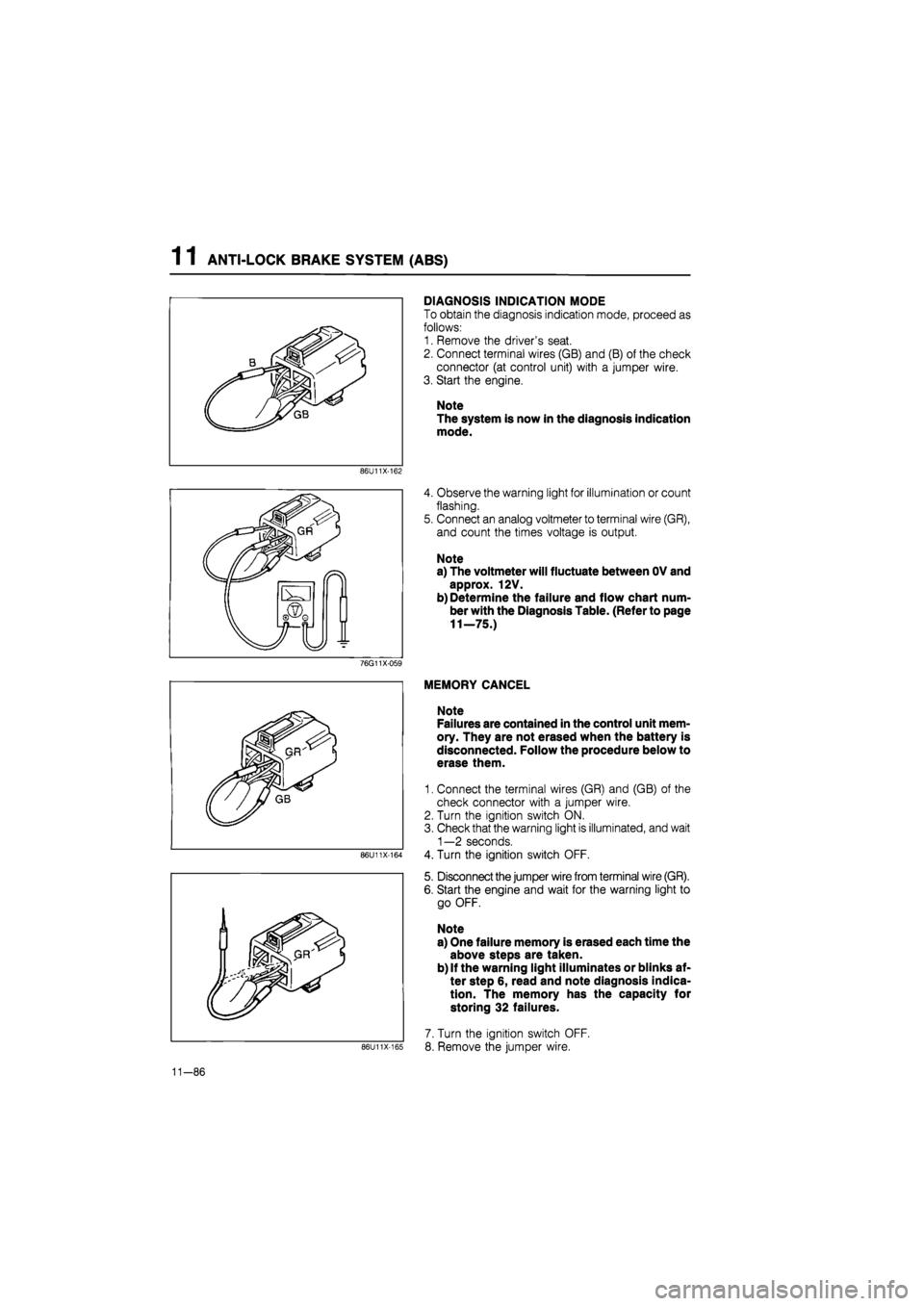
DIAGNOSIS INDICATION MODE
To obtain the diagnosis indication mode, proceed as
follows:
1. Remove the driver's seat.
2. Connect terminal wires (GB) and (B) of the check
connector (at control unit) with a jumper wire.
3. Start the engine.
Note
The system is now in the diagnosis indication
mode.
86U11X-162
4. Observe the warning light for illumination or count
flashing.
5. Connect an analog voltmeter to terminal wire (GR),
and count the times voltage is output.
Note
a) The voltmeter will fluctuate between OV and
approx. 12V.
b) Determine the failure and flow chart num-
ber with the Diagnosis Table. (Refer to page
11—75.)
76G11X-059
86U11X-164
86U11X-165
MEMORY CANCEL
Note
Failures are contained in the control unit mem-
ory. They are not erased when the battery is
disconnected. Follow the procedure below to
erase them.
1. Connect the terminal wires (GR) and (GB) of the
check connector with a jumper wire.
2. Turn the ignition switch ON.
3. Check that the warning light is illuminated, and wait
1—2 seconds.
4. Turn the ignition switch OFF.
5. Disconnect the jumper wire from terminal wire (GR).
6. Start the engine and wait for the warning light to
go OFF.
Note
a) One failure memory is erased each time the
above steps are taken.
b) If the warning light illuminates or blinks af-
ter step 6, read and note diagnosis indica-
tion. The memory has the capacity for
storing 32 failures.
7. Turn the ignition switch OFF.
8. Remove the jumper wire.
11-86
Page 1486 of 1865

1 1 ANTI-LOCK BRAKE SYSTEM (ABS)
HYDRAULIC UNIT FLUID
Inspection of Level
1. Run the engine for 10 seconds to let the pump mo-
tor build pressure in the accumulator; then stop the
engine.
2. Check that the fluid level is between the Max and
Min lines of the reservoir.
3. If the level is lower than the Min line and leakage
from cap is not found, replace the hydraulic unit
assembly.
86U11X-187
76G11X-061
Replacement
1. Remove the reservoir cap and retainer.
2. Use a suction pump and a soft vinyl hose to suck
fluid from the reservoir.
Caution
a) A hard hose may damage the filter in the
reservoir.
b)Only the amount of fluid shown can be re-
moved from the reservoir.
3. Fill the reservoir with the specified type and amount
of brake fluid.
Caution
a) Do not allow any foreign material to enter
the reservoir.
b) Do not soak the upper filter with brake flu-
id. Otherwise, pouring fluid may be difficult.
Fluid: DOT-3 or DOT-4 or SAE J1703
4. Check the fluid level as described above.
HYDRAULIC UNIT
Warning
The accumulator contains high-pressure gas;
do not attempt to disassemble it or subject it
to hard shocks or high heat.
When the hydraulic unit is scrapped, the high-
pressure gas must be released. Turn the
screw on the accumulator bottom one full turn
only and allow the gas to escape gradually.
76G11X-097
11—94
Page 1487 of 1865
ANTI-LOCK BRAKE SYSTEM (ABS) 1 1
86U11X-190
86U11X-191
76G11X098
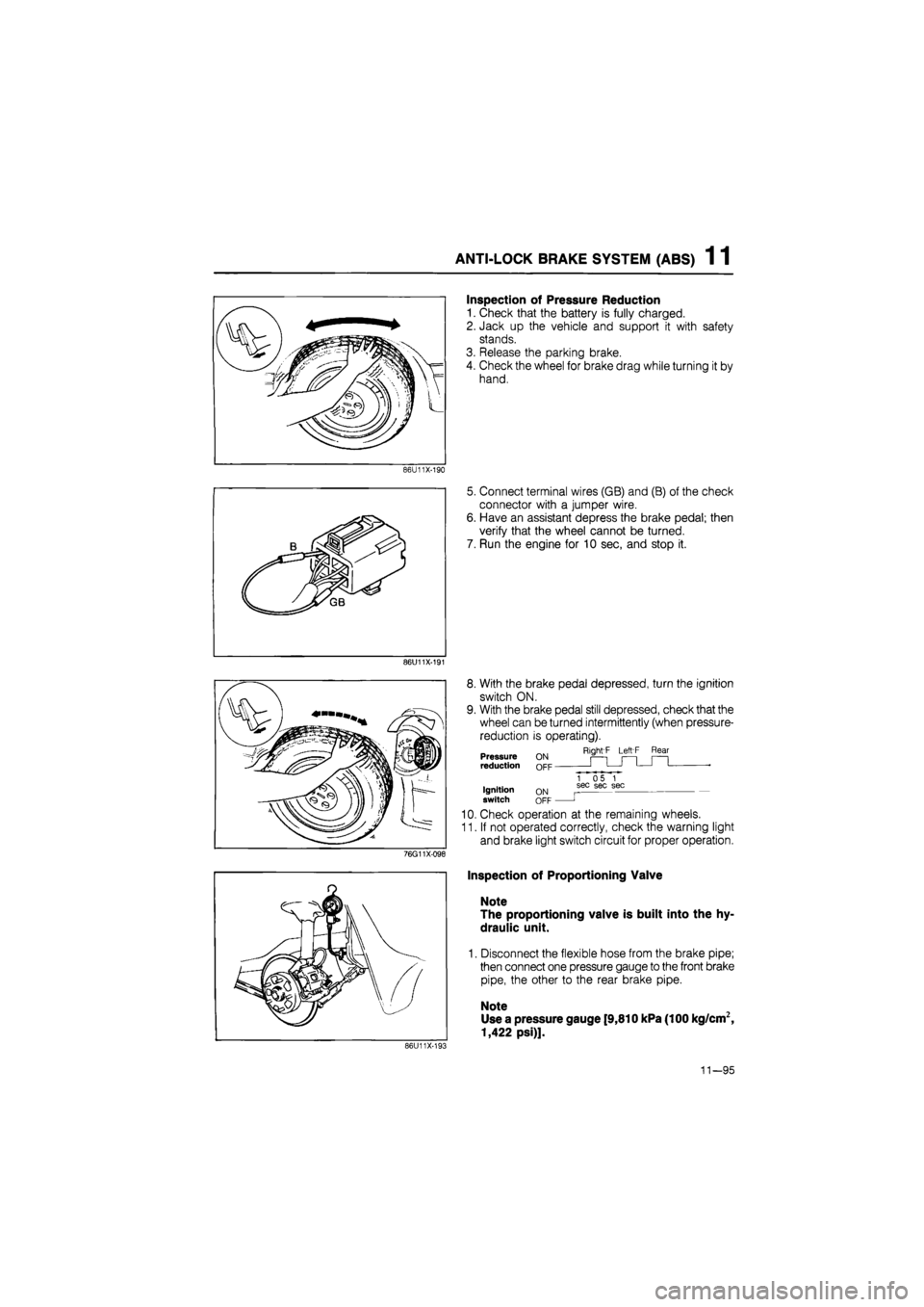
Inspection of Pressure Reduction
1. Check that the battery is fully charged.
2. Jack up the vehicle and support it with safety
stands.
3. Release the parking brake.
4. Check the wheel for brake drag while turning it by
hand.
5. Connect terminal wires (GB) and (B) of the check
connector with a jumper wire.
6. Have an assistant depress the brake pedal; then
verify that the wheel cannot be turned.
7. Run the engine for 10 sec, and stop it.
8. With the brake pedal depressed, turn the ignition
switch ON.
9. With the brake pedal still depressed, check that the
wheel can be turned intermittently (when pressure-
reduction is operating).
Right'F Left F Rear Pressure reduction
Ignition switch ON OFF
1 05 1 sec sec sec
J
10. Check operation at the remaining wheels.
11. If not operated correctly, check the warning light
and brake light switch circuit for proper operation.
Inspection of Proportioning Valve
Note
The proportioning valve is built into the hy-
draulic unit.
1. Disconnect the flexible hose from the brake pipe;
then connect one pressure gauge to the front brake
pipe, the other to the rear brake pipe.
Note
Use a pressure gauge [9,810 kPa (100 kg/cm2,
1,422 psi)].
86U11X-193
11—95
Page 1488 of 1865

1 1 ANTI-LOCK BRAKE SYSTEM (ABS)
t
2. Bleed air from the system.
3. Depress the brake pedal, and compare the fluid
pressure of the front brake with that of the rear
brake.
Fluid pressure kPa (kg/cm2, psi)
Front brake side Rear brake side
A 2,943 (30,427)
A'
2,747-3,139
(28-32, 398-455)
A B
B 6,867 (70,995)
B'
3,924-4,316 (40-44, 569-626)
Front brake pressure kPa (kg/cm2, psi) 4. If the measurement is not within specification re-
place the hydraulic unit assembly. 86U11X-194
REMOVAL
Caution
a) Brake fluid will damage painted surfaces. If it does get on the painted surfaces, wipe
it off immediately.
b) Oo not tip the hydraulic unit to prevent the brake fluid in the reservoir from draining.
1. Remove the nuts mounting the fuel filter and ignitor to the bracket and move them toward the engine.
2. Remove the air cleaner assembly.
3. Remove the master cylinder. (Refer to page 11—14.)
4. Remove the hydraulic unit in the sequence shown in the figure.
76G11X-062
11—96
Page 1491 of 1865
ANTI-LOCK BRAKE SYSTEM (ABS) 1 1
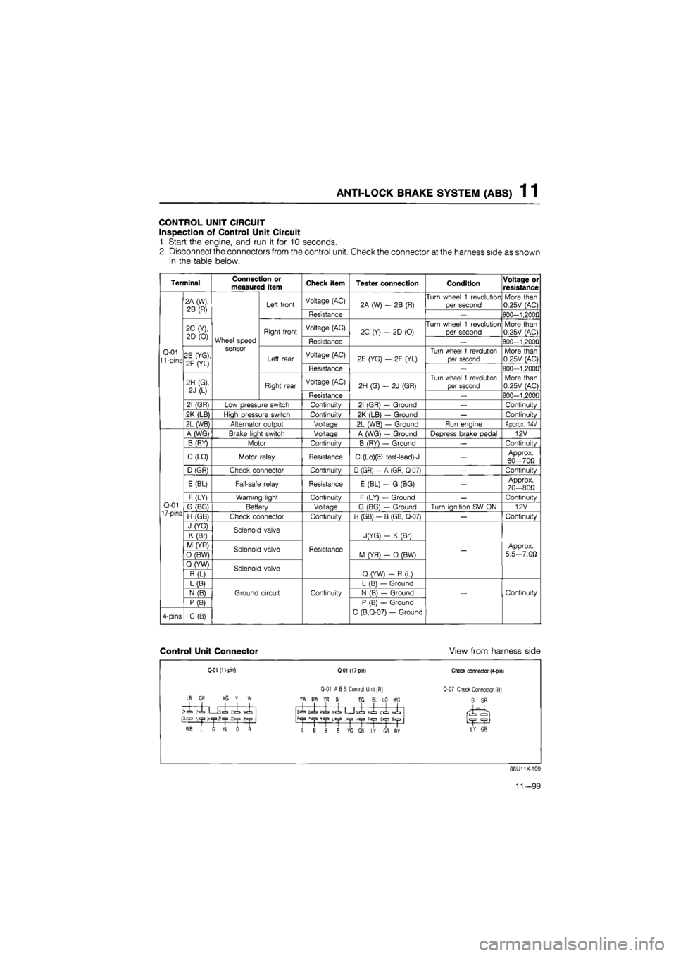
CONTROL UNIT CIRCUIT
Inspection of Control Unit Circuit
1. Start the engine, and run it for 10 seconds.
2. Disconnect the connectors from the control unit. Check the connector at the harness side as shown
in the table below.
Terminal Connection or measured item Check item Tester connection Condition Voltage or
resistance
Q-01 11 -pins
2A (W),
2B (R)
Wheel speed sensor
Left front Voltage (AC) 2A (W)
- 2B
(R) Turn wheel
1
revolution
per second More than 0.25V (AC)
Q-01 11 -pins
2A (W),
2B (R)
Wheel speed sensor
Left front
Resistance
2A (W)
- 2B
(R)
—
800-1.2000
Q-01 11 -pins
2C (Y),
2D
(0)
Wheel speed sensor
Right front Voltage (AC) 2C (Y)
-
2D (0) Turn wheel
1
revolution
per second More than 0.25V (AC)
Q-01 11 -pins
2C (Y),
2D
(0)
Wheel speed sensor
Right front
Resistance
2C (Y)
-
2D (0)
—
800-1,2000
Q-01 11 -pins 2E (YG),
2F (YL)
Wheel speed sensor
Left rear Voltage (AC) 2E (YG)
- 2F
(YL) Turn wheel
1
revolution
per second More than 0.25V (AC) Q-01 11 -pins 2E (YG),
2F (YL)
Wheel speed sensor
Left rear
Resistance
2E (YG)
- 2F
(YL)
—
800-1,200G
Q-01 11 -pins
2H (G).
2J
(L)
Wheel speed sensor
Right rear Voltage (AC) 2H (G)
- 2J
(GR)
Turn wheel
1
revolution
per second More than 0.25V (AC)
Q-01 11 -pins
2H (G).
2J
(L)
Wheel speed sensor
Right rear
Resistance
2H (G)
- 2J
(GR)
_
800-1,200fl
Q-01 11 -pins
21 (GR) Low pressure switch Continuity 21 (GR)
-
Ground
—
Continuity
Q-01 11 -pins
2K (LB) High pressure switch Continuity 2K (LB)
-
Ground
—
Continuity
Q-01 11 -pins
2L (WB) Alternator output Voltage 2L (WB)
-
Ground Run engine Approx.
14V
Q-01
17-pins
A (WG) Brake light switch Voltage A (WG)
-
Ground Depress brake pedal 12V
Q-01
17-pins
B (RY) Motor Continuity B (RY)
—
Ground
—
Continuity
Q-01
17-pins
C (LO) Motor relay Resistance C (Lo)(© test-lead)-J
—
Approx. 60—700
Q-01
17-pins
D (GR) Check connector Continuity D (GR)
- A
(GR, Q-07)
—
Continuity
Q-01
17-pins
E (BL) Fail-safe relay Resistance E (BL)
- G
(BG)
—
Approx. 70-800
Q-01
17-pins
F (LY) Warning light Continuity F (LY)
-
Ground
—
Continuitv Q-01
17-pins G (BG) Battery Voltage G (BG)
—
Ground Turn ianition
SW ON
12V Q-01
17-pins H (GB) Check connector Continuitv H (GB)
- B
(GB. Q-07)
—
Continuitv
Q-01
17-pins
J (YG) Solenoid valve
Resistance
JfYG)
- K
(Br)
-
Approx.
5.5—7.00
Q-01
17-pins
K (Br) Solenoid valve
Resistance
JfYG)
- K
(Br)
-
Approx.
5.5—7.00
Q-01
17-pins
M (YR) Solenoid valve Resistance M (YR)
- 0
(BW)
-
Approx.
5.5—7.00
Q-01
17-pins
0 (BW) Solenoid valve Resistance M (YR)
- 0
(BW)
-
Approx.
5.5—7.00
Q-01
17-pins
Q (YW) Solenoid valve
Resistance
Q (YW)
- R
(L)
-
Approx.
5.5—7.00
Q-01
17-pins
R (L) Solenoid valve
Resistance
Q (YW)
- R
(L)
-
Approx.
5.5—7.00
Q-01
17-pins
L (B)
Ground circuit Continuity
L (B)
—
Ground
Continuity
Q-01
17-pins
N
(B)
Ground circuit Continuity N (B)
—
Ground Continuity
Q-01
17-pins
P (B)
Ground circuit Continuity
P (B)
—
Ground
C (B.Q-07)
-
Ground
Continuity
4-pins C(B)
Ground circuit Continuity
P (B)
—
Ground
C (B.Q-07)
-
Ground
Continuity
Control Unit Connector View from harness side
Q-01 (11-pin)
LB
GR YG Y W
>1 ,1 U;.l Ki -X
1 L G VL rf
Q-01 (17-pin)
Q-01 ABS Control Unit [R]
YW BW YR Br 8G BL LO WG
icL olL
MIL
ICL G(=L tl ij^" llyl
>1
CjJ
Lt|J JCjJ fiC|3 H«|3
L B B B ffi SB L* GS RY
Check connector (4-pin)
Q-07 Check Connector [RJ
B GR
LY GB
86U11X-199
11—99