engine MAZDA 626 1987 Workshop Manual
[x] Cancel search | Manufacturer: MAZDA, Model Year: 1987, Model line: 626, Model: MAZDA 626 1987Pages: 1865, PDF Size: 94.35 MB
Page 1683 of 1865
15 METER
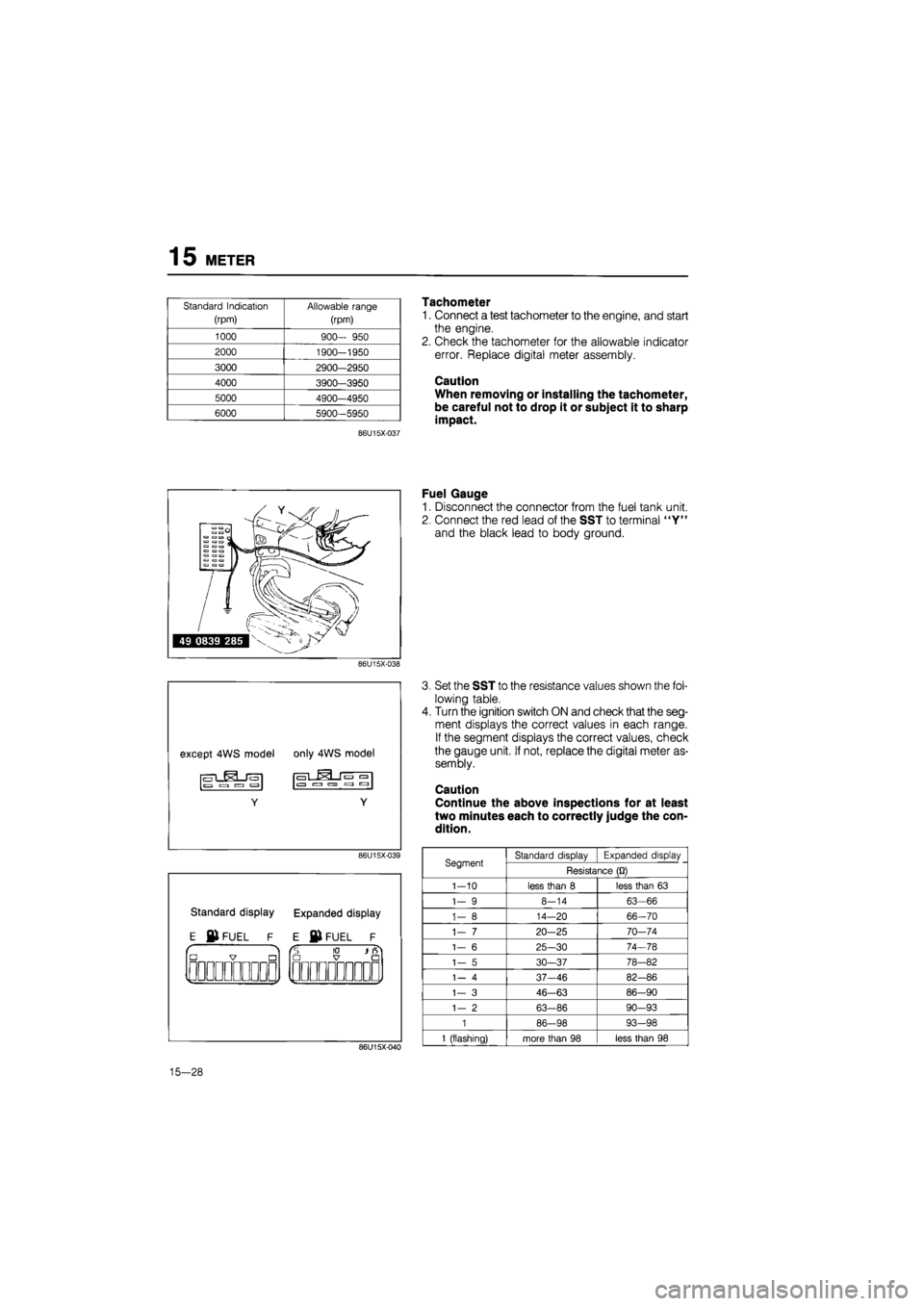
Standard Indication
(rpm)
Allowable range
(rpm)
1000
900—
950
2000 1900-1950
3000 2900—2950
4000 3900-3950
5000 4900—4950
6000 5900-5950
86U15X-037
86U15X-038
86U15X-039
Standard display Expanded display
E ©FUEL F E © FUEL F
"io — •
QJ1QOOODDOOOD
Tachometer
1. Connect a test tachometer to the engine, and start
the engine.
2. Check the tachometer for the allowable indicator
error. Replace digital meter assembly.
Caution
When removing or installing the tachometer,
be careful not to drop it or subject it to sharp
impact.
Fuel Gauge
1. Disconnect the connector from the fuel tank unit.
2. Connect the red lead of the SST to terminal "Y"
and the black lead to body ground.
86U15X-040
Set the SST to the resistance values shown the fol-
lowing table.
Turn the ignition switch ON and check that the seg-
ment displays the correct values in each range.
If the segment displays the correct values, check
the gauge unit. If not, replace the digital meter as-
sembly.
Caution
Continue the above inspections for at least
two minutes each to correctly judge the con-
dition.
Segment Standard display Expanded display Segment Resistance
(Q)
1-10
less than
8
less than
63
1-
9
8-14
63-66
1-
8
14—20 66-70
1-
7
20-25 70-74
1-
6
25-30 74-78
1-
5
30—37 78-82
1-
4
37-46 82-86
1—
3
46-63 86-90
1-
2
63-86 90-93
1
86-98 93-98
1
(flashing) more than
98
less than
98
15-28
Page 1690 of 1865
WARNING LIGHT AND SENDER 1 5
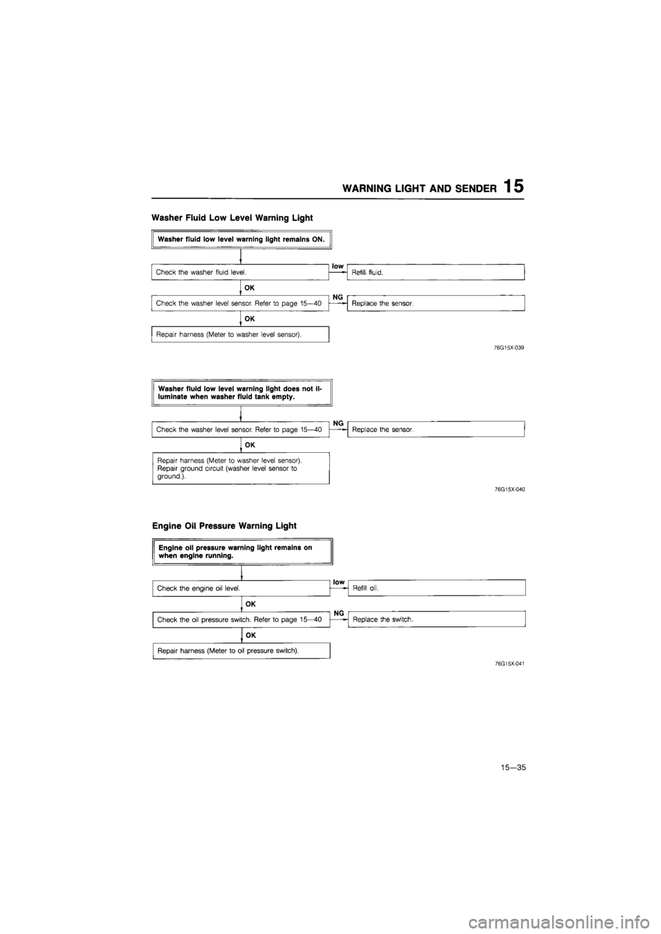
Washer Fluid Low Level Warning Light
76G15X-039
76G15X-040
Engine Oil Pressure Warning Light
76G15X-041
15—35
Page 1695 of 1865
15 WARNING AND SENDER
86U15X-068
86U15X069
86U15X-070
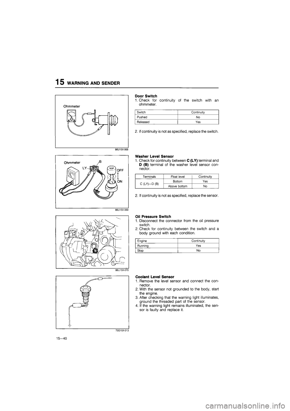
Door Switch
1. Check for continuity of the switch with an
ohmmeter.
2. If continuity is not as specified, replace the switch.
Washer Level Sensor
1. Check for continuity between C (LY) terminal and
D (B) terminal of the washer level sensor con-
nector.
Oil Pressure Switch
1. Disconnect the connector from the oil pressure
switch.
2. Check for continuity between the switch and a
body ground with each condition.
Coolant Level Sensor
1. Remove the level sensor and connect the con-
nector.
2. With the sensor not grounded to the body, start
the engine.
3. After checking that the warning light illuminates,
ground the threaded part of the sensor.
4. If the warning light remains illuminated, the sen-
sor is faulty and replace it.
73G15X-013
15—40
Engine Continuity
Running Yes
Stop No
Terminals Float level Continuity
C (LY)—D
(B)
Bottom Yes C (LY)—D
(B)
Above bottom No
2. If continuity is not as specified, replace the sensor.
Page 1697 of 1865
1 5 CENTRAL PROCESSING UNIT (CPU)
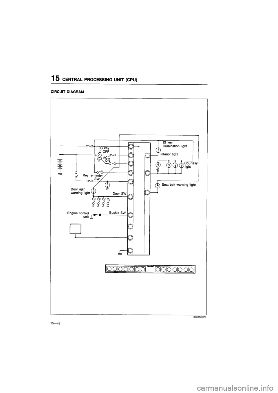
CIRCUIT DIAGRAM
-O-vO
I &
IG key
OFF
n\ Key reminder
Door ajar
warning light vf Door SW
llfl Engine control —_
unitj^"
Buckle SW
W7i
0
o
o
0
o
0
o
o
o
a
Q
u
n
dD
IG key
illumination light
[ Interior light
(f)
(f) (|)
teesy
J
cF Seat belt warning light
o o o 0 o o o
•a-
o o o o o o o
15-42
86U15X-073
Page 1740 of 1865
CRUISE CONTROL SYSTEM 1 5
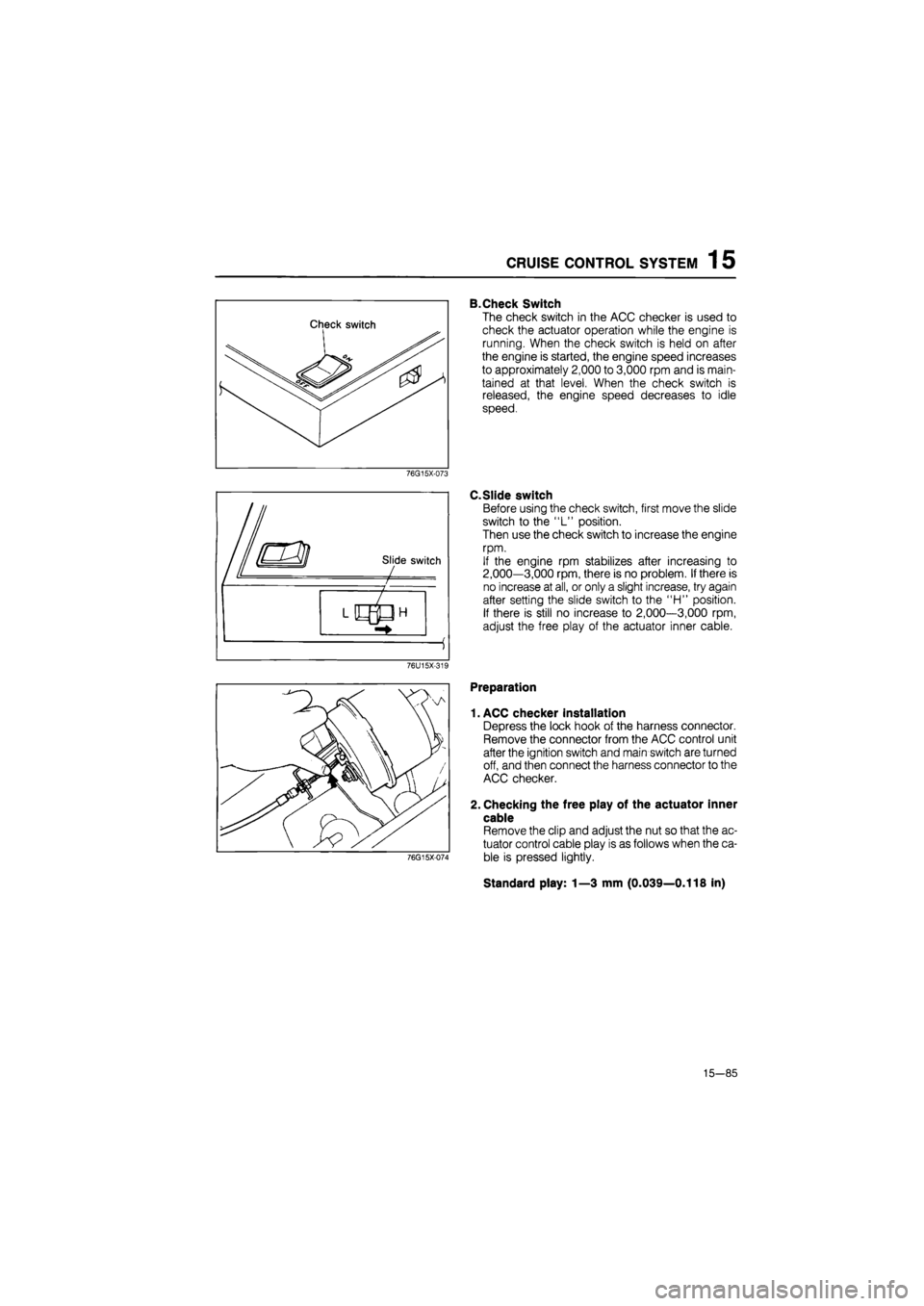
B.Check Switch
The check switch in the ACC checker is used to
check the actuator operation while the engine is
running. When the check switch is held on after
the engine is started, the engine speed increases
to approximately 2,000 to 3,000 rpm and is main-
tained at that level. When the check switch is
released, the engine speed decreases to idle
speed.
76G15X-073
C.Slide switch
Before using the check switch, first move the slide
switch to the "L" position.
Then use the check switch to increase the engine
rpm.
If the engine rpm stabilizes after increasing to
2,000—3,000 rpm, there is no problem. If there is
no increase at all, or only a slight increase, try again
after setting the slide switch to the "H" position.
If there is still no increase to 2,000—3,000 rpm,
adjust the free play of the actuator inner cable.
76U15X-319
76G15X-074
Preparation
1. ACC checker installation
Depress the lock hook of the harness connector.
Remove the connector from the ACC control unit
after the ignition switch and main switch are turned
off, and then connect the harness connector to the
ACC checker.
2. Checking the free play of the actuator inner
cable
Remove the clip and adjust the nut so that the ac-
tuator control cable play is as follows when the ca-
ble is pressed lightly.
Standard play: 1—3 mm (0.039—0.118 in)
15—85
Page 1742 of 1865
CRUISE CONTROL SYSTEM 1 5
CHECK LIGHTS (correct response)
ACTUATOR £
5 (O
W X
CHECK ITEMS AND CONDITIONS £ <0 z
VAC
CM I-1-z
Ul * < IE ffl X o V-
z o F < z ta
DC O 1-< DC Ui
TROUBLESHOOTING
(INCORRECT RESPONSE)
< S VAC UJ > < > -1 o o o UJ O
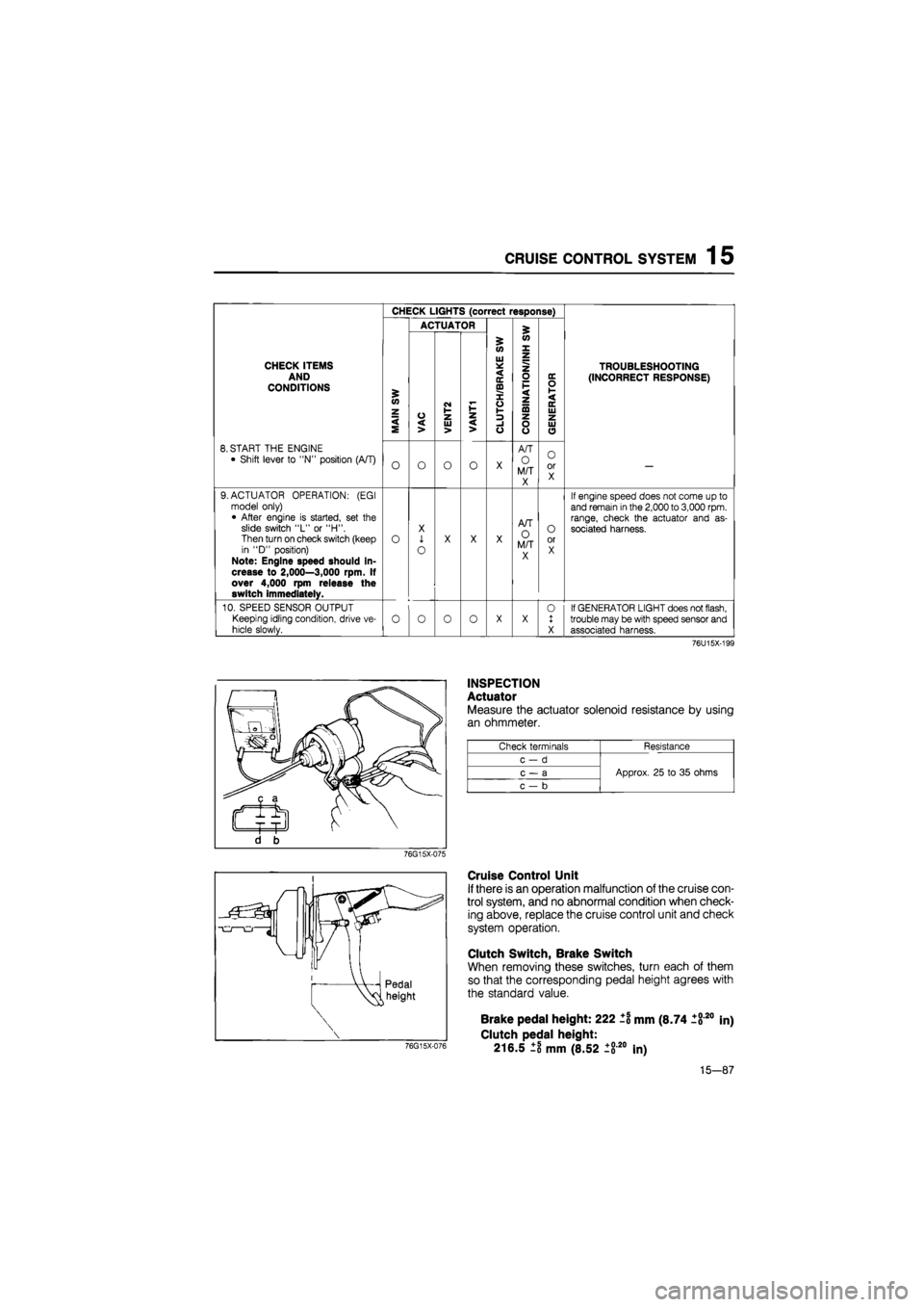
8. START THE ENGINE
• Shift lever to "N" position (A/T) O O O o X
A/T
O M/T X
O or X —
9. ACTUATOR OPERATION: (EGI model only) • After engine is started, set the slide switch "L" or "H". Then turn on check switch (keep in "D" position) Note: Engine speed should in-crease to 2,000—3,000 rpm. If over 4,000 rpm release the switch immediately.
o
X
1
o
X X X
A/T O M/T X
O or X
If engine speed does not come up to and remain
in
the
2,000
to
3,000
rpm. range, check the actuator and as-sociated harness.
10. SPEED SENSOR OUTPUT
Keeping idling condition, drive ve-
hicle slowly. o o 0 o X X 0 1 X
If GENERATOR LIGHT does not flash, trouble may be with speed sensor and associated harness.
76U15X-199
INSPECTION
Actuator
Measure the actuator solenoid resistance by using
an ohmmeter.
Check terminals Resistance
c-d
Approx. 25 to 35 ohms c — a Approx. 25 to 35 ohms
c — b
Approx. 25 to 35 ohms
76G15X-075
Cruise Control Unit
If there is an operation malfunction of the cruise con-
trol system, and no abnormal condition when check-
ing above, replace the cruise control unit and check
system operation.
Clutch Switch, Brake Switch
When removing these switches, turn each of them
so that the corresponding pedal height agrees with
the standard value.
76G15X-076
Brake pedal height: 222 ±1 mm (8.74 1820
Clutch pedal height:
216.5 ±8 mm (8.52 ±820 In)
in)
15-87
Page 1749 of 1865
1 5 AUTO ADJUSTING SUSPENSION (AAS)
AUTO ADJUSTING SUSPENSION (AAS)
CIRCUIT DIAGRAM
Combination switch iq Speed sensor
M
Panel light
control
AAS control unit
Steering angle sensor
H
N
Check connector
IG IG
Actuator (RR)
-P-Sl
-t-^J
—Pwsl
Actuator (RL)
Actuator (FR) P5fl
+
Actuator (FL)
QO M K GIE C A
ft N J HI F D B
86U15X-151
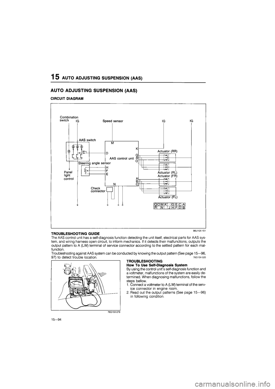
TROUBLESHOOTING GUIDE
The AAS control unit has a self-diagnosis function detecting the unit itself, electrical parts for AAS sys-
tem, and wiring harness open circuit, to inform mechanics. If it detects their malfunctions, outputs the
output pattern to A (LW) terminal of service connector according to the settled pattern for each mal-
function.
Troubleshooting against AAS system can be conducted by knowing the output pattern (See page 15—96,
97) to detect trouble location. 76gisx-o2o
TROUBLESHOOTING
How To Use Self-Diagnosis System
By using the control unit's self-diagnosis function and
a voltmeter, malfunctions of the system are easily de-
termined. When diagnosing malfunctions, follow the
steps bellow.
1. Connect a voltmeter to A (LW) terminal of the serv-
ice connector in engine room.
2. Read out the output patterns (See page 15—96)
in following condition.
76G15X-079
15—94
Page 1788 of 1865
OUTLINE 16
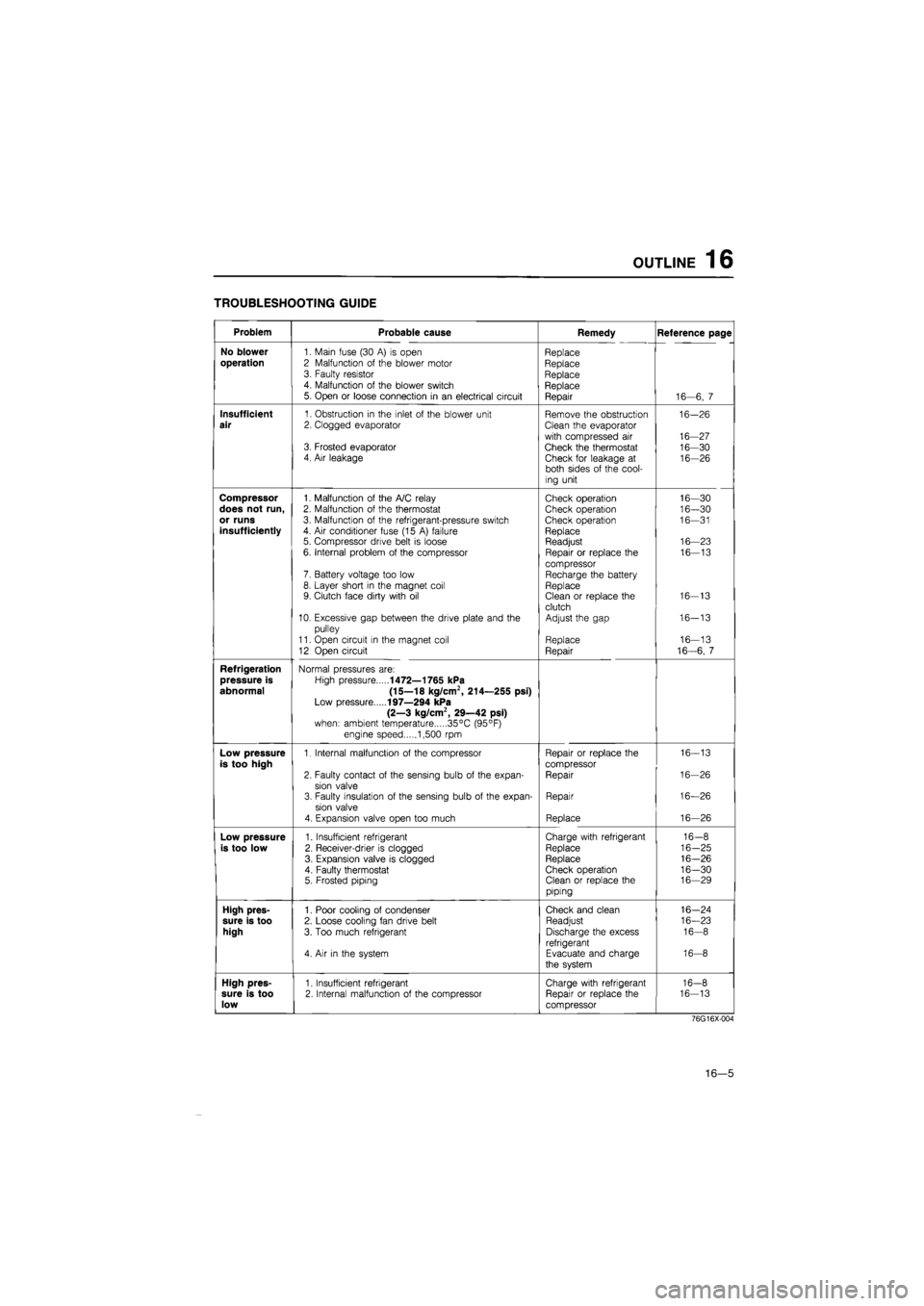
TROUBLESHOOTING GUIDE
Problem Probable cause Remedy Reference page
No blower
1. Main fuse (30
A) is
open Replace
operation
2 Malfunction
of
the blower motor Replace 3. Faulty resistor Replace 4. Malfunction
of
the blower switch Replace 5. Open
or
loose connection
in an
electrical circuit Repair 16—6,
7
Insufficient
1. Obstruction
in
the inlet
of
the blower unit Remove the obstruction 16-26
air
2. Clogged evaporator Clean the evaporator
with compressed
air
16-27 3. Frosted evaporator Check the thermostat 16-30 4. Air leakage Check for leakage
at
16-26 both sides
of
the cool-
ing unit
Compressor
1. Malfunction
of
the A/C relay Check operation 16—30
does not run,
2. Malfunction
of
the thermostat Check operation 16—30
or runs
3. Malfunction
of
the refrigerant-pressure switch Check operation 16—31
insufficiently
4.
Air
conditioner fuse (15
A)
failure Replace 5. Compressor drive belt
is
loose Readjust 16—23
6. Internal problem
of
the compressor Repair
or
replace
the
16—13
compressor 7. Battery voltage too low Recharge the battery 8. Layer short
in
the magnet coil Replace 9. Clutch face dirty with
oil
Clean
or
replace the 16-13
clutch 10. Excessive gap between the drive plate and
the
Adjust the gap 16-13
pulley
11. Open circuit
in
the magnet coil Replace 16—13
12 Open circuit Repair 16-6,
7
Refrigeration
Normal pressures are:
pressure is
High pressure
1472—1765 kPa
abnormal (15—18 kg/cm2, 214—255 psi)
Low pressure
197—294 kPa
(2—3 kg/cm2, 29—42 psi)
when: ambient temperature 35°C (95°F)
engine speed 1,500
rpm
Low pressure
1. Internal malfunction
of
the compressor Repair
or
replace the 16-13
is too high
compressor
2. Faulty contact
of
the sensing bulb
of
the expan-Repair 16-26
sion valve 3. Faulty insulation
of
the sensing bulb
of
the expan-Repair 16—26
sion valve
4. Expansion valve open too much Replace 16—26
Low pressure
1. Insufficient refrigerant Charge with refrigerant 16-8
is too low
2. Receiver-drier
is
clogged Replace 16-25
3. Expansion valve
is
clogged Replace 16-26
4. Faulty thermostat Check operation 16-30 5. Frosted piping Clean
or
replace the 16—29
piping
High pres-
1. Poor cooling
of
condenser Check and clean 16-24
sure is too
2. Loose cooling fan drive belt Readjust 16—23
high
3. Too much refrigerant Discharge the excess 16-8
refrigerant 4.
Air in
the system Evacuate and charge 16-8
the system
High pres-
1. Insufficient refrigerant Charge with refrigerant 16-8
sure is too
2. Internal malfunction
of
the compressor Repair
or
replace the 16-13
low
compressor
76G16X-004
16—5
Page 1791 of 1865
16 OUTLINE
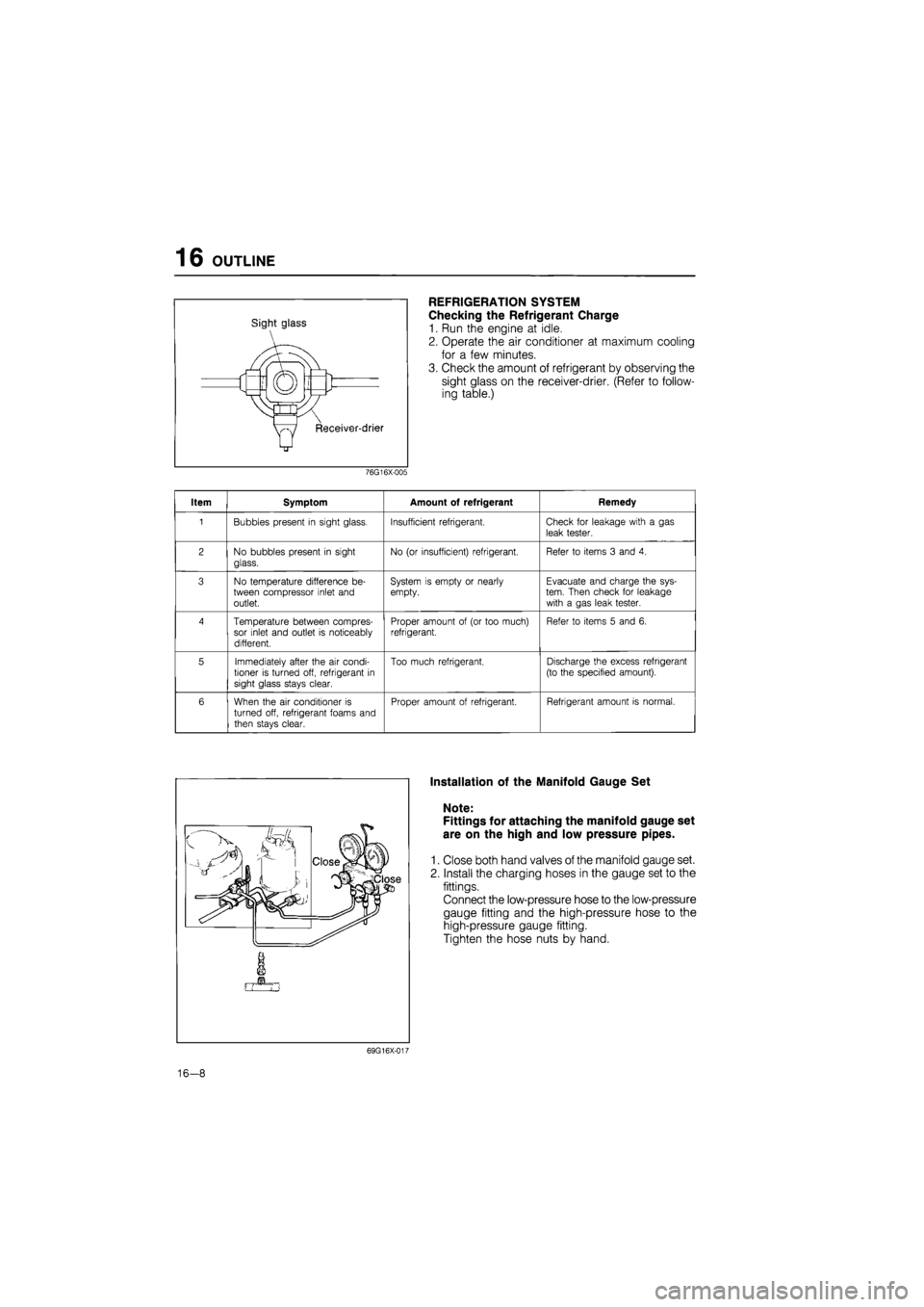
Sight glass
REFRIGERATION SYSTEM
Checking the Refrigerant Charge
1. Run the engine at idle.
2. Operate the air conditioner at maximum cooling
for a few minutes.
3. Check the amount of refrigerant by observing the
sight glass on the receiver-drier. (Refer to follow-
ing table.)
76G16X-005
Item Symptom Amount of refrigerant Remedy
1 Bubbles present
in
sight glass. Insufficient refrigerant. Check
for
leakage with
a gas
leak tester.
2 No bubbles present
in
sight
glass.
No
(or
insufficient) refrigerant. Refer
to
items
3
and
4.
3 No temperature difference
be-
tween compressor inlet and outlet.
System
is
empty
or
nearly empty. Evacuate and charge the sys-tem. Then check
for
leakage with
a
gas leak tester.
4 Temperature between compres-sor inlet and outlet
is
noticeably different.
Proper amount
of (or
too much) refrigerant. Refer
to
items
5
and
6.
5 Immediately after the
air
condi-tioner
is
turned off, refrigerant
in
sight glass stays clear.
Too much refrigerant. Discharge the excess refrigerant
(to the specified amount).
6 When the
air
conditioner
is
turned off, refrigerant foams and
then stays clear.
Proper amount
of
refrigerant. Refrigerant amount
is
normal.
Installation of the Manifold Gauge Set
Note:
Fittings for attaching the manifold gauge set
are on the high and low pressure pipes.
1. Close both hand valves of the manifold gauge set.
2. Install the charging hoses in the gauge set to the
fittings.
Connect the low-pressure hose to the low-pressure
gauge fitting and the high-pressure hose to the
high-pressure gauge fitting.
Tighten the hose nuts by hand.
69G16X-017
16-8
Page 1794 of 1865
OUTLINE 16
Leak-Testing the System
After finishing the evacuation of the system, check
it for leaks.
1. Install the refrigerant container valve.
2. Open the high-pressure manual valve to charge
the system with refrigerant gas.
3. When the low-pressure gauge reads 98.1 kPa (1
kg/cm2, 14.2 psi), close the high-pressure man-
ual valve.
4. Using a halide gas leak detector, propane torch,
or electric leak detector, check the system for leaks.
If a leak is found, repair the faulty component or
connection, then evacuate the system.
76G16X-632
Charging the System
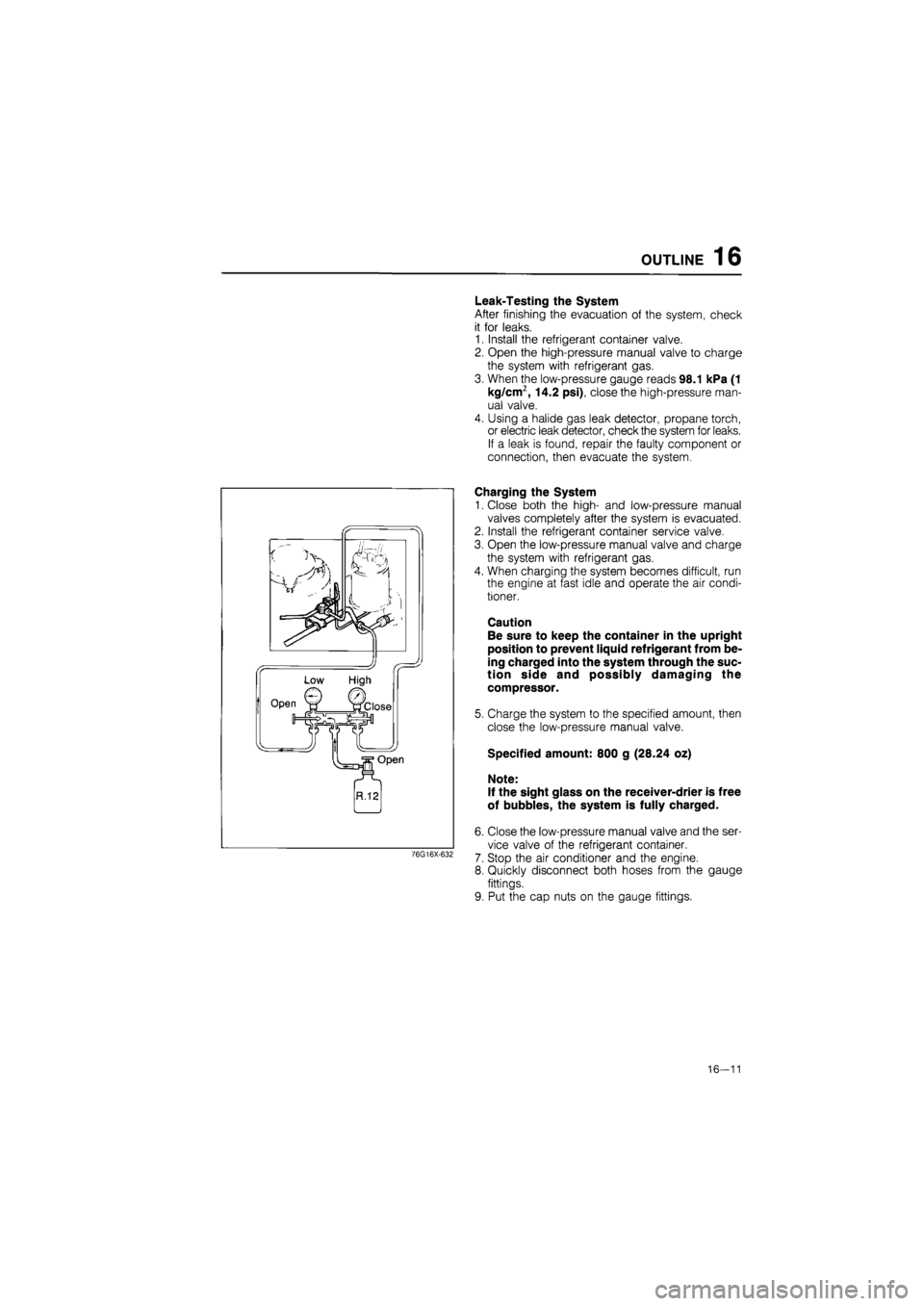
1. Close both the high- and low-pressure manual
valves completely after the system is evacuated.
2. Install the refrigerant container service valve.
3. Open the low-pressure manual valve and charge
the system with refrigerant gas.
4. When charging the system becomes difficult, run
the engine at fast idle and operate the air condi-
tioner.
Caution
Be sure to keep the container in the upright
position to prevent liquid refrigerant from be-
ing charged into the system through the suc-
tion side and possibly damaging the
compressor.
5. Charge the system to the specified amount, then
close the low-pressure manual valve.
Specified amount: 800 g (28.24 oz)
Note:
If the sight glass on the receiver-drier is free
of bubbles, the system is fully charged.
6. Close the low-pressure manual valve and the ser-
vice valve of the refrigerant container.
7. Stop the air conditioner and the engine.
8. Quickly disconnect both hoses from the gauge
fittings.
9. Put the cap nuts on the gauge fittings.
16—11