ECU MAZDA 626 1987 Repair Manual
[x] Cancel search | Manufacturer: MAZDA, Model Year: 1987, Model line: 626, Model: MAZDA 626 1987Pages: 1865, PDF Size: 94.35 MB
Page 1361 of 1865

ENGINE SPEED SENSING POWER STEERING 1 0
3. Tap in a new roll pin.
86U10X-175
i V
vlM^lPl'' \f ) j//
/f
Boot
1. Apply grease to the inner surface of the small end
of the boot.
2. Install the boot. Wrap a new wire around the large
end of the boot two times and then twist it 4 to 4.5
times. Bend the twisted part toward the mounting
bracket.
Note
Be careful not to break the boot wire.
3. Install the spring clip on the small end of the boot.
86U10X-176
Tie-rod end
Align with the mark made before disassembly, and
then tighten the nut.
86U10X-177
Oil pipe
Secure the mounting bracket in a vise so that the oil
pipe connections face upward.
86U10X-178
10-73
Page 1364 of 1865

1 0 ELECTRONICALLY-CONTROLLED POWER STEERING
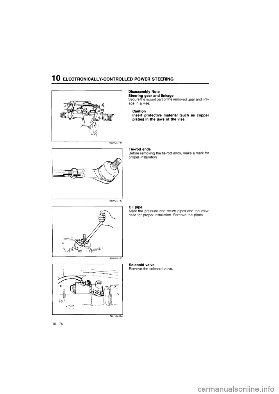
Disassembly Note
Steering gear and linkage
Secure the mount part of the removed gear and link-
age in a vise.
Caution
Insert protective material (such as copper
plates) in the jaws of the vise.
86U10X-181
Tie-rod ends
Before removing the tie-rod ends, make a mark for
proper installation.
86U10X-182
Oil pipe
Mark the pressure and return pipes and the valve
case for proper installation. Remove the pipes.
86U10X-183
Solenoid valve
Remove the solenoid valve.
86U10X-184
10—76
Page 1376 of 1865

1 0 ELECTRICAL COMPONENTS OF ELECTRONICALLY-CONTROLLED POWER STEERING (ECPS)
76G10X-020
76G10X-021
Checking Condition
Condition A
1. Turn the ignition switch OFF.
2. Start the engine and let it idle.
3. Turn the steering wheel to the straight-ahead po-
sition, and check the output pattern.
Refer to page 10—89 for other patterns and indi-
cated failure points.
Condition B
1. Turn the ignition switch OFF.
2. Start the engine and let it idle.
3. Turn the steering wheel 45° left and right from the
center, and check the output pattern.
Refer to page 10—89 for other patterns and indi-
cated failure points.
Condition C
1. Turn the ignition switch OFF.
2. Place the vehicle on a chassis roller tester. Block
the rear wheels, and secure it with chains.
3. Start the engine. Put the transmission in gear and
operate the vehicle at more than 10 km/h (6.2
mph).
4.Check the output pattern.
76G10X-022
Normal pattern
4 4V
Normal pattern Normal pattern
uV
Refer to page 10—90 for other patterns and indi-
cated failure points.
Note
For vehicles equipped with ABS, the ABS
warning light may come on. This is not a fail-
ure. The light will go off when turning the ig-
nition switch OFF and back ON.
86U10X-213
10—88
Page 1384 of 1865

1 0 ELECTRICAL COMPONENTS OF 4-WHEEL STEERING
Condition B
1. Place the vehicle on a chassis roller tester. Block
the rear wheels, and secure it with chains.
2. Turn the ignition switch OFF.
3. Start the engine after the ignition switch has been
OFF for at least 10 seconds. Put the transmission
in gear and operate the vehicle at more than 40
km/h (25 mph).
4. Check if the 4WS warning light flashes or il-
luminates within 60 seconds.
5.
If
flashing or illumination occurs, inspect the circuit
by referring to the table below.
76G10X045
Diagnosis Output Pattern
Warning light output pattern
0.5 sec —i 2.5 sec
Malfunction
Normal operation, control unit or wir-ing harness
Speed sensors or
wiring harness
Flow chart
No.
4WS—0
4WS—1
Rear steering gear
assembly
Solenoid valve or wiring harness
Stepper motor or wiring harness
Rear-to-front steer-ing ratio sensor or wiring harness
4WS—2
4WS—3
4WS—4
4WS—5
86U10X-225
10-96
Page 1423 of 1865

POWER BRAKE UNIT 1 1
76G11X-071
Disassembly Note
Front and rear shells
1. Secure the front shell studs in a vise after attach-
ing suitable nuts to them to prevent damage to the
studs.
2. Before separating the front and rear shell assem-
blies, make matching marks to be used in reas-
sembly.
3. Fit a wrench onto the rear shell studs; then fasten
two of them with suitable nuts.
4. Rotate the rear shell counterclockwise to unlock.
Caution
The rear shell is spring loaded; loosen it
carefully.
Retainer key
Depress the plunger rod fully; then remove the re-
tainer key.
86U11X-049
86U11X-050
Assembly Note
Application of Grease
Before assembly, coat the parts shown in the figure
with silicon grease.
(1) Entire surface of reaction disc
(2) Dust seal lip
(3) Push rod
(4) Diaphragm-to-shell contacting surfaces
(5) Power piston
(6) Valve plunger oil seal
Retainer key
1. Push down the plunger rod.
2. Align the groove of the valve plunger with the slot
of the power piston.
3. Insert the retainer key.
86U11X-051
11—31
Page 1443 of 1865

REAR DISC BRAKE 1 1
86U11X-093
86U11X-094
86U11X-095
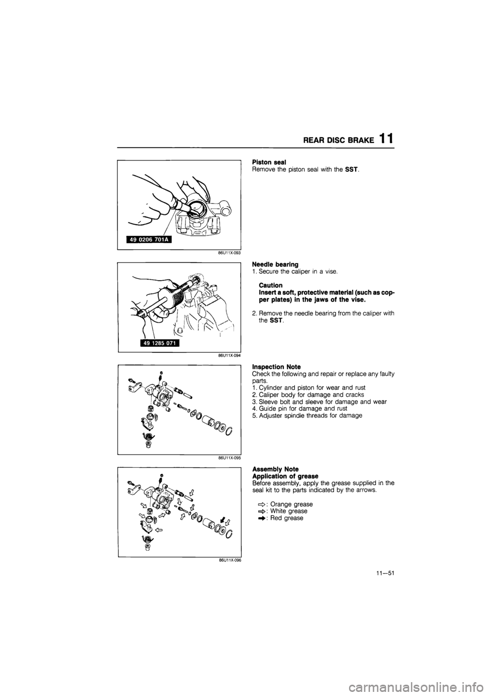
Piston seal
Remove the piston seal with the SST.
Needle bearing
1. Secure the caliper in a vise.
Caution
Insert a soft, protective material (such as cop-
per plates) in the jaws of the vise.
2. Remove the needle bearing from the caliper with
the SST.
Inspection Note
Check the following and repair or replace any faulty
parts.
1. Cylinder and piston for wear and rust
2. Caliper body for damage and cracks
3. Sleeve bolt and sleeve for damage and wear
4. Guide pin for damage and rust
5. Adjuster spindle threads for damage
Assembly Note
Application of grease
Before assembly, apply the grease supplied in the
seal kit to the parts indicated by the arrows.
Orange grease
White grease
Red grease
86U11X096
11-51
Page 1456 of 1865

1 1 REAR DRUM BRAKE
Brake drum
1. Move the quadrant against the backing plate with
a screwdriver and increase the shoe clearance.
2. Install the brake drum.
Note
The shoe clearance will be automatically ad-
justed by applying the parking brakes.
76G11X089
Locknut
Tighten the new locknut to the specified torque and
securely stake it to the spindle groove.
Tightening torque:
98—177
N
m (10—18 m-kg, 72—130 ft-lb)
Caution
Do not use a pointed tool for staking.
86U11X-129
11-64
Page 1480 of 1865

1 1 ANTI-LOCK BRAKE SYSTEM (ABS)
86U11X-170
86U11X-171
Removal of Front Wheel Speed Sensor
1. Remove the wheel and tire.
2. Remove the parts shown in the figure, and remove
the sensor from the knuckle.
Installation of Front Wheel Speed Sensor
1. Install the sensor to the knuckle.
Tightening torque:
16—23 N m (1.6—2.3 m-kg, 12—17 ft-lb)
Caution
The left and right sensors are not interchange-
able. L or R is indicated on the bracket.
2. Install the sensor harness bracket onto the knuckle.
Tightening torque:
16—23 Nm (1.6—2.3 m-kg, 12—17 ft-lb)
3. Push the sensor harness through the splash shield
and secure it with the clip.
4. Install the sensor harness bracket to the body.
Tightening torque:
16—23 Nm (1.6—2.3 m-kg, 12—17 ft-lb)
Caution
Verify that the harness is not twisted and does
not contact the shock absorber or body when
the steering wheel is turned.
5. Connect the sensor connector.
6. Install the wheel and tire.
86U11X-172
11-88
Page 1485 of 1865

ANTI-LOCK BRAKE SYSTEM (ABS) 1 1
Installation of Rear Sensor Rotor
Install in the reverse order of removal, referring to installation note for the specially marked parts.
Torque specifications
86U11X-184
Installation
Sensor rotor
Press the sensor rotor onto the hub with the SST.
86U11X-185
Locknut
1. Install and tighten the locknut.
2. Stake a new locknut securely in the driveshaft
groove.
Caution
Do not use a pointed tool for staking.
3. Check that the hub rotates freely by hand.
86U11X-186
11—93
Page 1513 of 1865
![MAZDA 626 1987 Repair Manual
1 3 FRONT SHOCK ABSORBER AND SPRING
76G13X-015
I N
49 G034 102 1
| 49 G034 103 | iBHssfllil 49 G034 101 |
mmy
LojaiiaiciS]
86U13X-018
76G13X-016
Disassembly Note
1. Loosen the piston rod up MAZDA 626 1987 Repair Manual
1 3 FRONT SHOCK ABSORBER AND SPRING
76G13X-015
I N
49 G034 102 1
| 49 G034 103 | iBHssfllil 49 G034 101 |
mmy
LojaiiaiciS]
86U13X-018
76G13X-016
Disassembly Note
1. Loosen the piston rod up](/img/28/57059/w960_57059-1512.png)
1 3 FRONT SHOCK ABSORBER AND SPRING
76G13X-015
I N
49 G034 102 1
| 49 G034 103 | iBHssfllil 49 G034 101 |
mmy
LojaiiaiciS]
86U13X-018
76G13X-016
Disassembly Note
1. Loosen the piston rod upper nut several turns, bu
do not remove.
Caution
a) Do not remove the nut.
b) Use copper or aluminum plates in the jawj
of a vice.
2. Set the SST in a vise.
3. Secure the shock absorber in the SST.
4. Compress the coil spring with the SST, then re
move the upper nut.
5. Remove the coil spring.
Inspection Note
Check the following and repair or replace any fault}
parts.
1. Oil leakage or abnormal noise from shock ab
sorbers
2. Deterioration or damage of mounting block anc
bearing
3. Wear or damage of bound stopper
4. Smooth rotation of control rod (AAS)
86U13X-020
13—16