differential MAZDA 626 1987 Workshop Manual
[x] Cancel search | Manufacturer: MAZDA, Model Year: 1987, Model line: 626, Model: MAZDA 626 1987Pages: 1865, PDF Size: 94.35 MB
Page 315 of 1865

2 A TROUBLESHOOTING GUIDE
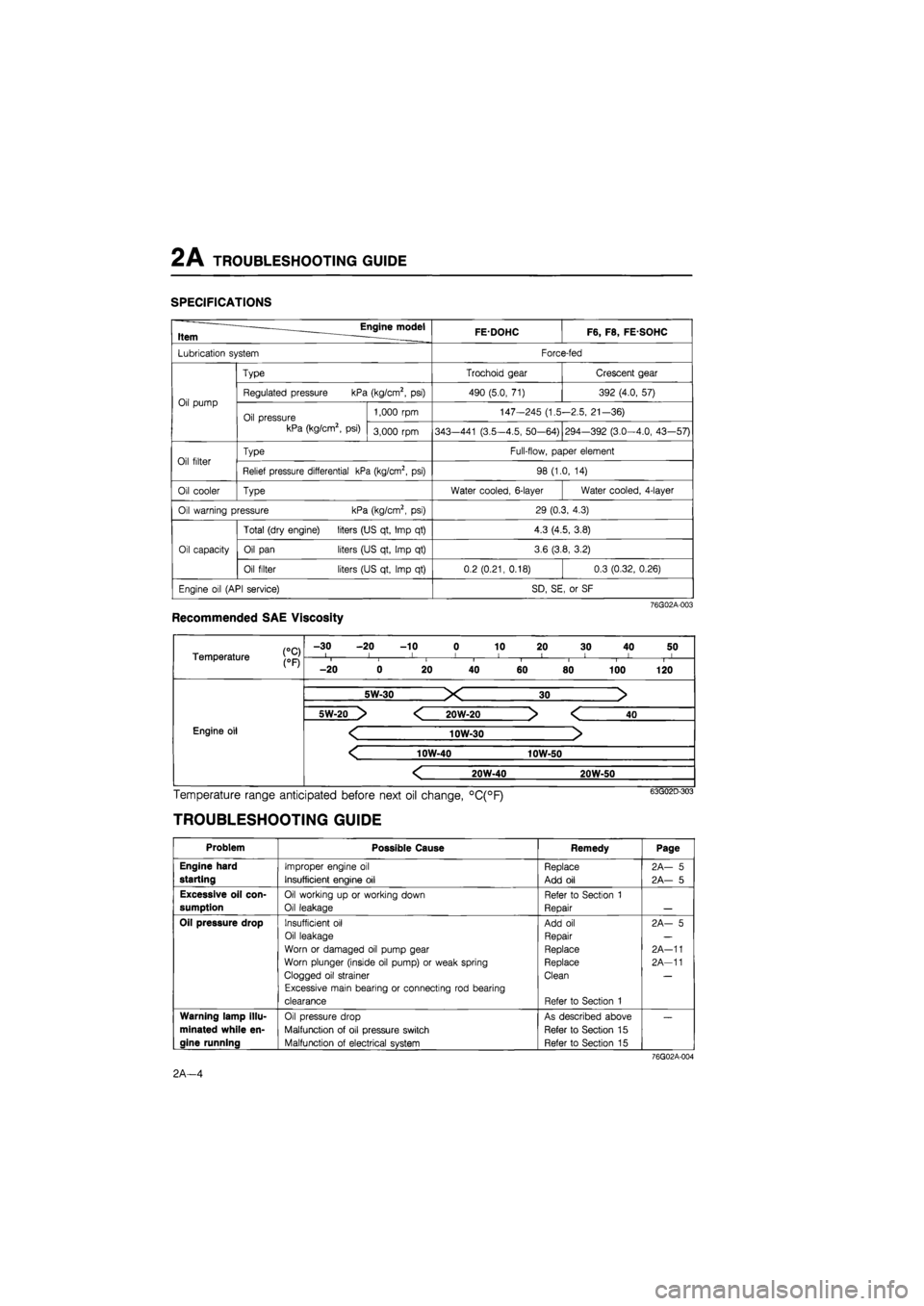
SPECIFICATIONS
Engine model Item . FEDOHC F6, F8, FE SOHC
Lubrication system Force-fed
Oil pump
Type Trochoid gear Crescent gear
Oil pump Regulated pressure kPa (kg/cm2, psi) 490 (5.0, 71) 392 (4.0, 57) Oil pump
Oil pressure kPa (kg/cm2, psi)
1,000 rpm 147-245 (1.5-2.5, 21-36) Oil pump
Oil pressure kPa (kg/cm2, psi) 3,000 rpm 343—441 (3.5-4.5, 50-64) 294-392 (3.0-4.0, 43—57)
Oil filter Type Full-flow, paper element Oil filter Relief pressure differential kPa (kg/cm2, psi) 98 (1.0, 14)
Oil cooler Type Water cooled, 6-layer Water cooled, 4-layer
Oil warning pressure kPa (kg/cm2, psi) 29 (0.3, 4.3)
Oil capacity
Total (dry engine) liters (US qt, Imp qt) 4.3 (4.5, 3.8)
Oil capacity Oil pan liters (US qt, Imp qt) 3.6 (3.8, 3.2) Oil capacity
Oil filter liters (US qt, Imp qt) 0.2 (0.21, 0.18) 0.3 (0.32, 0.26)
Engine oil (API service) SD, SE, or SF
76G02A-003
Recommended SAE Viscosity
Temperature j0pj
-30 -20 -10 0 10 20 30 40 50 I l I I 1 < ! I I Temperature j0pj i i i i I i 1 1
-20 0 20 40 60 80 100 120
Engine oil Engine oil
5W-30 X 30 >
Engine oil Engine oil
5W-20 > < 20W-20 > < 40
Engine oil < 10W-30 > Engine oil
< 10W-40 10W-50
Engine oil Engine oil
< 20W-40 20W-50
Engine oil
Temperature range anticipated before next oil change, °C(°F)
TROUBLESHOOTING GUIDE
Problem Possible Cause Remedy Page
Engine hard
starting
Improper engine oil
Insufficient engine oil
Replace
Add oil
2A— 5
2A— 5
Excessive oil con-
sumption
Oil working up or working down
Oil leakage
Refer to Section 1
Repair
Oil pressure drop Insufficient oil
Oil leakage
Worn or damaged oil pump gear
Worn plunger (inside oil pump) or weak spring
Clogged oil strainer
Excessive main bearing or connecting rod bearing
clearance
Add oil
Repair
Replace
Replace
Clean
Refer to Section 1
2A- 5
2A-11
2A-11
Warning lamp illu-
minated while en-
gine running
Oil pressure drop
Malfunction of oil pressure switch
Malfunction of electrical system
As described above
Refer to Section 15
Refer to Section 15
76G02A-004
2A—4
Page 327 of 1865

OUTLINE 2B
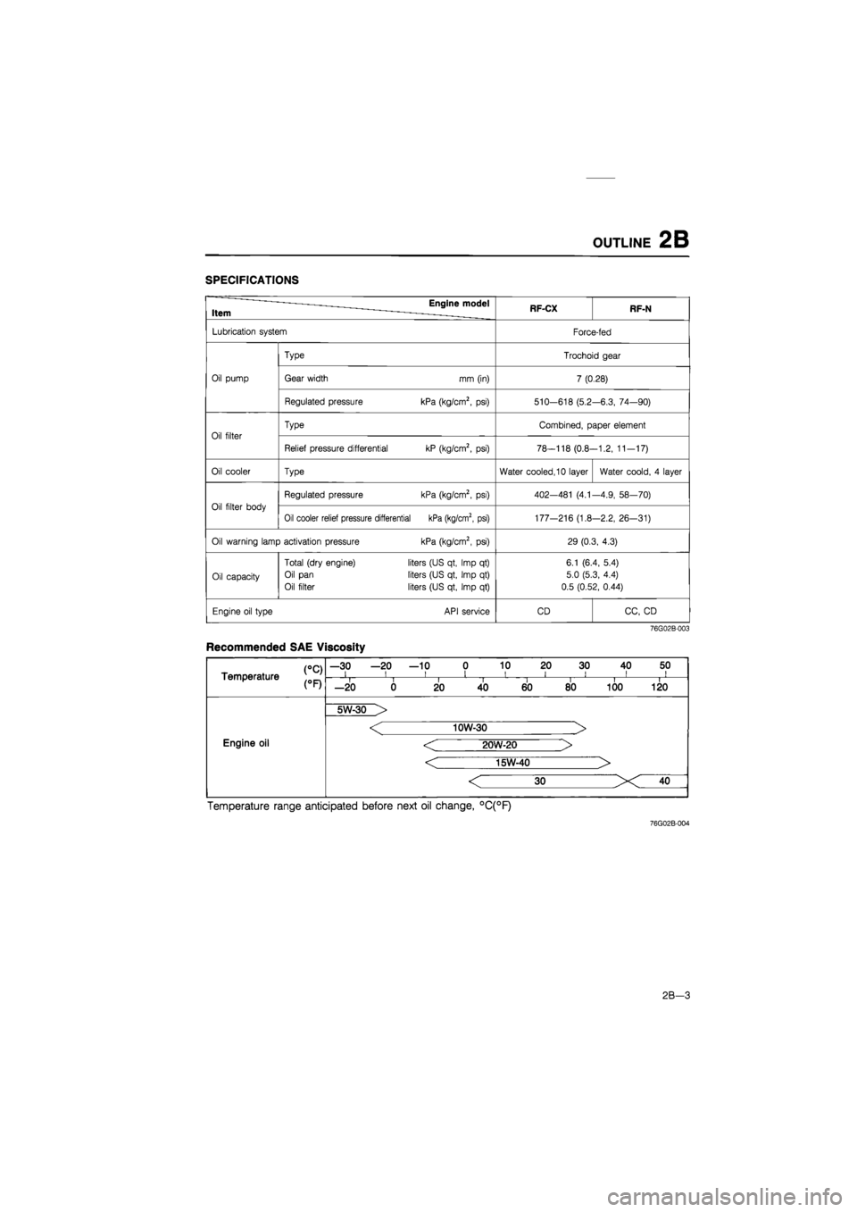
SPECIFICATIONS
Item Engine model RF-CX RF-N
Lubrication system Force-fed
Type Trochoid gear
Oil pump Gear width mm (in) 7 (0.28)
Regulated pressure kPa (kg/cm2,
psi)
510-618 (5.2 -6.3, 74—90)
Oil filter
Type Combined, paper element
Oil filter
Relief pressure differential kP (kg/cm2,
psi)
78-118 (0.8--1.2, 11-17)
Oil cooler Type Water cooled, 10 layer Water coold,
4
layer
Oil filter body
Regulated pressure kPa (kg/cm2,
psi)
402—481
(4.1
-4.9, 58—70)
Oil filter body
Oil cooler relief pressure differential kPa (kg/cm2, psi) 177-216 (1.8 -2.2, 26-31)
Oil warning lamp activation pressure kPa (kg/cm2,
psi)
29 (0.3, 4.3)
Oil capacity
Total (dry engine)
Oil pan
Oil filter
liters (US qt, Imp
qt)
liters (US qt, Imp
qt)
liters (US qt, Imp
qt)
6.1 (6.4, 5.4)
5.0 (5.3, 4.4)
0.5 (0.52, 0.44)
Engine oil type API service CD CC,
CD
76G02B-003
Recommended SAE Viscosity
CC) Temperature
—30 —20 —10 0 10 20 30 40 50 i i i i i i i ii CC) Temperature i i II i i i i —20 0 20 40 60 80 100 120
Engine oil
5W-30 >
Engine oil
< 10W-30 >
< 20W-20 >
< 15W-40 >
Engine oil
Temperature range anticipated before next oil change, °C(°F)
76G02B-004
2B-3
Page 808 of 1865

7A OUTLINE
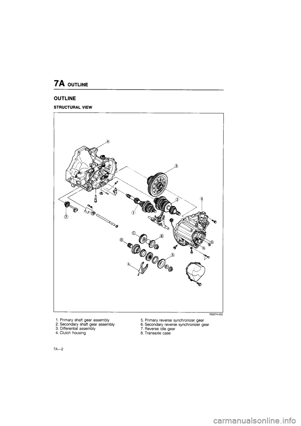
OUTLINE
STRUCTURAL VIEW
76G07A-002
1. Primary shaft gear assembly
2. Secondary shaft gear assembly
3. Differential assembly
4. Clutch housing
5. Primary reverse synchronizer gear
6. Secondary reverse synchronizer gear
7. Reverse idle gear
8. Transaxle case
7A—2
Page 811 of 1865

TROUBLESHOOTING GUIDE 7A
TROUBLESHOOTING GUIDE
Problem Possible cause Remedy Page
Change lever won't Seized change lever ball Replace 7A-58 shift smoothly, or is Seized change control rod joint Replace 7A-58
hard to shift Bent change control rod Replace 7A-58
Too much play in Worn change control rod bushing Replace 7A-58 change lever Weak spring of ball or change lever Replace 7A-58 Worn bushing of ball or change lever Replace 7A—58
Difficult to shift Bent change rod Replace 7A—58
No grease in transmission control Lubricate with grease 7A-58
Insufficient oil Add oil 7A-6
Deterioration of oil quality Replace with oil of 7A-6 specified quality
Wear or play of shift fork or shift rod Replace 7 A—18
Wear of synchronizer ring Replace 7A-27
Wear of synchronizer cone of gear Replace 7A-27
Bed contact of synchronizer ring and cone of Replace 7A-27 gear
Excessive longitudinal play of gears Replace 7A-22
Wear of bearing Adjust or replace 7A—22
Wear of synchronizer key spring Replace 7A-27
Excessive shaft gear bearing preload Adjust 7A-37
Improperly adjusted change guide plate Adjust 7A-20
Won't stay in gear Bent change control rod Replace 7A-58
Worn change control rod bushing Replace 7A-58
Weak change lever ball spring Replace 7A-58
Improperly installed extension bar Tighten 7A-58
Wear of shift fork Replace 7A—22
Wear of clutch hub Replace 7A-27
Worn clutch hub sleeve Replace 7A-27
Worn gear sliding part of both shaft gears Replace 7A-26
Worn gear sliding part of each gear Replace 7A-26
Worn steel sliding groove of control end Replace 7 A—18
Weak spring pressing against steel ball Replace 7A-18
Excessive thrust clearance Replace 7A—33,35
Worn bearing Replace 7A—22
Improperly installed engine mount Tighten 7A—49
Abnormal noise Insufficient oil Add oil 7A-6
Deterioration of oil quality Replace 7A-6
Worn bearing Adjust or replace 7A-22
Worn gear sliding surface of both shaft gears Replace 7A—26
Wear of sliding surfaces of gears Replace 7A-26
Excessive thrust clearance Replace 7A—33,35
Damaged gear teeth Replace with oil of 7A-26
specified quality Foreign material in gears Replace 7A-22
Damaged differential gear, or excessive backlash Adjust or replace 7A—30
76G07A-005
7A-5
Page 822 of 1865

7A REMOVAL
19. Install the SST to the differential side gear.
Note
Failure to install the SST may cause the
differential side gears to become misposi-
tioned.
86U07A-027
20. Remove the gusset plates, (except DOHC)
21. Remove the under cover, (except DOHC)
22. Remove the extension bar and the control rod.
76G07A-014
23. Remove the surge tank bracket. (Fl)
24. Remove the starter.
76G07A-015
25. Suspend the engine with the SST.
86U07A-030
7 A-16
Page 824 of 1865

7A DISASSEMBLY
DISASSEMBLY
STEP 1
Disassemble in the sequence shown in the figure referring to disassembly note for the specially marked
parts.
76G07A-016
76G07A-017
24. Crank lever shaft
25. O-ring
26. Crank lever assembly
27. Shift fork and shift rod as-
sembly
28. Steel ball
29. Spring
30. Primary shaft gear as-
sembly
31. Secondary shaft gear as-
sembly
32. Differential assembly
33. Clutch housing
1. Rear cover
2. Lock nut
3. Lock nut
4. Primary reverse synchroniz-
er gear
5. Secondary reverse syn-
chronizer gear
6. Roll pin
7. Shift fork
8. Clutch hub assembly
9. Synchronizer ring
10. 5th gear
11. Gear sleeve
12. Secondary 5th gear
13. Lock bolt
14. Guide bolt
15. Lock bolt, ball and spring
16. Transaxle case
17. Magnet
18. Reverse idle shaft
19. Reverse idle gear
20. Lock bolt
21. Shift rod (5th and reverse)
and clip
22. Gate
23. Pin
7 A—18
Page 827 of 1865

DISASSEMBLY 7 A
Disassembly Note
Bearing outer race (primary shaft)
Remove the bearing outer race with the SST.
86U07A-041
Bearing outer race (secondary shaft)
Remove the bearing outer race by lifting out the fun-
nel and race together.
86U07A-042
Roll pin
Align the groove for removal of the clutch housing
pin with the position of the roll pin, then tap the pin
out using a pin punch.
76G07A-020
Bearing outer race (differential)
Remove the bearing outer race with the SST.
86U07A-044
7A-21
Page 831 of 1865

DISASSEMBLY 7A
STEP 4 (DIFFERENTIAL)
Disassemble in the sequence shown in the figure referring to disassembly note for the specially marked
parts.
Note
a) If the bearing inner races are removed replace them with new ones.
b) Before disassembly, check the backlash of the side gears and pinion gears.
(Refer to page 7A—30)
1. Knock pin
2. Pinion shaft
3. Pinion gear
4. Thrust washer
5. Side gear
6. Thrust washer
7. Side bearing in-
ner race
8. Speedometer
drive gear
9. Side bearing in-
ner race
10. Gear case
76G07A-026
Disassemble Note
Side bearing inner race (side opposite ring gear)
Remove the race from the gear case with the SST.
Caution
Hold the gear case with one hand so that it
does not fall.
76G07A-027
Side bearing inner race (ring gear side)
Remove the race with a combination of parts from
the SST.
86U07A-055
7A-25
Page 834 of 1865

7A INSPECTION
86U07A-058
63U07A-074
63U07A-075
Reverse Idle Gear
1. Worn or damaged bushing.
2. Worn or damaged teeth.
3. Worn or damaged release lever coupling groove.
4. Clearance between sleeve and reverse lever.
Standard: 0.095—0.318 mm (0.004—0.013 in)
Maximum: 0.5 mm (0.020 in)
Clutch Housing, Transaxle Case, Rear Cover,
and Differential Gear Case
Cracks or damage.
Caution
If the clutch housing, transaxle case, or
differential gear case is replaced, adjust the
bearing preload of the shaft gears and the
preload of the differential side bearings.
Bearing
1. Roughness or noise while turning
2. Worn or damaged outer race or rollers
Caution
a) Replace the bearing, the outer race, and the
inner race as a unit.
b)lf the bearing is replaced, adjust the
preload.
Speedometer Driven Gear Assembly
1. Worn or damaged teeth.
2. Worn or damaged O-ring.
Ring Gear Speedometer Drive Gear
Worn or damaged teeth.
Oil Seal
Damaged or worn lip.
63U07A-076
7A—28
Page 835 of 1865

ASSEMBLY 7 A
ASSEMBLY
Note
a) Wash all parts.
b) Apply oil to all friction surfaces.
c) Use new roll pins and retaining rings.
STEP 1 (DIFFERENTIAL)
86U07A-059
Assembly
1. Install the speedometer drive gear and the new
bearing inner race with the SST.
Note
Press to 19,620 N (2,000 kg, 4,400 lb).
2. Install the new bearing inner race with the SST.
Note
Press to 19,620 N (2,000 kg, 4,400 lb).
86U07A-061
7A-29