oil type MAZDA 626 1987 Workshop Manual
[x] Cancel search | Manufacturer: MAZDA, Model Year: 1987, Model line: 626, Model: MAZDA 626 1987Pages: 1865, PDF Size: 94.35 MB
Page 36 of 1865

1A TROUBLESHOOTING GUIDE
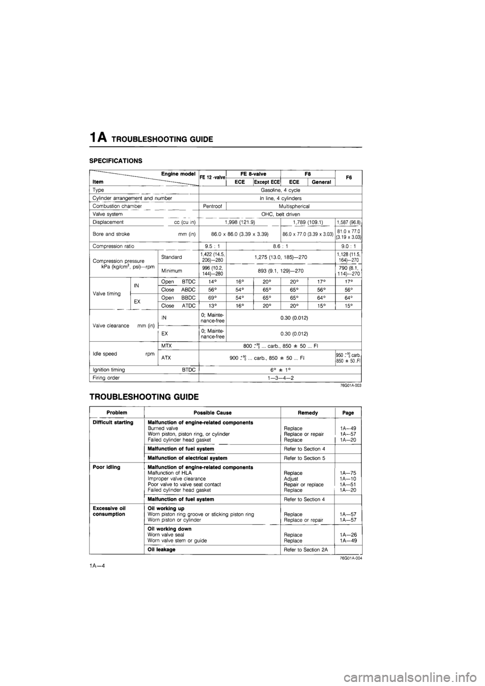
SPECIFICATIONS
——Engine model
Item ^ FE 12 -valve FE 8-valve F8 F6 ——Engine model
Item ^ FE 12 -valve ECE Except ECE ECE General F6
Type Gasoline, 4 cycle
Cylinder arrangement and number In line, 4 cylinders
Combustion chamber Pentroof Multispherical
Valve system OHC, belt driven
Displacement cc (cu in) 1,998 (121.9) 1,789 (109.1) 1,587 (96.8)
Bore and stroke mm (in) 86.0 x 86.0 (3.39 x 3.39) 86.0 x 77.0 (3.39 x 3.03) 81.0 x 77.0 (3.19 x 3.03)
Compression ratio 9.5 : 1 8.6 : 1 9.0 : 1
Compression pressure kPa (kg/cm2, psi)—rpm
Standard 1,422 (14.5,
206)—280 1,275 (13.0, 185)—270 1,128 (11.5, 164)—270 Compression pressure kPa (kg/cm2, psi)—rpm Minimum 996 (10.2,
144)—280 893 (9.1, 129)—270 790 (8.1, 114)—270
Valve timing
IN Open BTDC 14° 16° 20° 20° 17° 17°
Valve timing
IN Close ABDC 56° 54° 65° 65° 56° 56° Valve timing
EX Open BBDC 69° 54° 65° 65° 64° 64° Valve timing
EX Close ATDC 13° 16° 20° 20° 15° 15°
Valve clearance mm (in)
IN 0; Mainte-nance-free 0.30 (0.012)
Valve clearance mm (in)
EX 0; Mainte-nance-free 0.30 (0.012)
Idle speed rpm
MTX 800 _+5S ... carb., 850 ± 50 ... Fl
Idle speed rpm ATX 900 _+5g ... carb., 850 ± 50 ... Fl 950 _+5§ carb. 850 ±
50
.Fl
Ignition timing BTDC 6° ± 1°
Firing order
1
-3-4-2
76G01A-003
TROUBLESHOOTING GUIDE
Problem Possible Cause Remedy Page
Difficult starting Malfunction of engine-related components
Burned valve Worn piston, piston ring, or cylinder Failed cylinder head gasket
Replace Replace or repair Replace
1A-49
1A-57
1
A—20
Malfunction of fuel system Refer to Section 4
Malfunction of electrical system Refer to Section 5
Poor idling Malfunction of engine-related components Malfunction of HLA Improper valve clearance Poor valve to valve seat contact Failed cylinder head gasket
Replace Adjust Repair or replace Replace
1
A—75 1A-10 1 A—51
1
A—20
Malfunction of fuel system Refer to Section 4
Excessive oil
consumption
Oil working up Worn piston ring groove or sticking piston ring Worn piston or cylinder Replace Replace or repair
1
A—57 1A—57
Oil working down
Worn valve seal
Worn valve stem or guide Replace
Replace
1A—26
1A—49
Oil leakage Refer to Section 2A
76G01A-004
1A—4
Page 57 of 1865

ON-VEHICLE MAINTENANCE (CYLINDER HEAD) 1 A
76G01A-035
Engine harness connector
Install the engine harness connectors.
Distributor
1. Apply engine oil to the O-ring, and position it on
the distributor.
2. Apply engine oil to the blade or gear.
3. Align the mating marks as shown in the figure
...8-valve.
4. Install the distributor with the marks facing straight
up.
5. Loosely tighten the distributor mounting bolt.
1. IG coil
2. Engine ground
3. Water tempera-
ture sensor
4. Water thermo
switch
5. Oxygen sensor
(Fl)
6. Injection harness
(Fl)
7. F/l solenoid
valve (Fl)
8. Throttle sensor
(Fl)
76G01A-113
Steps After Installation
1. Fill the radiator with the specified amount and type
of coolant.
2. Perform the necessary engine adjustments. (Re-
fer to TUNE-UP PROCEDURE.)
1
A—25
Page 65 of 1865

1 A ON-VEHICLE MAINTENANCE (VALVE SEAL)
Valve clearance (8-valve)
Adjust the valve clearance. (Refer to page
1
A—10.)
Cylinder head cover
1. Apply silicon sealant to the shaded areas shown
in the figure.
2. Install the cylinder head cover.
Tightening torque:
6—8 N-m (60—80 cm-kg, 52—69 in-lb)
76G01A-116
Distributor
1. Apply engine oil to the O-ring, and position it on
the distributor.
2. Apply engine oil to the blade or gear.
3. Align the mating marks as shown in the figure
...8-valve.
4. Install the distributor with the marks facing straight
up.
5. Loosely tighten the distributor mounting bolt.
76G01A-035
Steps After Installation
1. Fill the radiator with the specified amount and type
of coolant.
2. Perform the necessary engine adjustments. (Re-
fer to TUNE-UP PROCEDURE.)
86U01X-055
1A—33
Page 131 of 1865

INSTALLATION 1A
76G01A-099
76G01A-100
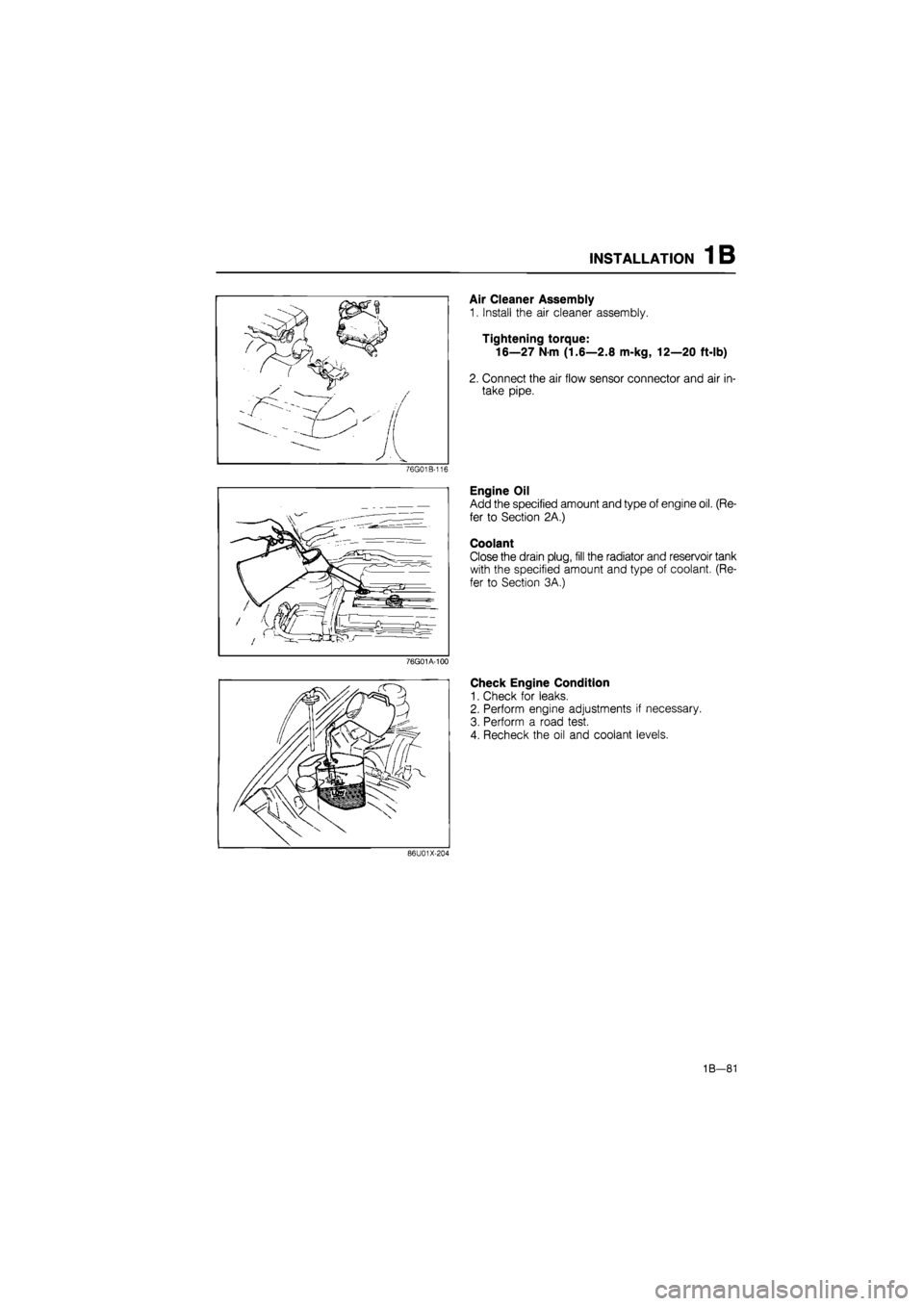
Air Cleaner Assembly
1. Install the air cleaner assembly.
Tightening torque:
16—27
N
m (1.6—2.8 m-kg, 12—20 ft-lb)
2. Connect the air flow sensor connector and air in-
take pipe (Fl).
Engine Oil
Add the specified amount and type of engine oil. (Re-
fer to Section 2A.)
Coolant
Close the drain plug, fill the radiator and reservoir tank
with the specified amount and type of coolant. (Re-
fer to Section 3A.)
Check Engine Condition
1. Check for leaks.
2. Perform engine adjustments if necessary.
3. Perform a road test.
4. Recheck the oil and coolant levels.
86U01X-204
1A—99
Page 134 of 1865

TROUBLESHOOTING GUIDE 1 B
SPECIFICATIONS
Engine model FE DOHC
Item Leaded fuel Unleaded fuel
Type Gasoline, 4 cycle
Cylinder arrangement and number In line, 4 cylinders
Combustion chamber Pentroof
Valve system OHC, belt driven
Displacement cc (cu in) 1,998 (121.9)
Bore and stroke mm (in) 86.0 x 86.0 (3.39 x 3.39)
Compression ratio 10.0 : 1 9.2 : 1
Compression pressure Standard 1,422 (14.5, 206)—290 1,373 (14.0, 199)—310
kPa (kg/cm2, psi)-rpm Minimum 996 (10.2, 144)—290 961 (9.8, 139)—310
IN Open BTDC 10° 10°
Valve timing
IN Close ABDC 60° 55° Valve timing
EX Open BBDC 60° 55° EX Close ATDC 10° 10°
Valve clearance mm (in) IN 0; Maintenance-free Valve clearance mm (in) EX 0; Maintenance-free
Idle speed rpm 750 ± 50
Ignition timing BTDC 12° ± 1°
Firing order 1—3--4-2
76G01B-002
TROUBLESHOOTING GUIDE
Problem Possible Cause Remedy Page
Difficult starting Malfunction of engine-related components
Burned valve
Worn piston, piston ring, or cylinder
Failed cylinder head gasket
Replace
Replace or repair Replace
1B—35 1B—43 1B—16
Malfunction of fuel system Refer to Section 4C
Malfunction of electrical system Refer to Section 5
Poor Idling Malfunction of engine-related components Malfunction of HLA
Poor valve to valve seat contact
Failed cylinder head gasket
Replace
Repair or replace
Replace
1B—60 1B—37 1B—16
Malfunction of fuel system Refer to Section 4C
Excessive oil
consumption Oil working up Worn piston ring groove or sticking piston ring Worn piston or cylinder
Replace
Replace or repair
1B-43 1B-43
Oil working down
Worn valve seal
Worn valve stem or guide
Replace
Replace 1B-35
Oil leakage Refer to Section 2A
76G01B-003
1B—3
Page 152 of 1865

ON-VEHICLE MAINTENANCE (CYLINDER HEAD) 1 B
Distributor
1. Apply engine oil to the O-ring, and position it on
the distributor.
2. Apply engine oil to the blade.
3. Install the distributor.
4. Loosely tighten the distributor mounting bolt.
76G01A-035
Engine harness connector
Install the engine harness connectors.
1. IG coil
2. Heat gauge unit
3. Speed sensor
4. P/S switch
5. Engine ground
6. Water tempera-
ture sensor
7. Water thermo
switch
8. Crank angle
sensor
9. Oxygen sensor
10. Linear solenoid
11. Solenoid valve
(idle speed
control)
12. Throttle position
sensor
13. Injection harness
76G01B-035
Steps After Installation
1. Fill the radiator with the specified amount and type
of coolant.
2. Perform the necessary engine adjustments. (Re-
fer to TUNE-UP PROCEDURE.)
86U01X-041
1B-21
Page 212 of 1865

INSTALLATION 1B
76G01A-100
Air Cleaner Assembly
1. Install the air cleaner assembly.
Tightening torque:
16—27
N
m (1.6—2.8 m-kg, 12—20 ft-lb)
2. Connect the air flow sensor connector and air in-
take pipe.
Engine Oil
Add the specified amount and type of engine oil. (Re-
fer to Section 2A.)
Coolant
Close the drain plug, fill the radiator and reservoir tank
with the specified amount and type of coolant. (Re-
fer to Section 3A.)
Check Engine Condition
1. Check for leaks.
2. Perform engine adjustments if necessary.
3. Perform a road test.
4. Recheck the oil and coolant levels.
86U01X-204
1B-81
Page 215 of 1865

TROUBLESHOOTING GUIDE 1 C
SPECIFICATIONS
———Engine model
Item ^—_______ RF-CX RF-N
Type Diesel, 4 cycle
Cylinder arrangement and number In line, 4 cylinders
Combustion chamber Swirl chamber
Valve system OHC, belt driven
Displacement cc (cu in) 1,998 (121.9)
Bore and stroke mm (in) 86.0 x 86.0 (3.39 x 3.39)
Compression ratio 21.1 : 1 22.7 : 1
Compression pressure
kPa (kg/cm2, psi)-rpm
Standard 2.943 (30, 427)-200 Compression pressure
kPa (kg/cm2, psi)-rpm Minimum 2.649 (27, 384)-200
Valve timing
IN Open BTDC 13° 13°
Valve timing
IN Close ABDC 15° 39° Valve timing
EX Open BBDC 60° 60° Valve timing
EX Close ATDC 8° 8°
Valve clearance mm (in)
Cold IN 0.25 (0.010)
Valve clearance mm (in)
Cold EX 0.35 (0.014) Valve clearance mm (in) Warm (for ref.)
IN 0.30 (0.012) Valve clearance mm (in) Warm (for ref.) EX 0.40 (0.016)
Idle speed (MTX in neutral) rpm 720
Injection timing ATDC 10 TDC 0°
Injection order 1_3_4_2
76G01C-002
TROUBLESHOOTING GUIDE
Problem Possible Cause Remedy Page
Difficult starting Malfunction of engine-related components
Burned valve Worn piston, piston ring, or cylinder Failed cylinder head gasket
Replace Replace or repair Replace
1C-48 1C—55,56 1C-16
Difficult starting
Malfunction of fuel system Refer to Section 4D
Difficult starting
Malfunction of Comprex supercharger Refer to Section 4D
Difficult starting
Malfunction of electrical system Refer to Section 5
Poor idling Malfunction of engine-related components Improper valve clearance Poor valve to valve seat contact Failed cylinder head gasket
Adjust Repair or replace Replace
1C-85 1C-50 1C—16
Poor idling
Malfunction of fuel system Refer to Section 4D
Poor idling
Malfunction of Comprex supercharger Refer to Section 4D
Excessive oil consumption
Oil working up Worn piston ring groove or sticking piston ring Worn piston or cylinder
Replace Replace or repair
1C-57 1C—55,56
Excessive oil consumption
Oil working down Worn valve seal Worn valve stem or guide
Replace Replace
1C-24 1C-48
Excessive oil consumption
Oil leakage Refer to Section 2B
76G01C-003
1C—3
Page 217 of 1865

TUNE-UP PROCEDURE 1C
4BG01 B-006
4BG01B-007
76G01C-237
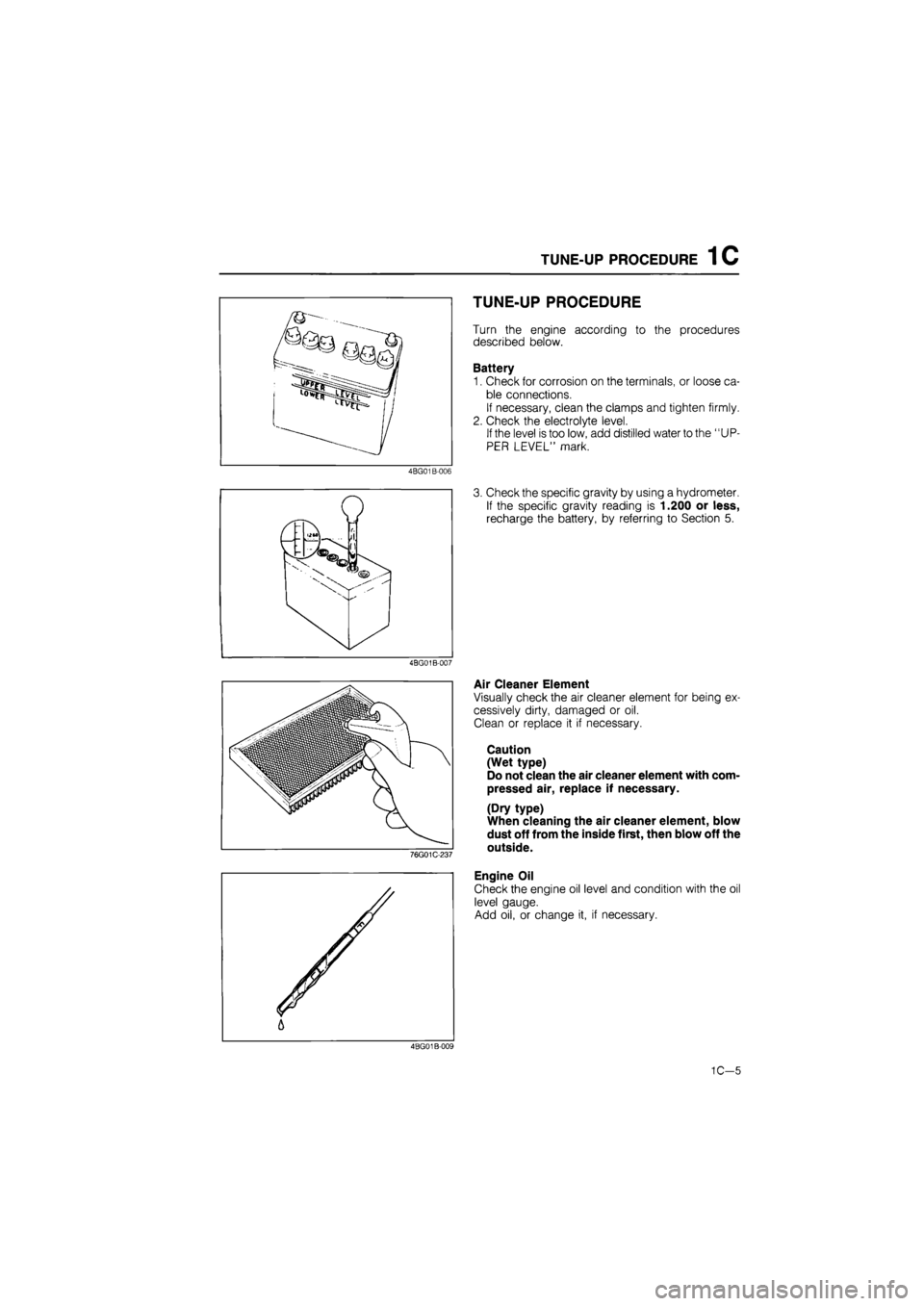
TUNE-UP PROCEDURE
Turn the engine according to the procedures
described below.
Battery
1. Check for corrosion on the terminals, or loose ca-
ble connections.
If necessary, clean the clamps and tighten firmly.
2. Check the electrolyte level.
If the level is too low, add distilled water to the "UP-
PER LEVEL" mark.
3. Check the specific gravity by using a hydrometer.
If the specific gravity reading is 1.200 or less,
recharge the battery, by referring to Section 5.
Air Cleaner Element
Visually check the air cleaner element for being ex-
cessively dirty, damaged or oil.
Clean or replace it if necessary.
Caution
(Wet type)
Do not clean the air cleaner element with com-
pressed air, replace if necessary.
(Dry type)
When cleaning the air cleaner element, blow
dust off from the inside first, then blow off the
outside.
Engine Oil
Check the engine oil level and condition with the oil
level gauge.
Add oil, or change it, if necessary.
4BG01B-009
1C—5
Page 300 of 1865

1 C ASSEMBLY (AUXILIARY PARTS)
76G01C-205
76G01C-206
76G01C-207
o e-
Oil Cooler Assembly
1. Clean the contact surfaces of the cylinder block
and oil filter assembly.
2. Install new O-rings, and apply a coat of engine oil.
3. Install the oil cooler assembly.
Tightening torque:
Bolt A: 8—11 N-m
(80—110 cm-kg, 69—95 in-lb)
Bolt B: 37—52 N-m
(3.8—5.3 m-kg, 27—38 ft-lb)
4. Connect the water hose.
Oil Filter
1. Install the oil filter cover.
Tightening torque:
8—11 N-m (80—110 cm-kg, 69—95 in-lb)
2. Apply a coat of engine oil to the filter rubber seal.
3. Install the oil filter until the rubber seal contacts the
oil cooler by hand. Then tighten it a 7/6 turn fur-
ther with a band type wrench.
Alternator
1. Install the alternator.
Tightening torque:
Bolt A: 19—26 N m
(1.9—2.6 m-kg, 14—19 ft-lb)
Bolt B: 37—52 N-m
(3.8—5.3 m-kg, 27—38 ft-lb)
2. Install the alternator drive belt, and adjust the belt
deflection. (Refer to page 1C—7)
76G01C-208
1C—88
expert22 ajia http://rutracker.org