fuel cap MAZDA 626 1987 Workshop Manual
[x] Cancel search | Manufacturer: MAZDA, Model Year: 1987, Model line: 626, Model: MAZDA 626 1987Pages: 1865, PDF Size: 94.35 MB
Page 14 of 1865

0 PRE-DELIVERY INSPECTION
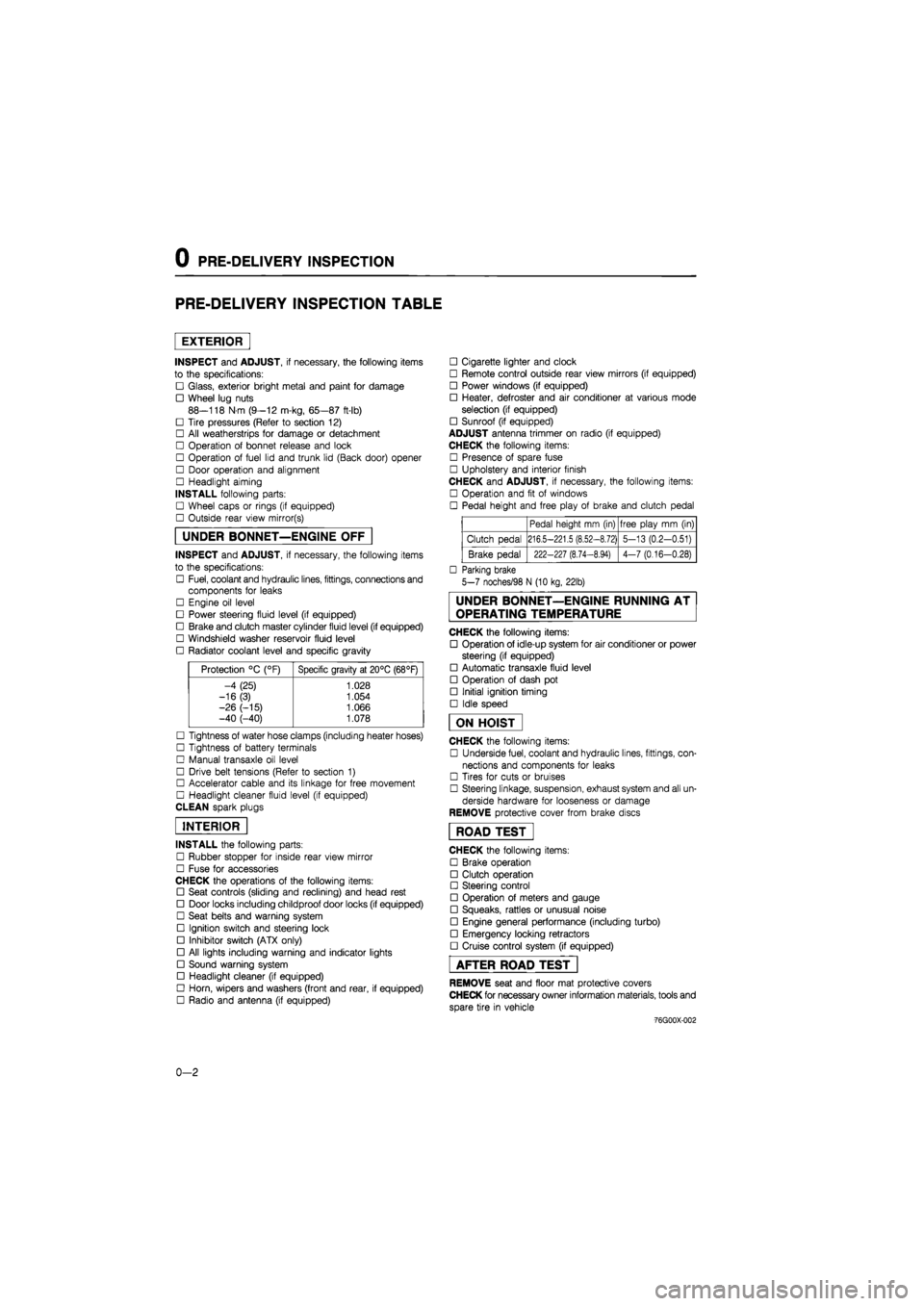
PRE-DELIVERY INSPECTION TABLE
EXTERIOR
INSPECT and ADJUST, if necessary, the following items
to the specifications:
• Glass, exterior bright metal and paint for damage
• Wheel lug nuts
88—118 N m (9—12 m-kg, 65—87 ft-lb)
• Tire pressures (Refer to section 12)
• All weatherstrips for damage or detachment
• Operation of bonnet release and lock
• Operation of fuel lid and trunk lid (Back door) opener
• Door operation and alignment
• Headlight aiming
INSTALL following parts:
• Wheel caps or rings (if equipped)
• Outside rear view mirror(s)
UNDER BONNET—ENGINE OFF
INSPECT and ADJUST, if necessary, the following items
to the specifications:
• Fuel, coolant and hydraulic lines, fittings, connections and
components for leaks
• Engine oil level
• Power steering fluid level (if equipped)
• Brake and clutch master cylinder fluid level (if equipped)
• Windshield washer reservoir fluid level
• Radiator coolant level and specific gravity
Protection °C (°F) Specific gravity at 20°C (68°F)
-4 (25) 1.028
-16(3) 1.054
-26 (-15) 1.066 -40 (-40) 1.078
• Tightness of water hose clamps (including heater hoses)
• Tightness of battery terminals
• Manual transaxle oil level
• Drive belt tensions (Refer to section 1)
• Accelerator cable and its linkage for free movement
• Headlight cleaner fluid level (if equipped)
CLEAN spark plugs
INTERIOR
INSTALL the following parts:
• Rubber stopper for inside rear view mirror
• Fuse for accessories
CHECK the operations of the following items:
• Seat controls (sliding and reclining) and head rest
• Door locks including childproof door locks (if equipped)
• Seat belts and warning system
• Ignition switch and steering lock
• Inhibitor switch (ATX only)
• All lights including warning and indicator lights
• Sound warning system
• Headlight cleaner (if equipped)
• Horn, wipers and washers (front and rear, if equipped)
• Radio and antenna (if equipped)
• Cigarette lighter and clock
• Remote control outside rear view mirrors (if equipped)
• Power windows (if equipped)
• Heater, defroster and air conditioner at various mode
selection (if equipped)
• Sunroof (if equipped)
ADJUST antenna trimmer on radio (if equipped)
CHECK the following items:
• Presence of spare fuse
• Upholstery and interior finish
CHECK and ADJUST, if necessary, the following items:
• Operation and fit of windows
• Pedal height and free play of brake and clutch pedal
Pedal height mm (in) free play mm (in)
Clutch pedal 216.5-221.5 (8.52-8.72) 5-13 (0.2-0.51)
Brake pedal 222-227 (8.74-8.94) 4-7 (0.16-0.28)
• Parking brake
5-7 noches/98 N (10 kg, 22lb)
UNDER BONNET—ENGINE RUNNING AT
OPERATING TEMPERATURE
CHECK the following items:
• Operation of idle-up system for air conditioner or power
steering (if equipped)
• Automatic transaxle fluid level
• Operation of dash pot
• Initial ignition timing
• Idle speed
ON HOIST
CHECK the following items:
• Underside fuel, coolant and hydraulic lines, fittings, con-
nections and components for leaks
• Tires for cuts or bruises
• Steering linkage, suspension, exhaust system and all un-
derside hardware for looseness or damage
REMOVE protective cover from brake discs
ROAD TEST"
CHECK the following items:
• Brake operation
• Clutch operation
• Steering control
• Operation of meters and gauge
• Squeaks, rattles or unusual noise
• Engine general performance (including turbo)
• Emergency locking retractors
• Cruise control system (if equipped)
AFTER ROAD TEST
REMOVE seat and floor mat protective covers
CHECK for necessary owner information materials, tools and
spare tire in vehicle
-76G00X-002
0-2
Page 17 of 1865

U1
Interval
Procedure & item
Number of Months or km, whichever corns first
©1 ©2 ©3 ©4 Service data and inspection point Page
Interval
Procedure & item
Months — 6 12 18 24 30 36 42 48 ©1 ©2 ©3 ©4 Service data and inspection point Page
Interval
Procedure & item
x 1000 Km
1 10 20 30 40 50 60 70 80 ©1 ©2 ©3 ©4 Service data and inspection point Page
Interval
Procedure & item
Miles x
1000 0.6 6 12 18 24 30 36 42 48
©1 ©2 ©3 ©4 Service data and inspection point Page
Battery electrolyte level and specific gravity A A A A O o O O • Electroyte level • Specific gravity 5-8
Drive belts A A A A A O 0 o O • Cracks or damage • Tension
1
A—7
1B—6
1C-7
Engine timing belts Replace every 100,000 Km o o o o — 1A—14 1B—11 1C—11
Engine valve clearance A A A A A o X X o
• Valve clearance: F8 (Hot engine) IN: 0.30 mm (0.012 in) EX: 0.30 mm (0.012 in) FE-12-valve, FE (DOHC) IN: 0; Maintenance free EX: 0; Maintenance free RF-CX, RF-N (Cold engine) IN: 0.25 mm (0.010 in) EX: 0.35 mm (0.014 in)
1A-10
1C—85
Intake and exhaust manifold nuts and
bolts T T T o o X X
• Retighten the intake and exhaust manifold nuts
N-m (m-kg, ft-lb)
1
A—86 1B—68 1C—89
Intake and exhaust manifold nuts and
bolts T T T o o X X IN EX
1
A—86 1B—68 1C—89
Intake and exhaust manifold nuts and
bolts T T T o o X X F8, FE 19-30 (1.9-3.1,
14-22)
22-28 (22—2.9, 16-21)
1
A—86 1B—68 1C—89
Intake and exhaust manifold nuts and
bolts T T T o o X X
RF-CX RF-N 16-23 (1.6-2,3,
12-17)
22-26 (2.2-2.7,
16-20)
1
A—86 1B—68 1C—89
Engine oil *2 R R R R R R R R R o o 0 o
• Oil pan capacity F8, FE: 3.6 liters (3.8 US qt, 3.2 Imp qt) RF-CX, RF-N:
5.0 liters (5.3 US qt, 4.4 Imp qt)
2A—6
2B-6
Oil filter *2 R R R R R R R R o o o o
• Oil filter capacity F8, FE 12-valve
0.3 liters (0.32 US qt, 0.26 Imp qt) FE (DOHC)
0.2 liters (0.21 US qt, 0.18 Imp qt) RF-CX, RF-N
0.4 liters (0.42 US qt, 0.35 Imp qt)
2A—6
2B-6
Fuel filter (R) for carbretor model (R) R (R) R o 0 o o — 4A—37
Page 30 of 1865

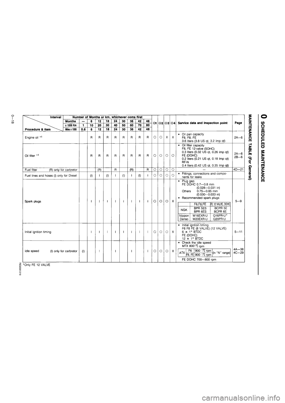
Interval
Procedure & item
Number of Months or km, whichever corns first
Months
x 1000 Km
Miles x 1000
Engine oil
Oil filter
Fuel filter (R) only for carbretor
Fuel lines and hoses (I) only for Diesel
Spark plugs
Initial ignition timing
Idle speed (I) only for carbretor
0.6
(I)
6
10
(0
12
20
12
(R)
18
30
18
(I)
24
40
24
30
50
30
(I)
36
60
36
(R)
42
70
42
(I)
48
80
48
®1
O
o
o
o
o
o
o
©2
O
o
o
o
o
o
o
©3
O
o
o
o
o
o
©4
O
o
o
Service data and inspection point
Oil pan capacity F6, F8, FE 3.6 liters (3.8 US qt, 3.2 Imp qt)
Oil filter capacity F8, FE 12-valve (SOHC)
0.3 liters (0.32 US qt, 0.26 Imp qt)
FE (DOHC) 0.2 liters (0.21 US qt, 0.18 Imp qt) RF-N
0.4 liters (0.42 US qt, 0.35 Imp qt)
Fittings, connections and compo-
nents for leaks
Plug gap FE DOHC 0.7—0.8 mm (0.028-0.031 in) Others 0.75—0.85 mm (0.030—0.033 in) Recommended spark plugs
F6,F8,FE FE
12 VALVE,
DOHC
NGK BPR 5ES BPR 6ES BCPR 5E
BCPR 6E
Nippon
Denso W16EXR-U
W20EXR-U
Q16PR-U* Q20PR-U
Initial ignition timing F6 F8 FE (8 VALVE) (12 VALVE)
6 ±
1
° BTDC FE (DOHC) 12 ± 1° BTDC
Check the idle speed
MTX 80015? rpm
ATX F6 900 rpm (in "N" range) ATX F8, FE 900 t5? rpm (in "N" range)
FE DOHC 700—800 rpm
§ *Only FE 12 VALVE
Page
2A—6
2A-6
2B-6
4D—21
5-9
5-11
4A—38
4C-29
m z >
z o m
H >
CD I-m
T1
o
o
m z >
z o m
Page 58 of 1865

1 A ON-VEHICLE MAINTENANCE (VALVE SEAL)
VALVE SEAL
Removal
1. Disconnect the negative battery cable.
2. Drain the engine coolant.
3. Remove in the sequence shown in the figure referring to the removal note for specially marked parts.
76G01A-114
11. Fuel hose (carb.)
12. Rear housing
13. Rocker arm and shaft assembly
14. Camshaft cap (12-valve)
15. Camshaft
16. Valve keeper
17. Upper valve spring seat
18. Valve spring
19. Lower valve spring seat
20. Valve seal
1. Air cleaner assembly (carb.)
2. Air intake pipe (Fl)
3. High-tension lead and spark plug
4. Upper timing belt cover
5. Timing belt
6. Cylinder head cover
7. Camshaft pulley
8. Front housing
9. Distributor
10. Upper radiator hose
1A—26
Page 218 of 1865

1C TUNE-UP PROCEDURE
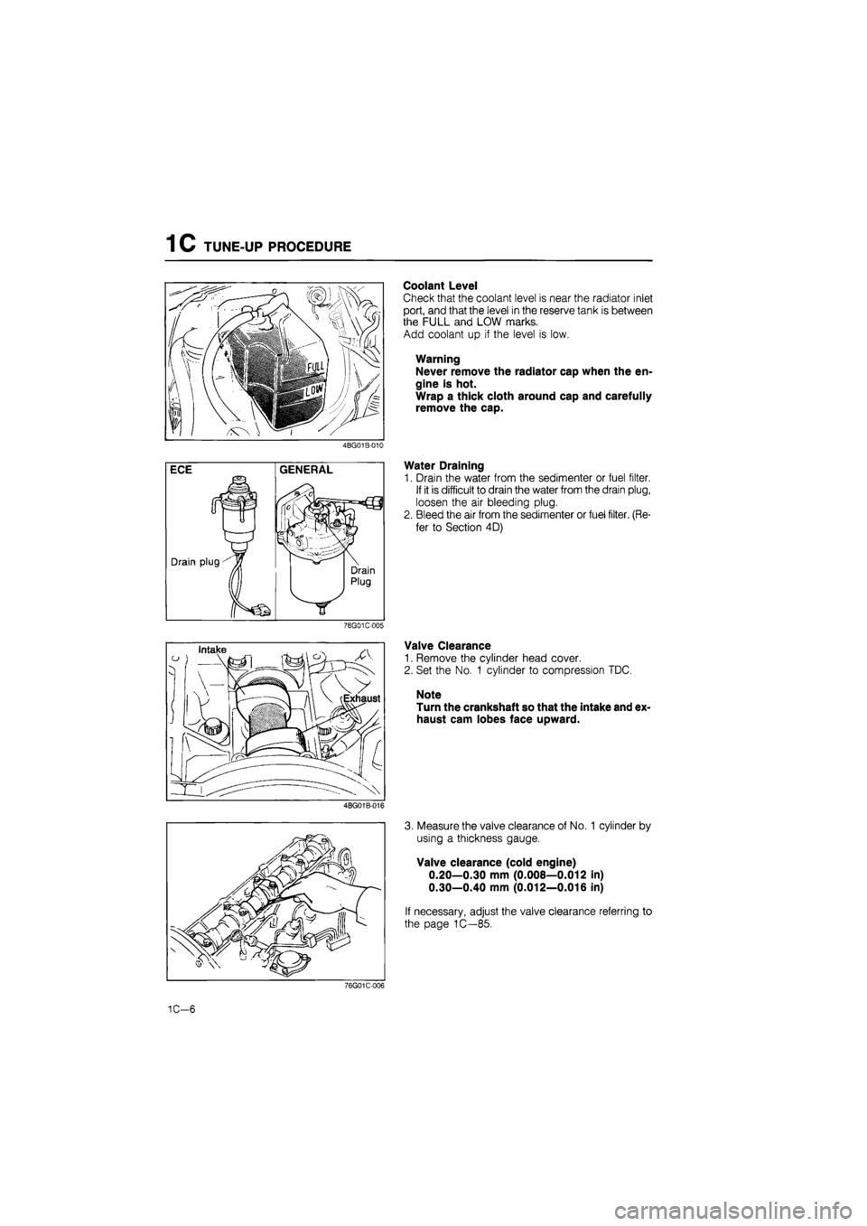
Coolant Level
Check that the coolant level is near the radiator inlet
port, and that the level in the reserve tank is between
the FULL and LOW marks.
Add coolant up if the level is low.
Warning
Never remove the radiator cap when the en-
gine is hot.
Wrap a thick cloth around cap and carefully
remove the cap.
4BG01B-010
Water Draining
1. Drain the water from the sedimenter or fuel filter.
If it is difficult to drain the water from the drain plug,
loosen the air bleeding plug.
2. Bleed the air from the sedimenter or fuel filter. (Re-
fer to Section 4D)
76G01C-005
Valve Clearance
1. Remove the cylinder head cover.
2. Set the No. 1 cylinder to compression TDC.
Note
Turn the crankshaft so that the intake and ex-
haust cam lobes face upward.
4BG01B-016
3. Measure the valve clearance of No. 1 cylinder by
using a thickness gauge.
Valve clearance (cold engine)
0.20—0.30 mm (0.008—0.012 in)
0.30—0.40 mm (0.012—0.016 in)
If necessary, adjust the valve clearance referring to
the page 1C—85.
76G01C-006
1C-6
Page 222 of 1865

1C ON-VEHICLE INSPECTION
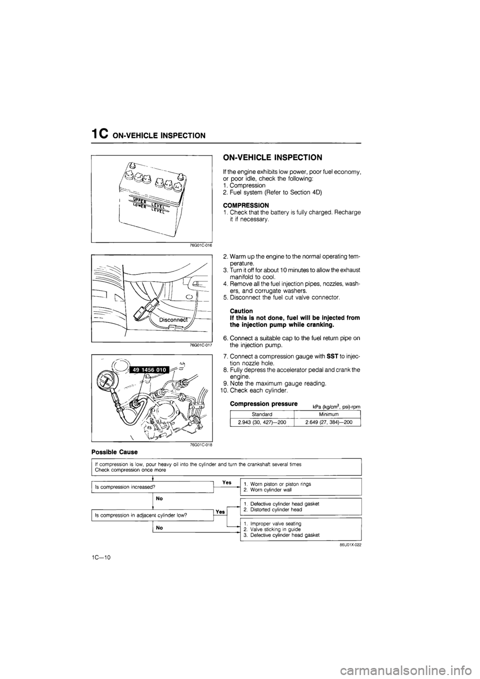
ON-VEHICLE INSPECTION
If the engine exhibits low power, poor fuel economy,
or poor idle, check the following:
1. Compression
2. Fuel system (Refer to Section 4D)
COMPRESSION
1. Check that the battery is fully charged, Recharge
it if necessary.
76G01C-016
76G01C-017
2. Warm up the engine to the normal operating tem-
perature.
3. Turn it off for about 10 minutes to allow the exhaust
manifold to cool.
4. Remove all the fuel injection pipes, nozzles, wash-
ers, and corrugate washers.
5. Disconnect the fuel cut valve connector.
Caution
If this is not done, fuel will be injected from
the injection pump while cranking.
6. Connect a suitable cap to the fuel return pipe on
the injection pump.
7. Connect a compression gauge with SST to injec-
tion nozzle hole.
8. Fully depress the accelerator pedal and crank the
engine.
9. Note the maximum gauge reading.
10. Check each cylinder.
Compression pressure kPa (kg/cm2, psi)-rpm
Standard Minimum
2.943 (30, 427)—200 2.649 (27, 384)—200
76G01C-018
Possible Cause
86U01X-022
1C-10
Page 252 of 1865

1 C DISASSEMBLY (CYLINDER HEAD)
CYLINDER HEAD
76G01C-079
1. Thermostat cover
2. Thermostat
3. Thermostat case
4. Front and rear engine
hanger
5. Fuel leak pipe
6. Injection nozzle
7. Glow cord
8. Glow plug
9. Camshaft cap
10. Oil seal
11. Camshaft
12. Cylinder head bolt
13. Cylinder head and gasket
14. Tappet and adjusting disc
15. Valve keepers
16. Upper spring seat
17. Valve spring
18. Valve
19. Lower spring seat
20. Valve seal
21. Valve guide and clip
1C-40
Page 380 of 1865

OUTLINE 4A
SPECIFICATIONS
F6 & F8 Engine
Engine F6 F8
Specification General Singapore General
ECE,
Hong Kong, &
Singapore
Idle speed
rpm
MTX 800
+58
Idle speed
rpm
ATX 950
t5§
(in N range)|
900 +5§ (in N
range)
CO concentration
%
2.0
± 0.5
(Without secondary
air
injection)
Carburetor
Type Down draft, two barrel
Throat diameter
mm (in)
Primary 30 (1.18) Throat diameter
mm (in)
Secondary 34 (1.34)
Venturi diameter
mm
(in) Primary 23.5 (0.93) Venturi diameter
mm
(in) Secondary 29.0 (1.14)
Main nozzle
mm (in)
Primary 2.6 (0.10) Main nozzle
mm (in)
Secondary 2.8 (0.11)
Main
jet mm (in)
Primary MTX 1.10 (0.0433) 1.09 (0.0429) 1.14 (0.045)
Main
jet mm (in)
Primary ATX 1.10 (0.0433) 1.08 (0.0425) 1.12 (0.044) Main
jet mm (in)
Secondary 1.50 (0.059)
Main
air
bleed mm (in)
Primary MTX 0.60 (0.024) 0.60 (0.024) 0.55 (0.022) Main
air
bleed mm (in)
Primary ATX 0.60 (0.024) 0.80 (0.031) 0.60 (0.024) Main
air
bleed mm (in) Secondary 0.50 (0.020)
Slow
jet mm (in)
Primary 0.48 (0.019) 0.46 (0.018) Slow
jet mm (in)
Secondary 1.00 (0.039) 1.10 (0.043)
Slow
air
bleed mm (in)
Primary No.1 0.80 (0.031)
Slow
air
bleed mm (in)
Primary No.2 1.90 (0.075) Slow
air
bleed mm (in) Secondary No.1 1.00 (0.039) 0.80 (0.031) Slow
air
bleed mm (in) Secondary No.2 0.50 (0.020)
Power
jet mm (in)
0.50 (0.0201
Fast idle adjustment
mm (in)
Clearance between
Drimarv
throttle valve and bore
1.40-1.76 (0.055—0.069) MTX: 0.48-0.64 (0.019-0.025) ATX: 0.56-0.72 (0.022-0.028)
Float level adjustment mm (in)
Max. fuel flow
"L"
Clearance between
flo
44 (17.3)
at and
air
horn without aasket Float level adjustment mm (in) Fuel stop
"H"
12.5(0.49)
Clearance between float and
air
horn without aasket; float lowered
by
own weight
Choke breaker diaphragm mmHg (inHg)
Start 180-240 (7.1—9.5) 100-160 (3.9—6.3) Choke breaker diaphragm mmHg (inHg) Stop 290-350 (11.4—13.8) 220—280 8.7—11.01
Choke opener mmHg (inHg) Start 35-65 (1.4-2.6)
...
35-65 (1.4-2.6) Choke opener mmHg (inHg) Stop
......
130-190 (5.1-7.5) 130-190 (5.1-7.5)
Fuel tank capacity
Liters (US gal, Imp gal) 60 (15.9, 13.2)
Fuel Dump
Delivery pressure kPa (kg/cm2,
psi)
20-26 (0.20-0.27, 2.8—3.8)
Feeding capacity cc/min (cu in/min) More than 860 (52.5)
at
idle
Fuel filter
Type Paper element with magnet
Air cleaner
Fresh-Hot switching Manual Diaphragm type
Element tvoe Oil permeated paper
Fuel specification Leaded regular
76G04A-513
4 A—15
Page 381 of 1865

4A OUTLINE
FE Engine
Engine FE 8Valve FE 12Valve FE 8Valve
Specification General Middle East
ECE, Hong Kong, & Singapore Unleaded fuel
Idle speed
rpm
MTX 800
+5§
850
+5§
Idle speed
rpm
ATX 900
+58 (in N
range)
CO concentration
%
2.0
± 0.5
(Without secondary
air
injection)
Carburetor
Type Down draft,
two
barrel
Throat diameter
mm (in)
Primary 30 (1.18) Throat diameter
mm (in)
Secondary 34 (1.34)
Venturi diameter
mm (in)
Primary 23.5 (0.93) Venturi diameter
mm (in)
Secondary 29.0 (1.14)
Main nozzle
mm (in)
Primary 2.6 (0.10) Main nozzle
mm (in)
Secondary 2.8 (0.11)
Main
jet mm (in)
Primary MTX 1.14 (0.045) 1.09 (0.0429) 1.14 (0.045) 1.09 (0.0429) Main
jet mm (in)
Primary ATX 1.12 (0.044) 1.08 (0.0425) 1.12 (0.044) 1.09 (0.0429) Main
jet mm (in)
Secondary 1.55 (0.061) 1.50 (0.059) 1.55 (0.061) 1.50 (0.059)
Main
air
bleed
mm (in)
Primary MTX 0.50 (0.020) 0.60(0.024) 0.50 (0.020) 0.50 (0.020) Main
air
bleed
mm (in)
Primary ATX 0.55 (0.022) 0.80 (0.031) 0.55 (0.022) 0.50 (0.020) Main
air
bleed
mm (in) Secondary 0.50 (0.020)
Slow
jet mm (in)
Primary 0.46 (0.018)
Slow
jet mm (in)
Secondary MTX 1.10 (0.043) 1.00 (0.039) 1.10 (0.043) 0.90 (0.035) Slow
jet mm (in)
Secondary ATX 1.10 (0.043) 1.00 (0.039) 1.10 (0.043) 1.00 (0.039)
Slow
air
bleed
mm (in)
Primary No.1 0.80 (0.031)
Slow
air
bleed
mm (in)
Primary No.2 1.90 (0.075) Slow
air
bleed
mm (in) Secondary No.1 0.80 (0.031) 1.00 (0.039) 0.80 (0.031) 1.00 (0.039)
Slow
air
bleed
mm (in) Secondary No.2 0.50 (0.020)
Power
jet mm (in)
MTX 0.50 (0.020) 0.50 (0.020) Power
jet mm (in)
ATX 0.50 (0.020) 0.40 (0.016)
Fast idle adjustment
mm (in)
Clearance between primary throttle valve and bore
MTX 0.48—0.64
(0.019-0.025) 1.40—1.76
(0.055-0.069)
0.48—0.64
(0.019-0.025) 1.40-1.76
(0.055-0.069)
Fast idle adjustment
mm (in)
Clearance between primary throttle valve and bore ATX 0.56-0.72 (0.022—0.028)
1.40—1.76
(0.055-0.069) 0.56-0.72 (0.022—0.028)
1.40-1.76
(0.055-0.069)
Float level adjust-
ment
mm (in)
Max. fuel flow
"L"
Clearance between
flo
44 (17.3)
at and
air
horn without aasket Float level adjust-
ment
mm (in)
Fuel stop
"H" |
12.5(0.49)
Clearance between float and
air
horn without aasket: float lowered
bv
own weiaht
Choke breaker diaphragm mm-Hg (in-Hg)
Start 100-160 (3.9—6.3) 180—240 (7.1-9.4) 100-160
(3.9-6.3)
180-240
(7.1-9.4) Choke breaker diaphragm mm-Hg (in-Hg) Stop 220—280
(8.7-11.0)
290-350
(11.4-13.8)
220—280
(8.7-11.0)
290-350
(11.4-13.8)
Choke opener mmHg (inHg)
Start 80—120
(3.1-8.7)
30-70 (1.2-2.8) Choke opener mmHg (inHg)
Stop 220-280 (8.7—11.0) 130-190
(5.1-7.5)
Fuel tank capacity
Liters (US aal, Imp aal) 60 (15.9, 13.2)
Fuel DumD
Delivery pressure kPa (kg/cm2,
psi)
20-26 (0.20—0.27, 2.8-3.8) 20-29 (0.20-0.30, 2.8-4.3)
20-26 (0.20-0.27, 2.8-3.8)
Feedina caDacitv cc/min
feu
in/mini More than 860 (52.5)
at
idle
Fuel filter
Type Paper element with magnet
Air cleaner
Fresh-Hot switchina Diaphragm Manual Diaphragm Bimetal
Element
tvDe
Oil permeated paper
Fuel specification Leaded super
Unleaded super Leaded regular Leaded super Unleaded super Unleaded regular
76G04G-514
4A—16
Page 403 of 1865

4A
IDLE
SPEED AND
IDLE
MIXTURE
76G04A-059
76G04A-060
76G04A-061
IDLE
SPEED AND IDLE MIXTURE
ADJUSTMENT
Note
a) Before adjusting the idle speed and idle
mixture, be sure the ignition timing, spark
plugs, carburetor float level, etc., are all in
normal operation condition.
b)Turn off all electrical loads.
c) This adjustment must be done while the fan
motor is not operating.
Idle Speed
1. Connect a tachometer to the engine.
2. Warm up the engine, and check that the choke
valve has fully opened.
3. Check the idle speed.
Specification
MTX ATX (in N range)
Specification Others
FE 8Valve Unleaded fuel F6 F8 & FE
Idle speed rpm 800 +6S 850 +5S 950 +5o° 900 +5§
4. If not within specification, adjust the idle speed by
turning the throttle adjust screw.
Caution
After adjusting the idle speed, the dashpot ad-
justment should be checked and adjusted if
necessary.
Idle Mixture
[Except FE 8Valve—Unleaded Fuel]
Adjust the idle mixture as follows, after adjusting the
idle speed.
1. Disconnect the secondary air hoses from the reed
valves and plug them. (If equipped.)
2. Insert an exhaust gas analyzer into the tail pipe and
measure the CO concentration.
CO concentration: 2.0 ± 0.5%
3. If not within the specification, remove the blind cap
from the mixture adjust screw.
76G04A-062
4A—38