ground clearance MAZDA 626 1987 Workshop Manual
[x] Cancel search | Manufacturer: MAZDA, Model Year: 1987, Model line: 626, Model: MAZDA 626 1987Pages: 1865, PDF Size: 94.35 MB
Page 746 of 1865

5 STARTER (GASOLINE ENGINE, 0.85, 0.95 KW TYPE)
4BG05X-078
4BG05X-079
4BG05X-080
Drive Pinion
Remove the stopper for the overrunning clutch by us-
ing a pipe as shown in the figure.
Adjustment of Pinion Gap
1. Disconnect the wiring from terminal (M).
2. Apply battery power to the terminal (S) and ground
the starter motor body, the pinion will eject outward
and then stop.
3. Measure the clearance (pinion gap) between the
pinion and the stopper.
Pinion gap: 0.5—2.0 mm (0.020—0.079 in)
Caution
Do not let electricity flow continuously for
more than 10 seconds.
If the pinion gap is not within the specified range,
make the adjustment by increasing or decreasing
the number of washers used between the magnetic
switch and the drive housing. The gap will become
smaller if the number of washers is increased.
Caution
Do not use the washers
(0.079 in) in all.
more than 2 mm
INSPECTION
Armature Coil
1. Ground of the armature coil
(1) Check for continuity between the commutator
and the core by using a circuit tester.
(2) Replace the armature if there is continuity.
4BG05X-081
5—40
Page 777 of 1865

STARTER (DIESEL ENGINE, 2.2 KW TYPE) 5
4BG05X-113
4BG05X-080
Adjustment of pinion gap
1. Disconnect the wiring from terminal (M).
2. Apply battery power to the terminal (S) and ground
the starter motor body, the pinion will eject outward
and then stop.
3. Measure the clearance (pinion gap) between the
pinion and the stopper.
Note
Be careful not to let electricity flow continu-
ously for more than 10 seconds.
Pinion gap: 0.5—2.0 mm (0.020—0.079 in)
4. If the pinion gap is not within the specified range,
make the adjustment by increasing or decreasing
the number of washers used between the magnetic
switch and the drive housing. The gap will become
smaller if the number of washers is increased.
Caution
Do not use the washers more than plates.
INSPECTION
Armature Coil
1. Ground of the armature coil
Check for continuity between the commutator and
the core by using a circuit tester. Replace the ar-
mature if there is continuity.
4BG05-081
2. Vibration of the commutator
Plate the armature on V blocks, and measure the
vibration by using a dial gauge. If the vibration is
Limit or more, repair so that is standard by using
a lathe, or replace the armature.
Standard vibration: 0.05 mm (0.002 in)
Limit: 0.4 mm (0.018 in)
Note
Before checking, be sure than there is no play
in the bearings.
4BG05X-Q82
5-71
Page 1468 of 1865

1 1 ANTI-LOCK BRAKE SYSTEM (ABS)
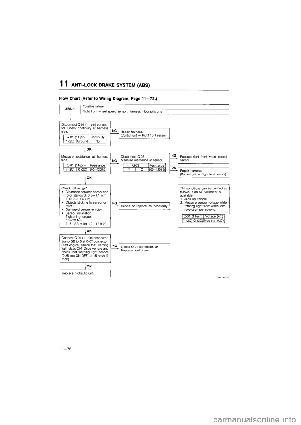
Flow Chart (Refer to Wiring Diagram, Page 11—72.)
ABS-1
Possible failure
Right front wheel speed sensor, Harness, Hydraulic unit
Disconnect Q-01 (11-pin) connec-tor. Check continuity
at
harness side.
Q-01 (11-pin)
I
Continuity
Y (2C) Ground No
OK
Measure resistance
at
harness side.
Q-01 (11-pin) Resistance
Y (2C)
i 0
(2D) 800—1200
Q
OK
NG
Repair harness.
(Control unit — Right front sensor)
NG
Disconnect Q-03. Measure resistance
at
sensor.
Q-03 Resistance
Y
[ O
800—1200 Q
NG
Replace right front wheel speed sensor.
OK
Repair harness.
(Control unit — Right front sensor)
Check followings*
• Clearance between sensor and rotor standard: 0.3—1.1
mm
(0.012-0.043
in)
• Objects sticking
to
sensor
or
rotor
• Damaged sensor
or
rotor
• Sensor installation Tightening torque: 16-23 N-m (1.6-2.3 m-kg, 12—17 ft-lb)
OK
Connect Q-01 (11-pin) connector. Jump GB
to B at
Q-07 connector. Start engine. Check that warning light stays ON. Drive vehicle and check that warning light flashes (0.25 sec ON OFF)
at 15
km/h
(9
mph).
NG
Repair
or
replace
as
necessary
* All conditions can
be
verified
as
follows,
if an AC
voltmeter
is
available. 1. Jack
up
vehicle. 2. Measure sensor voltage while rotating right front wheel
one
revolution
per
second.
Q-01 (11-Din) Voltage (AC)
Y (2C) O (2D) More than 0.25V
NG
Check Q-01 connector,
or
Replace control unit.
OK
Replace hydraulic unit.
76G11X-055
11—76
Page 1469 of 1865

ANTI-LOCK BRAKE SYSTEM (ABS) 1 1
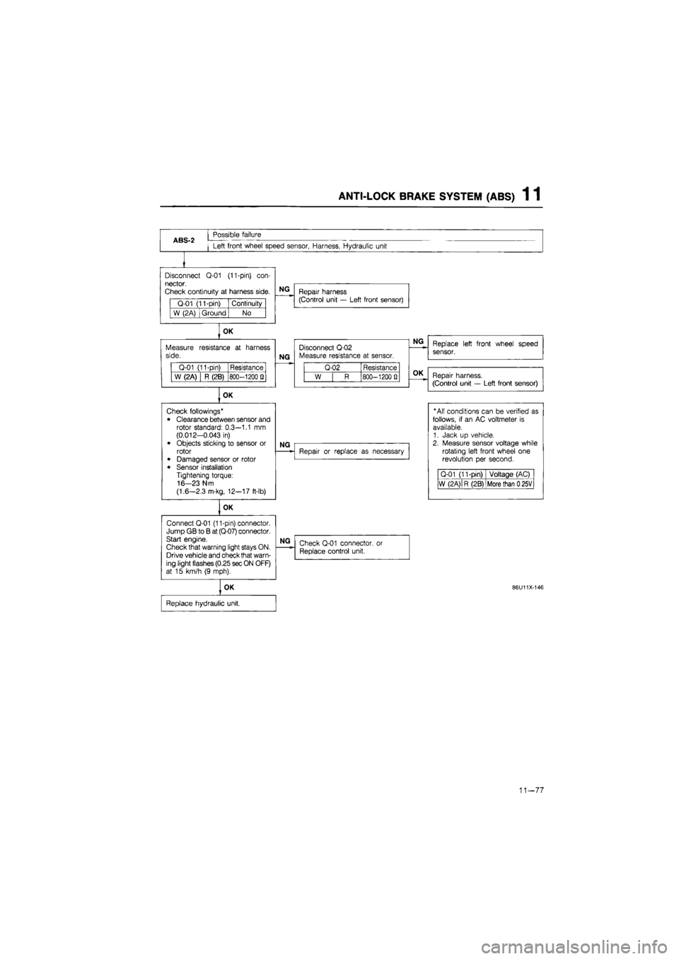
ABS-2
Possible failure
Left front wheel speed sensor, Harness, Hydraulic unit
Disconnect
Q-01
(11-pin)
con-
nector.
Check continuity
at
harness side.
Q-01 (11-pin) Continuity
W (2A) Ground No
OK
Measure side.
Q-01 (11-pin) Resistance
W (2A) R (2B) 800-1200
fl
OK
Connect Q-01 (11-pin) connector. Jump GB
to B
at (Q-07) connector. Start engine.
Check that warning light stays ON. Drive vehicle and check that warn-ing light flashes (0.25 sec ON OFF) at
15
km/h
(9
mph).
NG
Repair harness (Control unit
—
Left front sensor)
resistance
at
harness
NG
Disconnect Q-02 Measure resistance
at
sensor.
Q-02 Resistance
W
| R
800-1200
0
OK
Check followings*
• Clearance between sensor and rotor standard: 0.3—1.1
mm
(0.012-0.043
in)
• Objects sticking
to
sensor
or
rotor • Damaged sensor
or
rotor
• Sensor installation Tightening torque: 16-23 N m
(1.6—2.3 m-kg, 12-17 ft-lb)
NG
OK
NG
Repair
or
replace
as
necessary
NG
Check Q-01 connector,
or
Replace control unit.
OK
Replace hydraulic unit.
Replace left front wheel speed
sensor.
Repair harness.
(Control unit
—
Left front sensor)
"All conditions can
be
verified
as
follows,
if an AC
voltmeter
is
available. 1. Jack
up
vehicle. 2. Measure sensor voltage while rotating left front wheel
one
revolution
per
second.
Q-01 (11-pin) Voltage (AC)
W (2 A)
|
R (2B) More than
0
25V
86U11X-146
11-77
Page 1470 of 1865

1 1 ANTI-LOCK BRAKE SYSTEM (ABS)
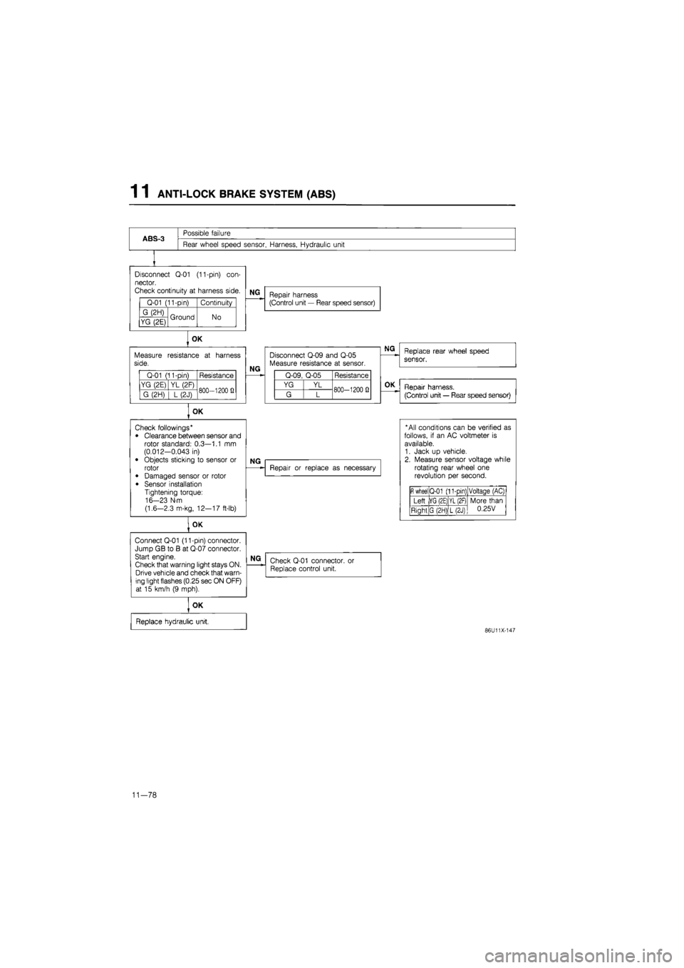
ABS-3
Possible failure
Rear wheel speed sensor, Harness, Hydraulic unit
Disconnect
Q-01
(11-pin)
con-
nector.
Check continuity
at
harness side.
Q-01 (11-pin) Continuity
G (2H) Ground No YG (2E) Ground No
Measure side.
Q-01 (11-pin) Resistance
YG (2E) YL (2F) 800—1200
fi
G (2H)
] L
(2J) 800—1200
fi
OK
Connect Q-01 (11-pin) connector. Jump GB
to B at
Q-07 connector. Start engine.
Check that warning light stays ON. Drive vehicle and check that warn-ing light flashes (0.25 sec ON OFF) at
15
km/h
(9
mph).
NG
Repair harness (Control unit
—
Rear speed sensor)
OK
resistance
at
harness
NG
Disconnect Q-09 and Q-05 Measure resistance
at
sensor.
Q-09, Q-05 Resistance
YG YL 800-1200
0
G L 800-1200
0
OK
Check followings* • Clearance between sensor and rotor standard: 0.3—1.1
mm
(0.012-0.043
in)
• Objects sticking
to
sensor
or
rotor
• Damaged sensor
or
rotor
• Sensor installation Tightening torque: 16-23 N-m
(1.6—2.3 m-kg, 12—17 ft-lb)
NG
Repair
or
replace
as
necessary
NG
Check Q-01 connector. Replace control unit.
or
OK
Replace hydraulic unit,
Replace rear wheel speed
sensor.
OK
Repair harness.
(Control unit
—
Rear speed sensor)
* All conditions can
be
verified
as
follows,
if an AC
voltmeter
is
available. 1. Jack
up
vehicle. 2. Measure sensor voltage while rotating rear wheel
one
revolution
per
second.
fi
wheel Q-01 (11-pin) Voltaqe (AC)
Left |YG (2E) YL (2F) More than 0.25V Right G (2H) L(2J)
More than 0.25V
86U11X-147
11-78
Page 1796 of 1865

COMPRESSOR 16
69G16X-026
M10X1.25^45
Low-pressure x pressure
hose hose Compressor
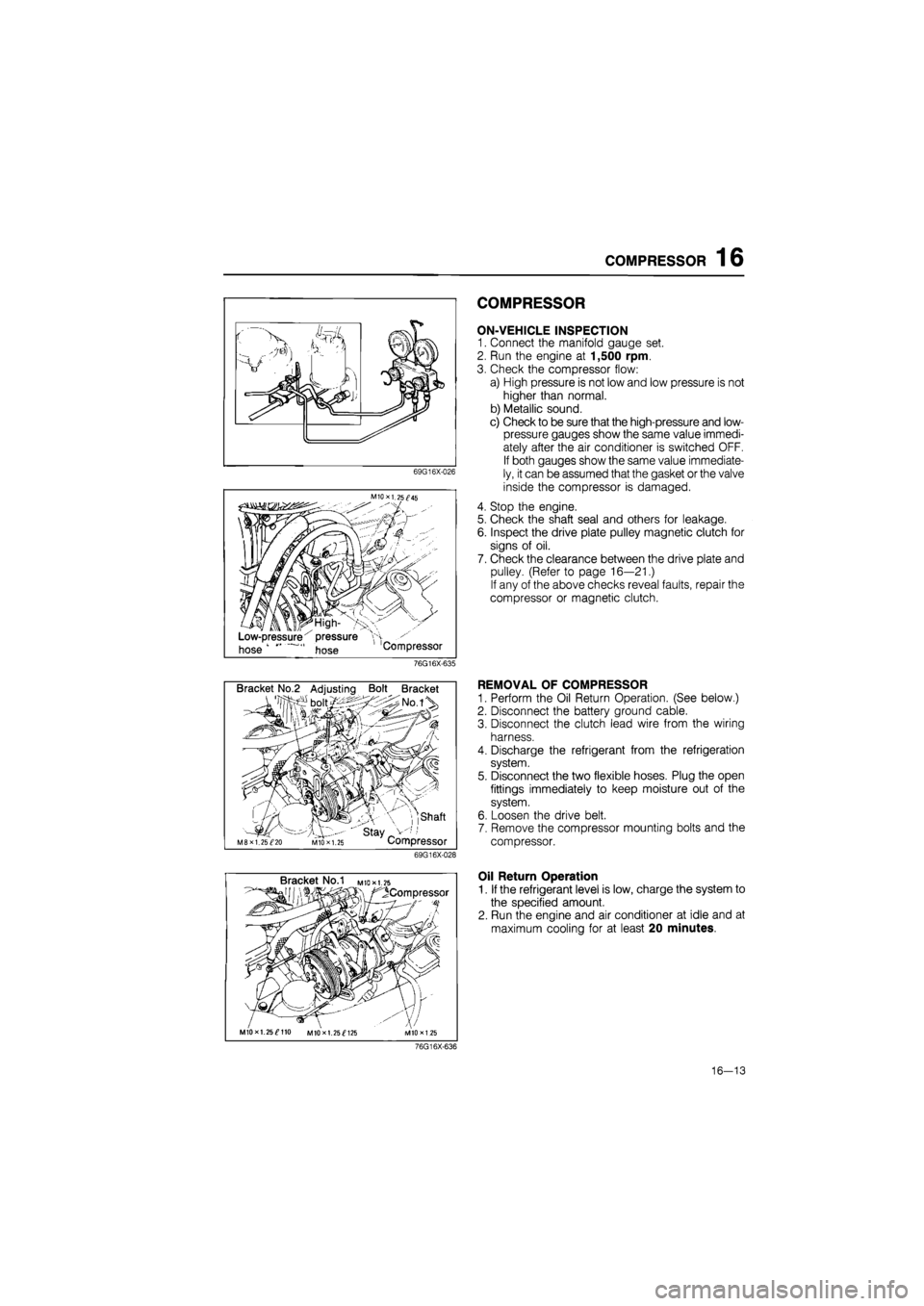
COMPRESSOR
ON-VEHICLE INSPECTION
1. Connect the manifold gauge set.
2. Run the engine at 1,500 rpm.
3. Check the compressor flow:
a) High pressure is not low and low pressure is not
higher than normal.
b) Metallic sound.
c) Check to be sure that the high-pressure and low-
pressure gauges show the same value immedi-
ately after the air conditioner is switched OFF.
If both gauges show the same value immediate-
ly, it can be assumed that the gasket or the valve
inside the compressor is damaged.
4. Stop the engine.
5. Check the shaft seal and others for leakage.
6. Inspect the drive plate pulley magnetic clutch for
signs of oil.
7. Check the clearance between the drive plate and
pulley. (Refer to page 16—21.)
If any of the above checks reveal faults, repair the
compressor or magnetic clutch.
76G16X-635
Bracket No.2 Adjusting Bolt Bracket
, ,shaft
' stay _ M8XI. 25^20 MIO X 1.25 Compressor
69G16X-028
REMOVAL OF COMPRESSOR
1. Perform the Oil Return Operation. (See below.)
2. Disconnect the battery ground cable.
3. Disconnect the clutch lead wire from the wiring
harness.
4. Discharge the refrigerant from the refrigeration
system.
5. Disconnect the two flexible hoses. Plug the open
fittings immediately to keep moisture out of the
system.
6. Loosen the drive belt.
7. Remove the compressor mounting bolts and the
compressor.
Bracket No.1 M
to* 1.25
^Compressor
MIOxl. 25^110 MIOxl. 25^125
Oil Return Operation
1. If the refrigerant level is low, charge the system to
the specified amount.
2. Run the engine and air conditioner at idle and at
maximum cooling for at least 20 minutes.
76G16X-636
16—13