heater MAZDA 626 1987 Workshop Manual
[x] Cancel search | Manufacturer: MAZDA, Model Year: 1987, Model line: 626, Model: MAZDA 626 1987Pages: 1865, PDF Size: 94.35 MB
Page 14 of 1865
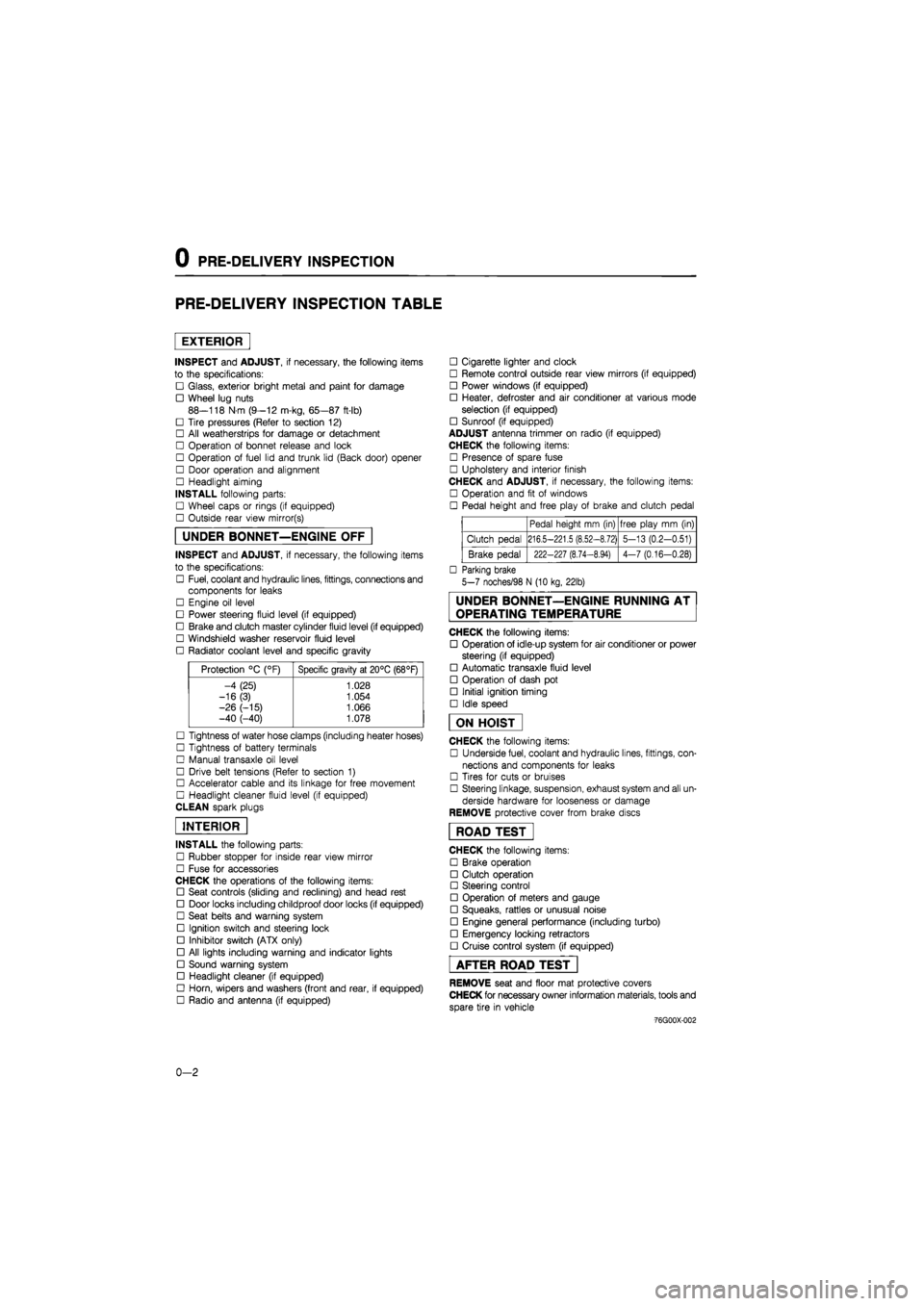
0 PRE-DELIVERY INSPECTION
PRE-DELIVERY INSPECTION TABLE
EXTERIOR
INSPECT and ADJUST, if necessary, the following items
to the specifications:
• Glass, exterior bright metal and paint for damage
• Wheel lug nuts
88—118 N m (9—12 m-kg, 65—87 ft-lb)
• Tire pressures (Refer to section 12)
• All weatherstrips for damage or detachment
• Operation of bonnet release and lock
• Operation of fuel lid and trunk lid (Back door) opener
• Door operation and alignment
• Headlight aiming
INSTALL following parts:
• Wheel caps or rings (if equipped)
• Outside rear view mirror(s)
UNDER BONNET—ENGINE OFF
INSPECT and ADJUST, if necessary, the following items
to the specifications:
• Fuel, coolant and hydraulic lines, fittings, connections and
components for leaks
• Engine oil level
• Power steering fluid level (if equipped)
• Brake and clutch master cylinder fluid level (if equipped)
• Windshield washer reservoir fluid level
• Radiator coolant level and specific gravity
Protection °C (°F) Specific gravity at 20°C (68°F)
-4 (25) 1.028
-16(3) 1.054
-26 (-15) 1.066 -40 (-40) 1.078
• Tightness of water hose clamps (including heater hoses)
• Tightness of battery terminals
• Manual transaxle oil level
• Drive belt tensions (Refer to section 1)
• Accelerator cable and its linkage for free movement
• Headlight cleaner fluid level (if equipped)
CLEAN spark plugs
INTERIOR
INSTALL the following parts:
• Rubber stopper for inside rear view mirror
• Fuse for accessories
CHECK the operations of the following items:
• Seat controls (sliding and reclining) and head rest
• Door locks including childproof door locks (if equipped)
• Seat belts and warning system
• Ignition switch and steering lock
• Inhibitor switch (ATX only)
• All lights including warning and indicator lights
• Sound warning system
• Headlight cleaner (if equipped)
• Horn, wipers and washers (front and rear, if equipped)
• Radio and antenna (if equipped)
• Cigarette lighter and clock
• Remote control outside rear view mirrors (if equipped)
• Power windows (if equipped)
• Heater, defroster and air conditioner at various mode
selection (if equipped)
• Sunroof (if equipped)
ADJUST antenna trimmer on radio (if equipped)
CHECK the following items:
• Presence of spare fuse
• Upholstery and interior finish
CHECK and ADJUST, if necessary, the following items:
• Operation and fit of windows
• Pedal height and free play of brake and clutch pedal
Pedal height mm (in) free play mm (in)
Clutch pedal 216.5-221.5 (8.52-8.72) 5-13 (0.2-0.51)
Brake pedal 222-227 (8.74-8.94) 4-7 (0.16-0.28)
• Parking brake
5-7 noches/98 N (10 kg, 22lb)
UNDER BONNET—ENGINE RUNNING AT
OPERATING TEMPERATURE
CHECK the following items:
• Operation of idle-up system for air conditioner or power
steering (if equipped)
• Automatic transaxle fluid level
• Operation of dash pot
• Initial ignition timing
• Idle speed
ON HOIST
CHECK the following items:
• Underside fuel, coolant and hydraulic lines, fittings, con-
nections and components for leaks
• Tires for cuts or bruises
• Steering linkage, suspension, exhaust system and all un-
derside hardware for looseness or damage
REMOVE protective cover from brake discs
ROAD TEST"
CHECK the following items:
• Brake operation
• Clutch operation
• Steering control
• Operation of meters and gauge
• Squeaks, rattles or unusual noise
• Engine general performance (including turbo)
• Emergency locking retractors
• Cruise control system (if equipped)
AFTER ROAD TEST
REMOVE seat and floor mat protective covers
CHECK for necessary owner information materials, tools and
spare tire in vehicle
-76G00X-002
0-2
Page 53 of 1865

1 A ON-VEHICLE MAINTENANCE (CYLINDER HEAD)
1. High-tension lead and spark plug
2. Accelerator cable
3. Throttle cable (ATX)
4. Air intake pipe (Fl)
5. Air cleaner assembly (carb.)
6. Fuel hose
7. Fuel pump (carb.)
8. Upper radiator hose
9. Heater hose
10. Brake vacuum hose
11. Canister hose (Fl, Middle East)
12. Three-way solenoid assembly
13. Engine harness connector and ground
14. Secondary air pipe assembly (except
General)
15. EGR pipe (Fl, Unleaded carb.)
16. Exhaust manifold insulator
17. Exhaust pipe
18. Exhaust manifold
19. Gusset plate (Fl)
20. Intake manifold bracket (Fl)
21. Intake manifold assembly
22. Distributor
23. A/C compressor and bracket
24. Upper timing belt cover
25. Timing belt tensioner spring
26. Timing belt
27. Cylinder head cover
28. Cylinder head and gasket 76G01A-031
Removal note
Fuel hose
Warning
a) Cover the hose with a rag because fuel will
spray out when disconnecting.
b) Keep sparks and open flame away from the
fuel area.
Plug the disconnected hoses to avoid fuel leakage.
Timing belt
1. Before removing the timing belt, turn the crankshaft
to align the mating mark of the camshaft pulley with
the front housing timing mark.
Note
For FE engine, align "2" mark.
For F8, F6 engine, align "3" mark.
2. Loosen the timing belt tensioner lock bolt.
3. Shift the tensioner outward as far as possible, then
temporarily tighten it.
1A—21
Page 67 of 1865
REMOVAL 1A
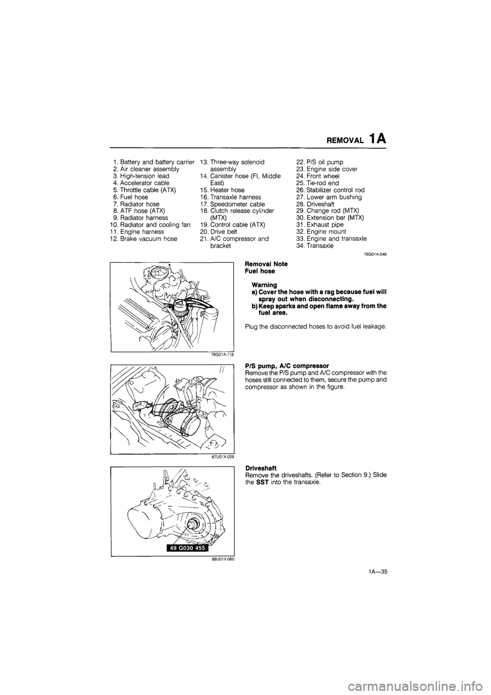
1. Battery and battery carrier 13. Three-way solenoid 22. P/S oil pump
2. Air cleaner assembly assembly 23. Engine side cover
3. High-tension lead 14. Canister hose (Fl, Middle 24. Front wheel
4. Accelerator cable East) 25. Tie-rod end
5. Throttle cable (ATX) 15. Heater hose 26. Stabilizer control rod
6. Fuel hose 16. Transaxle harness 27. Lower arm bushing
7. Radiator hose 17. Speedometer cable 28. Driveshaft
8. ATF hose (ATX) 18. Clutch release cylinder 29. Change rod (MTX)
9. Radiator harness (MTX) 30. Extension bar (MTX)
10. Radiator and cooling fan 19. Control cable (ATX) 31. Exhaust pipe
11. Engine harness 20. Drive belt 32. Engine mount
12. Brake vacuum hose 21. A/C compressor and 33. Engine and transaxle
bracket 34. Transaxle
76G01A-046
Removal Note
Fuel hose
Warning
a) Cover the hose with a rag because fuel will
spray out when disconnecting.
b) Keep sparks and open flame away from the
fuel area.
Plug the disconnected hoses to avoid fuel leakage.
76G01A-11E
P/S pump, A/C compressor
Remove the P/S pump and A/C compressor with the
hoses still connected to them, secure the pump and
compressor as shown in the figure.
67U01X-029
Driveshaft
Remove the driveshafts. (Refer to Section 9.) Slide
the SST into the transaxle.
86U01X-060
1A—35
Page 129 of 1865
INSTALLATION 1A
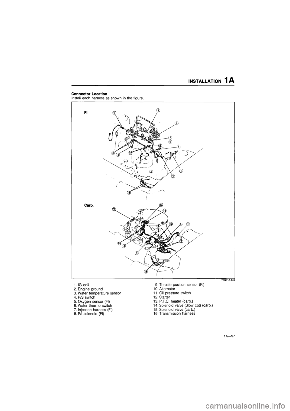
Connector Location
Install each harness as shown in the figure.
1. IG coil
2. Engine ground
3. Water temperature sensor
4. P/S switch
5. Oxygen sensor (Fl)
6. Water thermo switch
7. Injection harness (Fl)
8. F/l solenoid (Fl)
76G01A-146
9. Throttle position sensor (Fl)
10. Alternator
11. Oil pressure switch
12. Starter
13. P.T.C. heater (carb.)
14. Solenoid valve (Slow cot) (carb.)
15. Solenoid valve (carb.)
16. Transmission harness
1A—97
Page 130 of 1865
1A INSTALLATION
76G01A-147
86U01X-199
86U01X-200
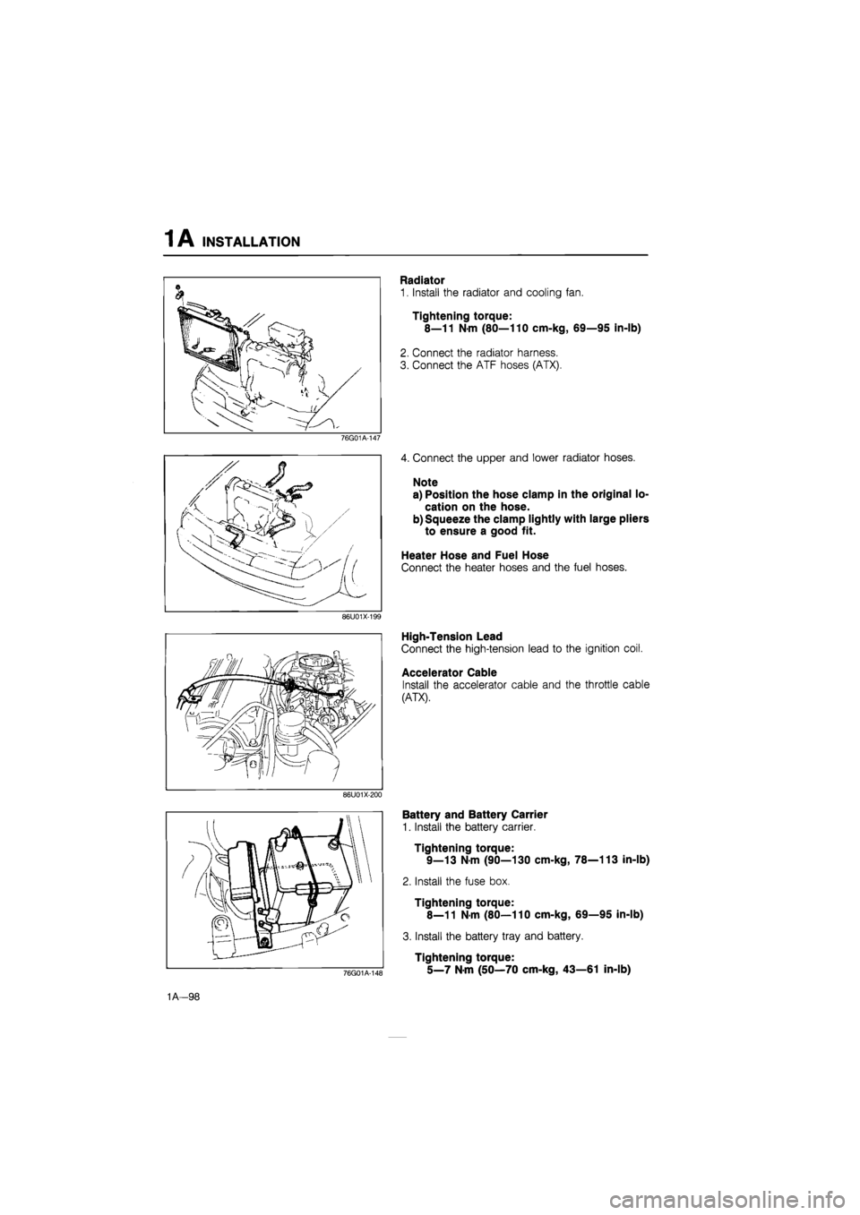
Radiator
1. Install the radiator and cooling fan.
Tightening torque:
8—11 N-m (80—110 cm-kg, 69—95 in-lb)
2. Connect the radiator harness.
3. Connect the ATF hoses (ATX).
4. Connect the upper and lower radiator hoses.
Note
a) Position the hose clamp in the original lo-
cation on the hose.
b) Squeeze the clamp lightly with large pliers
to ensure a good fit.
Heater Hose and Fuel Hose
Connect the heater hoses and the fuel hoses.
High-Tension Lead
Connect the high-tension lead to the ignition coil.
Accelerator Cable
Install the accelerator cable and the throttle cable
(ATX).
76G01A-148
Battery and Battery Carrier
1. Install the battery carrier.
Tightening torque:
9—13 N-m (90—130 cm-kg, 78—113 in-lb)
2. Install the fuse box.
Tightening torque:
8—11 N-m (80—110 cm-kg, 69—95 in-lb)
3. Install the battery tray and battery.
Tightening torque:
5_7 Nm (50—70 cm-kg, 43—61 in-lb)
1A—98
Page 148 of 1865

1 B ON-VEHICLE MAINTENANCE (CYLINDER HEAD)
1. Center cover
2. High-tension lead and spark plug
3. Accelerator cable
4. Air intake pipe assembly
5. Fuel hose
6. Upper radiator hose
7. Heater hose
8. Brake vacuum hose
9. Canister hose (Unleaded fuel)
10. Engine harness connector and ground
11. EGR pipe (Unleaded fuel)
12. A/C compressor and bracket
13. Exhaust manifold insulator
14. Exhaust pipe
15. Exhaust manifold
16. Intake manifold bracket
17. Intake manifold assembly
18. Distributor
19. Engine mount stay
20. Upper timing belt cover
21. Timing belt tensioner spring
22. Timing belt
23. Cylinder head cover
24. Cylinder head and gasket
76G01B-030
Removal note
Fuel hose
Warning
a) Cover the hose with a rag because fuel will
spray out when disconnecting.
b) Keep sparks and open flame away from the
fuel area.
Plug the disconnected hoses to avoid fuel leakage.
86U01X-032
Timing belt
1. Before removing the timing belt, turn the crankshaft
to align the mating marks of the camshaft pulleys
with the seal plate timing mark.
Note
For intake side camshaft pulley, align "I"
mark.
For exhaust side camshaft pulley, align "E"
mark.
76G01B-031
2. Loosen the timing belt tensioner lock bolt.
3. Shift the tensioner outward as far as possible, then
temporarily tighten it.
76G01B-034
1B—17
Page 154 of 1865

REMOVAL 1B
1. Battery and battery carrier
2. Air cleaner assembly
3. High-tension lead
4. Accelerator cable
5. Fuel hose
6. Radiator hose
7. Radiator harness
8. Radiator and electric fan
9. EGI harness
10. Engine harness
11. Brake vacuum hose
12. Canister hose (Unleaded
fuel)
13. Heater hose
14. Transaxle harness
15. Speedometer cable
16. Clutch release cylinder
17. Drive belt
18. A/C compressor and
bracket
19. P/S oil pump
20. Engine side cover
21. Front wheel
22. Tie-rod end
23. Stabilizer control rod
24. Lower arm bushing
25. Driveshaft
26. Change rod
27. Extension bar
28. Exhaust pipe
29. Engine mount
30. Engine and transaxle
31. Transaxle
76G01B-037
Removal Note
Fuel hose
Warning
a) Cover the hose with a rag because fuel will
spray out when disconnecting.
b) Keep sparks and open flame away from the
fuel area.
Plug the disconnected hoses to avoid fuel leakage.
76G01A-11£
P/S pump, A/C compressor
Remove the P/S pump and A/C compressor with the
hoses still connected to them, secure the pump and
compressor as shown in the figure.
67U01X-029
Driveshaft
Remove the driveshafts. (Refer to Section 9.) Slide
the SST into the transaxle.
86U01X-060
1B—23
Page 211 of 1865
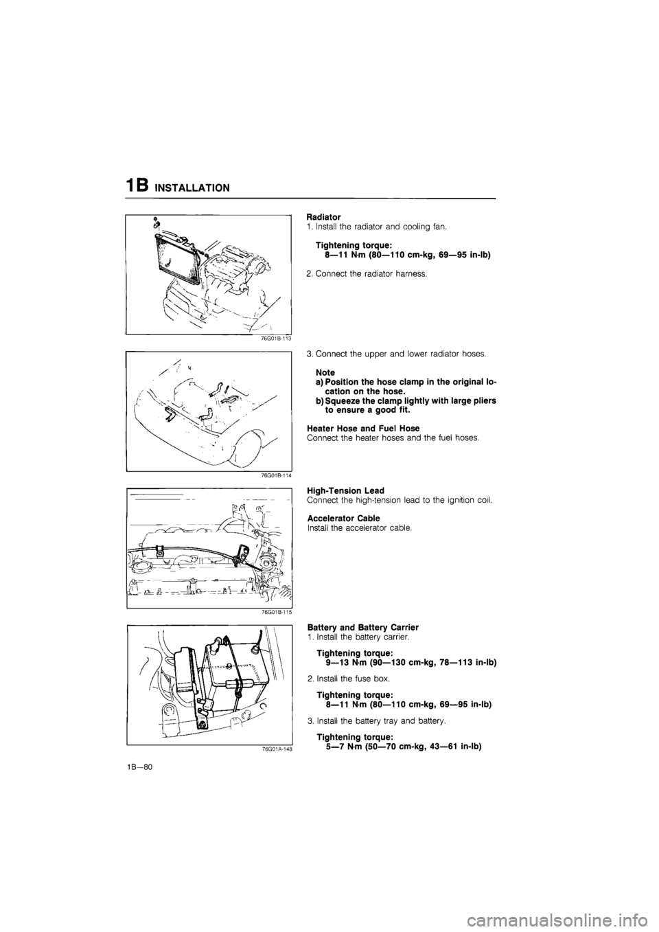
1B INSTALLATION
76G01B-113
76G01B-114
76G01B-115
Radiator
1. Install the radiator and cooling fan.
Tightening torque:
8—11 N-m (80—110 cm-kg, 69—95 in-lb)
2. Connect the radiator harness.
3. Connect the upper and lower radiator hoses.
Note
a) Position the hose clamp in the original lo-
cation on the hose.
b) Squeeze the clamp lightly with large pliers
to ensure a good fit.
Heater Hose and Fuel Hose
Connect the heater hoses and the fuel hoses.
High-Tension Lead
Connect the high-tension lead to the ignition coil.
Accelerator Cable
Install the accelerator cable.
76G01A-148
Battery and Battery Carrier
1. Install the battery carrier.
Tightening torque:
9—13 N-m (90—130 cm-kg, 78—113 in-lb)
2. Install the fuse box.
Tightening torque:
8—11
N
m (80—110 cm-kg, 69—95 in-lb)
3. Install the battery tray and battery.
Tightening torque:
5_7
N m
(50—70 cm-kg, 43—61 in-lb)
1B—80
Page 243 of 1865

REMOVAL 1C
REMOVAL
1. Disconnect the negative battery cable.
2. Drain the engine oil and coolant.
3. Remove in the sequence shown in the figure referring to the removal note for specially marked parts.
76G01C-071
1. Battery and battery carrier
2. Accelerator cable
3. Air cleaner assembly
4. Radiator harness
5. Radiator hose
6. Radiator and cooling fan
7. Brake vacuum hose
8. Intercooler pipe and hose*
9. Fuel hose
10. Drive belt cover
Note
11. P/S pump
12. No.4 engine mount
13. Clutch release cylinder
14. Speedometer cable
15. Transaxle harness
16. A/C compressor
17. Engine harness
18. Heater hose
19. Front wheel
20. Engine side cover
21. Tie-rod end
22. Stabilizer control rod
23. Lower arm bushing
24. Driveshaft
25. Change rod
26. Extension bar
27. Exhaust pipe and stay
28. Engine mount
29. Engine and transaxle
30. Transaxle
marked parts are equipped only for RF-CX.
1C-31
Page 307 of 1865

INSTALLATION 1C
Heater Hose
Connect the heater hoses.
Note
Position the hose clamp in the original loca-
tion on the hose and squeeze the clamp lightly
with large pliers to ensure a good fit.
86U01X-221
Connector Location
Install each harness as shown in the figure.
1. Alternator
2. Boost air temperature sensor (RF-CX)
3. Heat gauge unit
4. Water thermo switch
5. Pick up coil
6. Glow cord
7. Front harness connector and ground
76G01C-222
8. Fuel cut valve
9. Oil pressure switch
10. Starter
11. Water temperature switch
12. Transaxle harness
13. Grounds
1C—95