fuel filter MAZDA 626 1987 Workshop Manual
[x] Cancel search | Manufacturer: MAZDA, Model Year: 1987, Model line: 626, Model: MAZDA 626 1987Pages: 1865, PDF Size: 94.35 MB
Page 15 of 1865
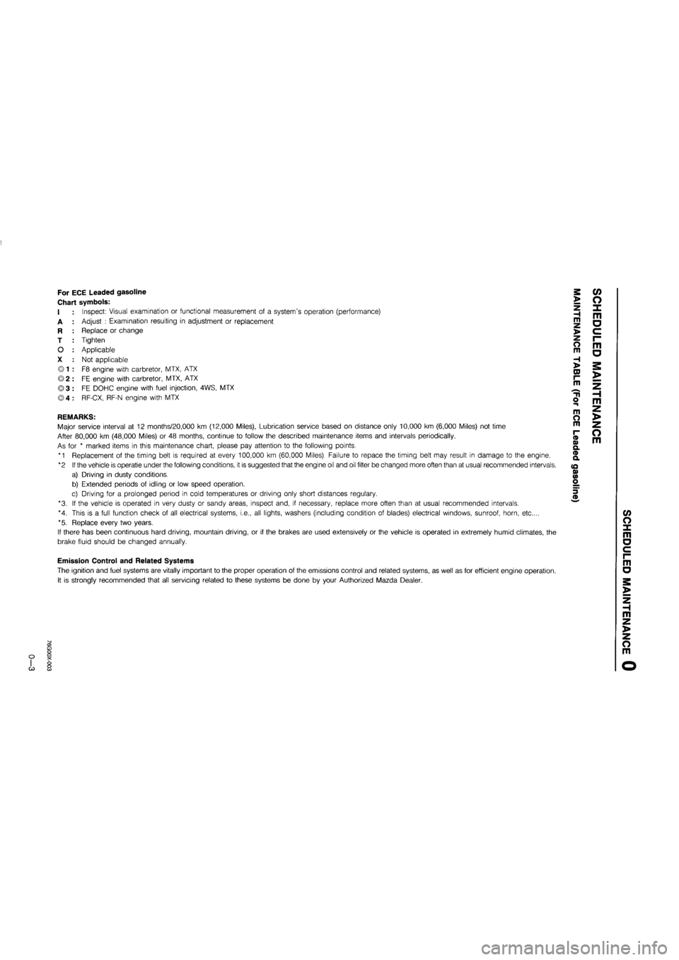
For ECE Leaded gasoline
Chart symbols:
I
A
R
T
O
X
Inspect: Visual examination or functional measurement of a system's operation (performance)
Adjust : Examination resulting in adjustment or replacement
Replace or change
Tighten
Applicable
Not applicable
F8 engine with carbretor, MTX, ATX
FE engine with carbretor, MTX, ATX
FE DOHC engine with fuel injection, 4WS, MTX
RF-CX, RF-N engine with MTX
REMARKS:
Major service interval at 12 months/20,000 km (12,000 Miles), Lubrication service based on distance only 10,000 km (6,000 Miles) not time
After 80,000 km (48,000 Miles) or 48 months, continue to follow the described maintenance items and intervals periodically.
As for * marked items in this maintenance chart, please pay attention to the following points.
*1 Replacement of the timing belt is required at every 100,000 km (60,000 Miles). Failure to repace the timing belt may result in damage to the engine.
*2 If the vehicle is operatie under the following conditions, it is suggested that the engine oil and oil filter be changed more often than at usual recommended intervals.
a) Driving in dusty conditions.
b) Extended periods of idling or low speed operation.
c) Driving for a prolonged period in cold temperatures or driving only short distances regulary.
*3. If the vehicle is operated in very dusty or sandy areas, inspect and, if necessary, replace more often than at usual recommended intervals.
*4. This is a full function check of all electrical systems, i.e., all lights, washers (including condition of blades) electrical windows, sunroof, horn, etc....
*5. Replace every two years.
If there has been continuous hard driving, mountain driving, or if the brakes are used extensively or the vehicle is operated in extremely humid climates, the
brake fluid should be changed annually.
>
Z H m >
o m
H >
CD r-m
o m
m O m
(D o> Q. ® a
(Q 0) <0 o
m a
o m
c/> o x m a
Emission Control and Related Systems
The ignition and fuel systems are vitally important to the proper operation of the emissions control and related systems, as well as for efficient engine operation.
It is strongly recommended that all servicing related to these systems be done by your Authorized Mazda Dealer.
m a
m z >
z o m
G)
Page 17 of 1865

U1
Interval
Procedure & item
Number of Months or km, whichever corns first
©1 ©2 ©3 ©4 Service data and inspection point Page
Interval
Procedure & item
Months — 6 12 18 24 30 36 42 48 ©1 ©2 ©3 ©4 Service data and inspection point Page
Interval
Procedure & item
x 1000 Km
1 10 20 30 40 50 60 70 80 ©1 ©2 ©3 ©4 Service data and inspection point Page
Interval
Procedure & item
Miles x
1000 0.6 6 12 18 24 30 36 42 48
©1 ©2 ©3 ©4 Service data and inspection point Page
Battery electrolyte level and specific gravity A A A A O o O O • Electroyte level • Specific gravity 5-8
Drive belts A A A A A O 0 o O • Cracks or damage • Tension
1
A—7
1B—6
1C-7
Engine timing belts Replace every 100,000 Km o o o o — 1A—14 1B—11 1C—11
Engine valve clearance A A A A A o X X o
• Valve clearance: F8 (Hot engine) IN: 0.30 mm (0.012 in) EX: 0.30 mm (0.012 in) FE-12-valve, FE (DOHC) IN: 0; Maintenance free EX: 0; Maintenance free RF-CX, RF-N (Cold engine) IN: 0.25 mm (0.010 in) EX: 0.35 mm (0.014 in)
1A-10
1C—85
Intake and exhaust manifold nuts and
bolts T T T o o X X
• Retighten the intake and exhaust manifold nuts
N-m (m-kg, ft-lb)
1
A—86 1B—68 1C—89
Intake and exhaust manifold nuts and
bolts T T T o o X X IN EX
1
A—86 1B—68 1C—89
Intake and exhaust manifold nuts and
bolts T T T o o X X F8, FE 19-30 (1.9-3.1,
14-22)
22-28 (22—2.9, 16-21)
1
A—86 1B—68 1C—89
Intake and exhaust manifold nuts and
bolts T T T o o X X
RF-CX RF-N 16-23 (1.6-2,3,
12-17)
22-26 (2.2-2.7,
16-20)
1
A—86 1B—68 1C—89
Engine oil *2 R R R R R R R R R o o 0 o
• Oil pan capacity F8, FE: 3.6 liters (3.8 US qt, 3.2 Imp qt) RF-CX, RF-N:
5.0 liters (5.3 US qt, 4.4 Imp qt)
2A—6
2B-6
Oil filter *2 R R R R R R R R o o o o
• Oil filter capacity F8, FE 12-valve
0.3 liters (0.32 US qt, 0.26 Imp qt) FE (DOHC)
0.2 liters (0.21 US qt, 0.18 Imp qt) RF-CX, RF-N
0.4 liters (0.42 US qt, 0.35 Imp qt)
2A—6
2B-6
Fuel filter (R) for carbretor model (R) R (R) R o 0 o o — 4A—37
Page 21 of 1865
r
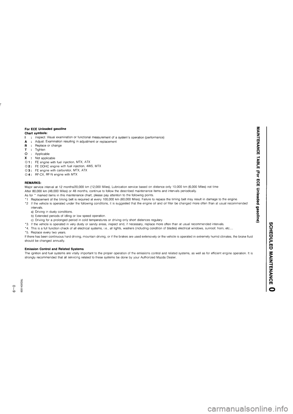
For ECE Unleaded gasoline
Chart symbols:
I
A
R
T
O
X
Inspect: Visual examination or functional measurement of a system's operation (performance)
Adjust: Examination resulting in adjustment or replacement
Replace or change
Tighten
Applicable
Not applicable
FE engine with fuel injection, MTX, ATX
FE DOHC engine with fuel injection, 4WS, MTX
FE engine with carburetor, MTX, ATX
RF-CX, RF-N engine with MTX
REMARKS:
Major service interval at 12 months/20,000 km (12,000 Miles), Lubrication service based on distance only 10,000 km (6,000 Miles) not time
After 80,000 km (48,000 Miles) or 48 months, continue to follow the described maintenance items and intervals periodically.
As for * marked items in this maintenance chart, please pay attention to the following points.
*1 Replacement of the timing belt is required at every 100,000 km (60,000 Miles). Failure to repace the timing belt may result in damage to the engine.
*2 If the vehicle is operated under the following conditions, it is suggested that the engine oil and oil filter be changed more often than at usual recommended
intervals.
a) Driving in dusty conditions.
b) Extended periods of idling or low speed operation.
c) Driving for a prolonged period in cold temperatures or driving only short distances regulary.
*3. If the vehicle is operated in very dusty or sandy areas, inspect and, if necessary, replace more often than at usual recommended intervals.
*4. This is a full function check of all electrical systems, i.e., all lights, washers (including condition of blades) electrical windows, sunroof, horn, etc....
*5. Replace every two years.
If there has been continuous hard driving, mountain driving, or if the brakes are used extensively or the vehicle is operated in extremely humid climates, the brake fluid
should be changed annually.
Emission Control and Related Systems
The ignition and fuel systems are vitally important to the proper operation of the emissions control and related systems, as well as for efficient engine operation. It is
strongly recommended that all servicing related to these systems be done by your Authorized Mazda Dealer.
>
Z H m z >
o m
H >
DJ r~ m
m o m
c 3
(/> O X m o c i-m
o
m z >
z o m
CD
Page 24 of 1865
o
r\3
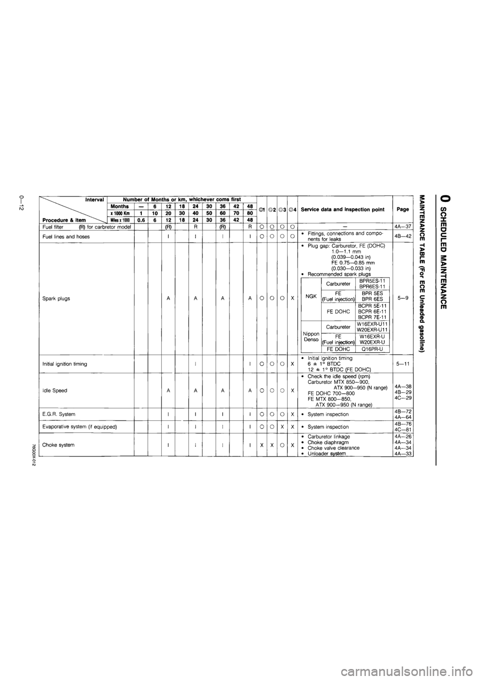
Interval
Procedure & item
Number of Months or km, whichever corns first
Months
x
1000 Km
Miles x 1000
Fuel filter (R) for carbretor model
Fuel lines and hoses
Spark plugs
Initial ignition timing
Idle Speed
E.G.R. System
Evaporative system (if equipped)
O) O
X o
Choke system
0.6
6
10
12
20
12
(R)
18
30
18
24
40
24
30
50
30
36
60
36
(R)
42
70
42
48
80
48
©1
O
O
o
o
o
o
o
o
o
o
o
o
o
o
©3
o
o
o
o
o
o
o
©4
o
o
Service data and inspection point
Fittings, connections and compo-
nents for leaks
Plug gap: Carburetor, FE (DOHC) 1.0—1.1 mm (0.039—0.043 in) FE 0.75—0.85 mm (0.030-0.033 in) Recommended spark plugs
NGK
Carbureter BPR5ES-11 BPR6ES-11
NGK FE
(Fuel injection)
BPR 5ES
BPR 6ES NGK
FE DOHC
BCPR 5E-11 BCPR 6E-11 BCPR 7E-11
Nippon Denso
Carbureter W16EXR-U11 W20EXR-U11 Nippon Denso FE
(Fuel injection)
W16EXR-U
W20EXR-U
Nippon Denso
FE DOHC Q16PR-U
Initial ignition timing
6 ±
1
° BTDC
12 ± 1° BTDC (FE DOHC)
Check the idle speed (rpm) Carburetor MTX 850—900,
ATX 900-950 (N range) FE DOHC 700-800 FE MTX 800—850,
ATX 900-950 (N range)
System inspection
System inspection
Carburetor linkage Choke diaphragm Choke valve clearance Unloader system
Page
4A-37
4B-42
5-9
5-11
4A—38 4B-29 4C—29
4B—72 4A—64
4B—76
4C-81
4A-26 4A—34 4A—34 4A—33
m z >
z o m
H >
00 r-m
H o
m O m
3
CO o X m a c i-m a
m z >
z o m
Page 27 of 1865
For General
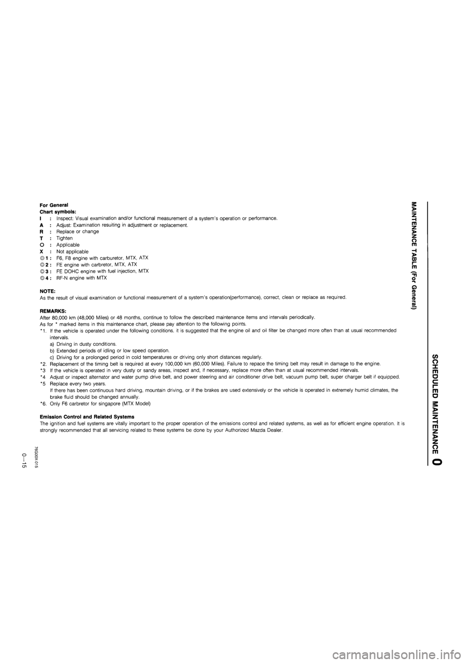
Chart symbols:
I : Inspect: Visual examination and/or functional measurement of a system's operation or performance.
A : Adjust: Examination resuiting in adjustment or replacement.
R : Replace or change
T : Tighten
O : Applicable
X : Not applicable
© 1 : F6, F8 engine with carburetor, MTX, ATX
© 2 : FE engine with carbretor, MTX, ATX
©3 : FE DOHC engine with fuel injection, MTX
® 4 : RF-N engine with MTX
NOTE:
As the result of visual examination or functional measurement of a system's operation(performance), correct, clean or replace as required.
REMARKS:
After 80,000 km (48,000 Miles) or 48 months, continue to follow the described maintenance items and intervals periodically.
As for * marked items in this maintenance chart, please pay attention to the following points.
*1. If the vehicle is operated under the following conditions, it is suggested that the engine oil and oil filter be changed more often than at usual recommended
intervals.
a) Driving in dusty conditions.
b) Extended periods of idling or low speed operation.
c) Driving for a prolonged period in cold temperatures or driving only short distances regularly.
"2. Replacement of the timing belt is required at every 100,000 km (60,000 Miles). Failure to repace the timing belt may result in damage to the engine.
*3 If the vehicle is operated in very dusty or sandy areas, inspect and, if necessary, replace more often than at usual recommended intervals.
*4 Adjust or inspect alternator and water pump drive belt, and power steering and air conditioner drive belt, vacuum pump belt, super charger belt if equipped.
*5 Replace every two years.
If there has been continuous hard driving, mountain driving, or if the brakes are used extensively or the vehicle is operated in extremely humid climates, the
brake fluid should be changed annually.
*6. Only F6 carbretor for Singapore (MTX Model)
Emission Control and Related Systems
The ignition and fuel systems are vitally important to the proper operation of the emissions control and related systems, as well as for efficient engine operation. It i
strongly recommended that all servicing related to these systems be done by your Authorized Mazda Dealer.
o CJ1
Page 30 of 1865
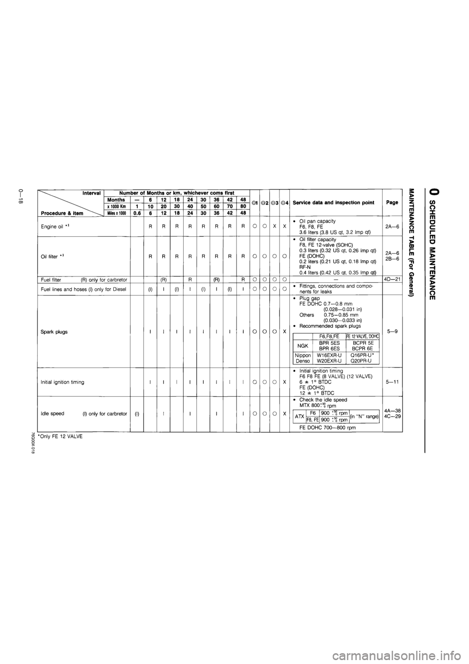
Interval
Procedure & item
Number of Months or km, whichever corns first
Months
x 1000 Km
Miles x 1000
Engine oil
Oil filter
Fuel filter (R) only for carbretor
Fuel lines and hoses (I) only for Diesel
Spark plugs
Initial ignition timing
Idle speed (I) only for carbretor
0.6
(I)
6
10
(0
12
20
12
(R)
18
30
18
(I)
24
40
24
30
50
30
(I)
36
60
36
(R)
42
70
42
(I)
48
80
48
®1
O
o
o
o
o
o
o
©2
O
o
o
o
o
o
o
©3
O
o
o
o
o
o
©4
O
o
o
Service data and inspection point
Oil pan capacity F6, F8, FE 3.6 liters (3.8 US qt, 3.2 Imp qt)
Oil filter capacity F8, FE 12-valve (SOHC)
0.3 liters (0.32 US qt, 0.26 Imp qt)
FE (DOHC) 0.2 liters (0.21 US qt, 0.18 Imp qt) RF-N
0.4 liters (0.42 US qt, 0.35 Imp qt)
Fittings, connections and compo-
nents for leaks
Plug gap FE DOHC 0.7—0.8 mm (0.028-0.031 in) Others 0.75—0.85 mm (0.030—0.033 in) Recommended spark plugs
F6,F8,FE FE
12 VALVE,
DOHC
NGK BPR 5ES BPR 6ES BCPR 5E
BCPR 6E
Nippon
Denso W16EXR-U
W20EXR-U
Q16PR-U* Q20PR-U
Initial ignition timing F6 F8 FE (8 VALVE) (12 VALVE)
6 ±
1
° BTDC FE (DOHC) 12 ± 1° BTDC
Check the idle speed
MTX 80015? rpm
ATX F6 900 rpm (in "N" range) ATX F8, FE 900 t5? rpm (in "N" range)
FE DOHC 700—800 rpm
§ *Only FE 12 VALVE
Page
2A—6
2A-6
2B-6
4D—21
5-9
5-11
4A—38
4C-29
m z >
z o m
H >
CD I-m
T1
o
o
m z >
z o m
Page 156 of 1865
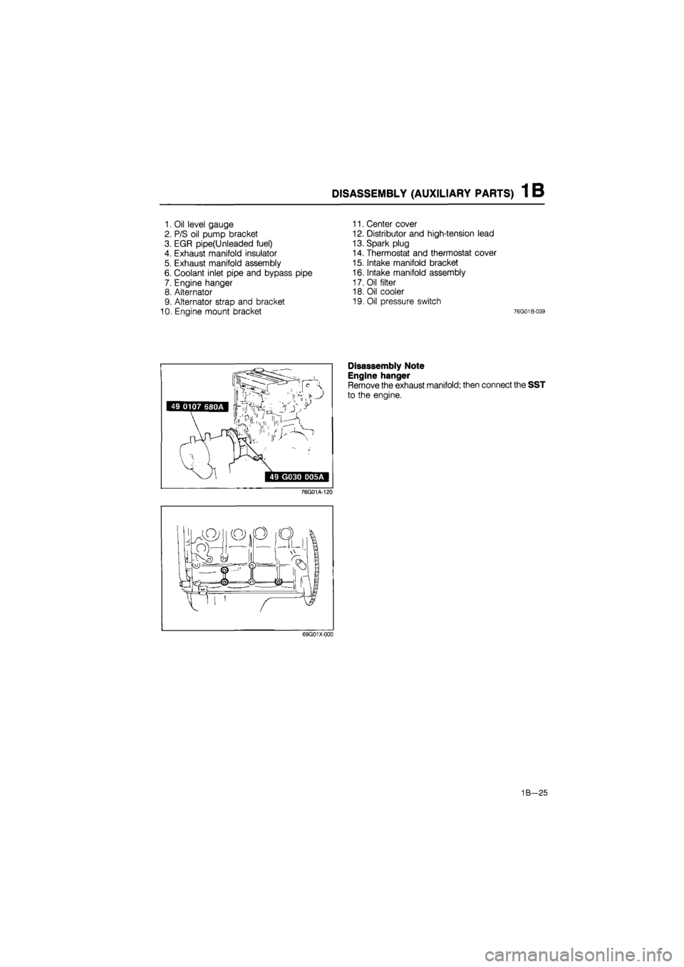
DISASSEMBLY (AUXILIARY PARTS) 1 B
1. Oil level gauge
2. P/S oil pump bracket
3. EGR pipe(Unleaded fuel)
4. Exhaust manifold insulator
5. Exhaust manifold assembly
6. Coolant inlet pipe and bypass pipe
7. Engine hanger
8. Alternator
9. Alternator strap and bracket
10. Engine mount bracket
11. Center cover
12. Distributor and high-tension lead
13. Spark plug
14. Thermostat and thermostat cover
15. Intake manifold bracket
16. Intake manifold assembly
17. Oil filter
18. Oil cooler
19. Oil pressure switch
76G01B-039
49 0107 680A Irf^Ys'^
,v,, I
' ir
>
49 G030 D05A
76G01A-120
Disassembly Note
Engine hanger
Remove the exhaust manifold; then connect the SST
to the engine.
69G01X-000
1B—25
Page 218 of 1865
1C TUNE-UP PROCEDURE
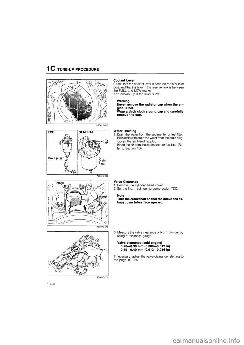
Coolant Level
Check that the coolant level is near the radiator inlet
port, and that the level in the reserve tank is between
the FULL and LOW marks.
Add coolant up if the level is low.
Warning
Never remove the radiator cap when the en-
gine is hot.
Wrap a thick cloth around cap and carefully
remove the cap.
4BG01B-010
Water Draining
1. Drain the water from the sedimenter or fuel filter.
If it is difficult to drain the water from the drain plug,
loosen the air bleeding plug.
2. Bleed the air from the sedimenter or fuel filter. (Re-
fer to Section 4D)
76G01C-005
Valve Clearance
1. Remove the cylinder head cover.
2. Set the No. 1 cylinder to compression TDC.
Note
Turn the crankshaft so that the intake and ex-
haust cam lobes face upward.
4BG01B-016
3. Measure the valve clearance of No. 1 cylinder by
using a thickness gauge.
Valve clearance (cold engine)
0.20—0.30 mm (0.008—0.012 in)
0.30—0.40 mm (0.012—0.016 in)
If necessary, adjust the valve clearance referring to
the page 1C—85.
76G01C-006
1C-6
Page 366 of 1865

4A
FUEL AND EMISSION
CONTROL SYSTEMS
(CARBURETOR)
OUTLINE 4A— 2
SYSTEM DIAGRAM 4A— 2
VACUUM HOSE ROUTING
DIAGRAM 4A— 5
EMISSION COMPONENTS
LOCATION 4A— 8
COMPONENT DESCRIPTIONS 4A—12
SPECIFICATIONS 4A—15
TROUBLESHOOTING GUIDE 4A—17
PARTS INSPECTION 4A—23
AIR CLEANER ELEMENT 4A—23
ACCELERATOR LINKAGE 4A—23
INTAKE MANIFOLD 4A—23
CHOKE CABLE 4A—23
FUEL SYSTEM 4A—24
TROUBLESHOOTING 4A—25
CARBURETOR 4A—26
FUEL PUMP 4A—35
FUEL TANK 4A—36
SEPARATOR 4A—37
TWO-WAY CHECK VALVE 4A—37
THREE-WAY CHECK VALVE 4A—37
FUEL FILTER 4A—37
IDLE SPEED AND IDLE MIXTURE.. 4A—38
ADJUSTMENT 4A—38
AUTO-RETURN CHOKE SYSTEM... 4A—40
TROUBLESHOOTING 4A—40
PTC HEATER SYSTEM 4A—42
TROUBLESHOOTING 4A—42
DECELERATION CONTROL SYSTEM 4A—45
TROUBLESHOOTING 4A—45
BYPASS AIR CONTROL SYSTEM.. 4A—48
DASH POT 4A—50
ANTI-AFTERBURN VALVE 4A—50
MAIN AIR BLEED CONTROL
SYSTEM 4A—51
SLOW FUEL CUT SYSTEM 4A—53
COAST ENRICHMENT SYSTEM .... 4A—54
COASTING LEANER SYSTEM 4A—56
AIR INJECTION SYSTEM 4A—58
INTAKE AIR TEMPERATURE CONTROL
SYSTEM 4A—60
TROUBLESHOOTING 4A—60
PURGE CONTROL SYSTEM 4A—63
VACUUM SWITCH VALVE 4A—63
EXHAUST GAS RECIRCULATION
(EGR) SYSTEM 4A—64
TROUBLESHOOTING 4A—65
POSITIVE CRANKCASE VENTILATION
SYSTEM 4A—67
PCV VALVE 4A—67
IDLE-UP CONTROL SYSTEM 4A—68
TROUBLESHOOTING 4A—70
IDLE-UP SOLENOID VALVE 4A—76
EVAPORATIVE EMISSION CONTROL
SYSTEM 4A—78
TROUBLESHOOTING 4A—79
IGNITION TIMING CONTROL
SYSTEM 4A-80
TROUBLESHOOTING 4A—81
CONTROL SYSTEM 4A-83
RELATIONSHIP CHART 4A—84
ENGINE CONTROL UNIT 4A—86
INHIBITOR SWITCH 4A—93
IDLE SWITCH 4A—93
VACUUM SWITCH 4A—94
WATER THERMO SWITCH 4A—95
EXHAUST SYSTEM 4A—96
76G04A-001
Page 378 of 1865

OUTLINE
4A
Previous
626
Unlead-
ed
fuel
O O O O O O X O O O X
Previous
626
Leaded
fuel
O X X O O X X X O X
New
626
FE
8
Valve
Unlead-
ed
fuel
o O O O O O X X O O O
New
626
Sin-
gapore
o O X O O m O
O
(FE
&
F8)
O
O
(FE
&
F8)
O O
New
626
Middle
East
o X X O O X X X X X O
New
626
General
X
O
(FE
& F8)
X O O X
O
(FE
&
F8)
O
(FE
&
F8)
O
(FE
&
F8)
X o
New
626
ECE
&
Hong
Kong
o O X O O * O O O O O o
Remark
• Adjustment
speed:
2,200
±
100
rpm
(in
neutral).
• MTX • Operation:
Coolant
tempera-
ture
more
than
50°C
(122°F).
Mechanical
type
Installed
on
carburetor.
Improvement
of
product
quality.
Function
Allows
throttle
to
gradually
close
during
deceleration.
Reduces
CO
and
HC
emission.
Detects
electrical
signal
from
in-
put
devices
and
controls
output
devices. Supplies
exhaust
gas
to
intake
manifold
to
reduce
NOx
Filters
fuel
Provides
fuel
to
carburetor.
Detects
when
throttle
valve
fully
closed. Opens
fuel
passage
to
secon-
dary
stage
of
carburetor.
Controls
shutter
valve
by
intake
air
temperature. Prevents
carburetor
icing.
Supplies
fresh
air
to
exhaust
manifold
to
reduce
CO
and
HC
emissions. Prevents
fuel
from
flowing
into
two-way
or
three-way
check
valve
Component
Dashpot Engine
Contorol
Unit
EGR
Control
Valve
Fuel
Filter
Fuel
Pump
Idle
Switch
Idle-up
Solenoid
Valve
Intake
Air
Temperature
Control
Valve
PTC
Heater
Reed
Valve
Separator
•a a> a -a .2-S
3
9-a a) 5 u- O UJ
z
Ox
111 IL •a c
V (-
U.ps •o
-
X
_ X
I-
o-t-
s ®
s
*
o *
oo
x to
U. UJ
u.
T- oi CO
4 A—13