tire size MAZDA 626 1987 Workshop Manual
[x] Cancel search | Manufacturer: MAZDA, Model Year: 1987, Model line: 626, Model: MAZDA 626 1987Pages: 1865, PDF Size: 94.35 MB
Page 37 of 1865

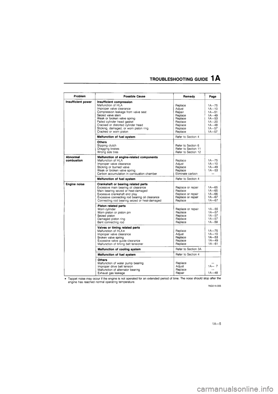
TROUBLESHOOTING GUIDE 1 A
Problem Possible Cause Remedy Page
Insufficient power Insufficient compression Malfunction of HLA Improper valve clearance Compression leakage from valve seat Seized valve stem Weak or broken valve spring Failed cylinder head gasket Cracked or distorted cylinder head Sticking, damaged, or worn piston ring Cracked or worn piston
Replace
Adjust
Repair
Replace Replace Replace Replace Replace Replace
1A—75 1A—10
1
A—51 1A—49 1A—53
1
A—20 1A—48 1A—57
1
A—57
Malfunction of fuel system Refer to Section 4
Others Slipping clutch Dragging brakes Wrong size tires
Refer to Section 6 Refer to Section 11 Refer to Section 12
Abnormal
combustion
Malfunction of engine-related components Malfunction of HLA
Improper valve clearance Sticking or burned valve
Weak or broken valve spring Carbon accumulation in combustion chamber
Replace Adjust Replace Replace
Eliminate carbon
1
A—75 1A—10 1A—49 1A—53
Malfunction of fuel system Refer to Section 4
Engine noise Crankshaft or bearing related parts
Excessive main bearing oil clearance Main bearing seized or heat-damaged Excessive crankshaft end play Excessive connecting rod bearing oil clearance Connecting rod bearing seized or heat-damaged
Replace or repair Replace
Replace or repair Replace or repair Replace
1A—65
1
A—65 1A—66 1A—67
1
A—67
Piston related parts Worn cylinder Worn piston or piston pin Seized piston Damaged piston ring Bent connecting rod
Replace or repair
Replace
Replace Replace Replace
1A—55
1
A—57
1
A—57
1
A—57 1A—59
Valves or timing related parts Malfunction of HLA* Improper valve clearance Broken valve spring Excessive valve guide clearance Malfunction of timing belt tensioner
Replace Adjust
Replace Replace Replace
1A—75 1A—10 1A—53 1A—49 1A—61
Malfunction of cooling system Refer to Section 3A
Malfunction of fuel system Refer to Section 4
Others Malfunction of water pump bearing Improper drive belt tension Malfunction of alternator bearing Exhaust gas leakage
Replace Adjust Replace Repair
1 A— 7
1
A—48
* Tappet noise may occur if the engine is not operated for an extended period of time. The noise should stop after the
engine has reached normal operating temperature.
76G01A-005
1A—5
Page 89 of 1865

INSPECTION AND REPAIR 1A
76G01A-068
Piston
1. Inspect the outer circumferences of all pistons for
seizure or scoring. Replace if necessary.
2. Measure the outer diameter of each piston at a right
angle (90°) to the piston pin, 18 mm (0.709 in)
below the oil ring land lower edge.
Piston diameter mm (in)
Size Diameter
LU
OO LL LL Standard 85.944-85.964 (3.3836-3.3844)
LU
OO LL LL 0.25 (0.010) oversize 86.194-86.214 (3.3935-3.3942)
LU
OO LL LL
0.50 (0.020) oversize 86 444-86.464 (3.4033-3.4041)
F6
Standard 80 944-80.964 (3.1868-3.1876)
F6
0.25 (0.010) oversize 81.194-81.214 (3.1966-3.1974)
F6 0.50 (0.020) oversize 81.444-81.464 (3.2065-3.2072) F6
0.75 (0.030) oversize 81.694-81.714 (3.2163-3.2171)
F6
1.00 (0.039) oversize 81.944-81.964 (3.2261-3,2269)
3. Check the piston to cylinder clearance.
ClGdrsncG1
0.036—0.075 mm (0.0014—0.0030 in)
Maximum: 0.15 mm (0.0059 in)
4. If the clearance exceeds the maximum, replace the
piston or rebore the cylinders to fit oversize pistons.
Caution
If the piston is replaced, replace the piston
rings also.
76G01A-130
Piston and Piston Ring
1. Measure the piston ring to ring land clearance
around the entire circumference using a new pis-
ton ring.
Clearance (Top and Second):
0.03—0.07 mm (0.001—0.003 in)
Maximum: 0.15 mm (0.006 in)
2. If the clearance exceeds the maximum, replace the
piston.
69G01A-125
1A—57
Page 135 of 1865

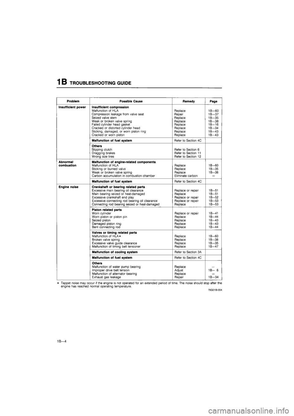
TROUBLESHOOTING GUIDE 1 B
Problem Possible Cause Remedy Page
Insufficient power Insufficient compression Malfunction of HLA Compression leakage from valve seat Seized valve stem Weak or broken valve spring Failed cylinder head gasket Cracked or distorted cylinder head Sticking, damaged, or worn piston ring Cracked or worn piston
Replace Repair
Replace
Replace Replace Replace Replace Replace
1B—60 1B—37 1B—35 1B—38 1B-16 1B—34 1B—43 1B—43
Malfunction of fuel system Refer to Section 4C
Others Slipping clutch Dragging brakes Wrong size tires
Refer to Section 6 Refer to Section 11 Refer to Section 12
Abnormal combustion Malfunction of engine-related components Malfunction of HLA Sticking or burned valve
Weak or broken valve spring Carbon accumulation in combustion chamber
Replace Replace Replace
Eliminate carbon
1B-60
1B-35
1B—38
Malfunction of fuel system Refer to Section 4C
Engine noise Crankshaft or bearing related parts
Excessive main bearing oil clearance Main bearing seized or heat-damaged Excessive crankshaft end play Excessive connecting rod bearing oil clearance Connecting rod bearing seized or heat-damaged
Replace or repair Replace
Replace or repair Replace or repair Replace
1B-51 1B—51 1B—52 1B—53 1B—53
Piston related parts
Worn cylinder Worn piston or piston pin Seized piston Damaged piston ring Bent connecting rod
Replace or repair
Replace
Replace Replace Replace
1B—41 1B-44 1B—43 1B—43 1B-44
Valves or timing related parts Malfunction of HLA* Broken valve spring Excessive valve guide clearance Malfunction of timing belt tensioner
Replace Replace Replace Replace
1B-60 1B—38 1B—35 1B—47
Malfunction of cooling system Refer to Section 3A
Malfunction of fuel system Refer to Section 4C
Others Malfunction of water pump bearing Improper drive belt tension Malfunction of alternator bearing Exhaust gas leakage
Replace Adjust Replace Repair
1B— 6
1B—34
* Tappet noise may occur if the engine is not operated for an extended period of time. The noise should stop after the engine has reached normal operating temperature. 76G01B-004
1B—4
Page 174 of 1865

INSPECTION AND REPAIR 1 B
Oil ring
groove
18mm IJUv. (0.709 in)*"! ^
79G01C-073
r Clearance
76G01A-130
69G01A-125
HV JT
101
^^Piston ring
vAv n^-n
iXXi ^^Piston ring ^^Piston ring
Piston
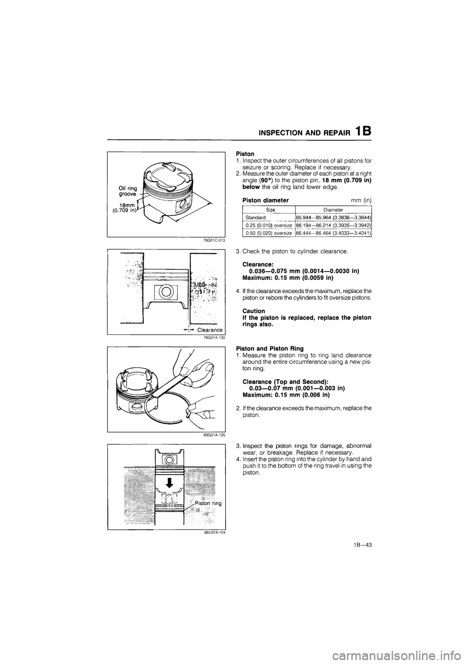
1. Inspect the outer circumferences of all pistons for
seizure or scoring. Replace if necessary.
2. Measure the outer diameter of each piston at a right
angle (90°) to the piston pin, 18 mm (0.709 in)
below the oil ring land lower edge.
Piston diameter mm (in)
Size Diameter
Standard 85.944—85.964 (3.3836—3.3844)
0.25 (0.010) oversize 86.194-86.214 (3.3935-3.3942)
0.50 (0.020) oversize 86.444-86.464 (3.4033-3.4041)
3. Check the piston to cylinder clearance.
Clearance:
0.036—0.075 mm (0.0014—0.0030 in)
Maximum: 0.15 mm (0.0059 in)
4. If the clearance exceeds the maximum, replace the
piston or rebore the cylinders to fit oversize pistons.
Caution
If the piston is replaced, replace the piston
rings also.
Piston and Piston Ring
1. Measure the piston ring to ring land clearance
around the entire circumference using a new pis-
ton ring.
Clearance (Top and Second):
0.03—0.07 mm (0.001—0.003 in)
Maximum: 0.15 mm (0.006 in)
2. If the clearance exceeds the maximum, replace the
piston.
Inspect the piston rings for damage, abnormal
wear, or breakage. Replace if necessary.
Insert the piston ring into the cylinder by hand and
push it to the bottom of the ring travel in using the
piston.
86U01X-101
1B—43
Page 216 of 1865

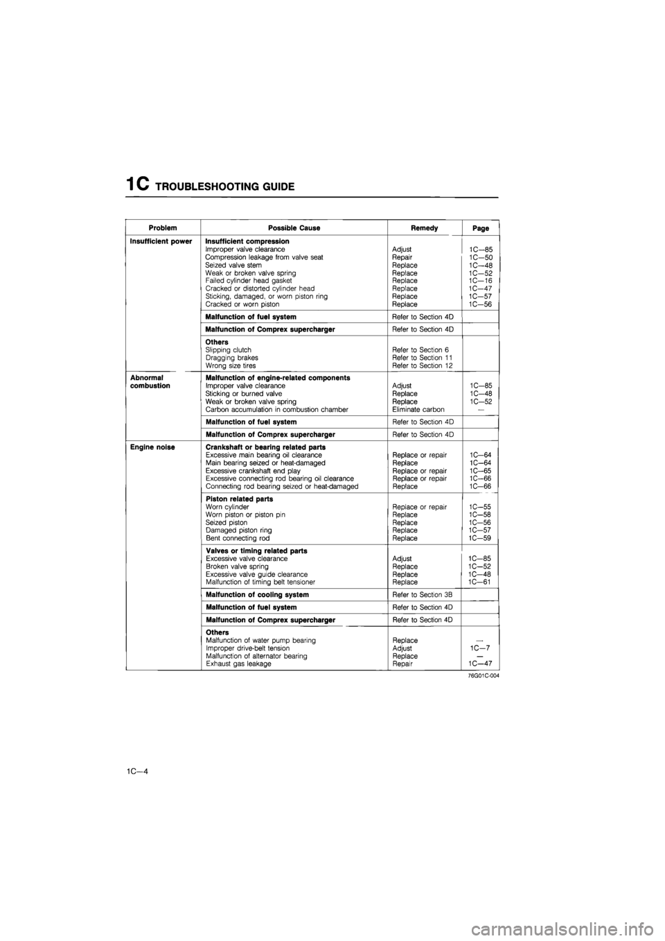
1 C TROUBLESHOOTING GUIDE
Problem Possible Cause Remedy Page
Insufficient power Insufficient compression Improper valve clearance Compression leakage from valve seat Seized valve stem Weak or broken valve spring Failed cylinder head gasket Cracked or distorted cylinder head Sticking, damaged, or worn piston ring Cracked or worn piston
Adjust
Repair
Replace Replace Replace Replace Replace Replace
1C-85 1C-50 1C-48 1C-52 1C—16 1C-47 1C-57 1C-56
Malfunction of fuel system Refer to Section 4D
Malfunction of Comprex supercharger Refer to Section 4D
Others Slipping clutch Dragging brakes Wrong size tires
Refer to Section 6 Refer to Section 11 Refer to Section 12
Abnormal
combustion
Malfunction of engine-related components
Improper valve clearance
Sticking or burned valve
Weak or broken valve spring
Carbon accumulation in combustion chamber
Adjust
Replace
Replace Eliminate carbon
1C-85
1C-48
1C-52
Malfunction of fuel system Refer to Section 4D
Malfunction of Comprex supercharger Refer to Section 4D
Engine noise Crankshaft or bearing related parts Excessive main bearing oil clearance Main bearing seized or heat-damaged Excessive crankshaft end play Excessive connecting rod bearing oil clearance Connecting rod bearing seized or heat-damaged
Replace or repair Replace
Replace or repair Replace or repair Replace
1C-64 1C-64 1C-65 1C-66 1C-66
Piston related parts Worn cylinder Worn piston or piston pin Seized piston Damaged piston ring Bent connecting rod
Replace or repair Replace
Replace Replace Replace
1C-55 1C-58 1C-56 1C-57 1C-59
Valves or timing related parts Excessive valve clearance Broken valve spring Excessive valve guide clearance Malfunction of timing belt tensioner
Adjust Replace Replace Replace
1C-85 1C-52 1C-48 1C-61
Malfunction of cooling system Refer to Section 3B
Malfunction of fuel system Refer to Section 4D
Malfunction of Comprex supercharger Refer to Section 4D
Others Malfunction of water pump bearing Improper drive-belt tension Malfunction of alternator bearing Exhaust gas leakage
Replace Adjust Replace Repair
1C-7
1C—47
76G01C-004
1C—4
Page 269 of 1865

INSPECTION AND REPAIR 1C
-Clearance
3. Check the piston to cylinder clearance.
Clearance-
0.032—0.050 mm (0.0013—0.0020 in)
Maximum: 0.15 mm (0.0059 in)
4. If the clearance exceeds the maximum, replace the
piston or rebore the cylinders to fit oversize pistons.
Note
If the piston is replaced, replace the piston
rings also.
76G01C-134
69G01A-125
Piston and Piston Ring
1. Measure the piston ring to ring land clearance
around the entire circumference using a new pis-
ton ring.
Clearance (Top)
RF-CX: 0.18—0.22 mm (0.0071—0.0087 in)
RF-N : 0.05—0.09 mm (0.0020—0.0035 in)
Clearance (Second):
0.04—0.08 mm (0.0016—0.0031 in)
Maximum: 0.2 mm (0.008 in)
2.
If
the clearance exceeds the maximum, replace the
piston.
3. Inspect the piston rings for damage, abnormal
wear, or breakage. Replace if necessary.
4. Insert the piston ring into the cylinder by hand and
push it to the bottom of the ring travel in using the
piston.
86U01X-104
5. Measure each piston ring end gap with a feeler
gauge. Replace if necessary.
End gap (Top and second)
RF-CX: 0.20—0.35 mm (0.008—0.014 in)
RF-N : 0.20—0.40 mm (0.008—0.016 in)
End gap (Oil rail):
0.20—0.40 mm (0.008—0.016 in)
Maximum: 1.0 mm (0.039 in)
76G01C-144
1C-57
Page 846 of 1865

7A ASSEMBLY
11. Install the SST.
76G07A-039
76G07A-040
76G07A-041
Thickness (Differential)
mm
(in)
0.10 (0.004) 0.70 (0.026)
0.15 (0.006) 0.75 (0.028)
0.20 (0.008) 0.80 (0.030)
0.25 (0.010) 0.85 (0.032)
0.30 (0.012) 0.90 (0.034)
0.35 (0.014) 0.95 (0.036)
0.40 (0.016) 1.00 (0.038)
0.45 (0.018) 1.05 (0.040)
0.50 (0.020) 1.10 (0.042)
0.60 (0.022) 1.15 (0.044)
0.65 (0.024) 1.20 (0.046)
12. Adjust the selector with the SST until the specified
preload is obtained.
Preload:
0.5 N-m (5 cm-kg, 4.3 in-lb)
13. Use a feeler gauge to measure the gap in the selec-
tor for the differential.
Note
Measure the gap around the entire circumfer-
ence of the selector
76G07A-042
14. Add 0.15 mm (0.0059 in) to the measured clear-
ance and select the combination of shims whose
thickness added is nearest higher than that valve.
See the table for available shim sizes.
Example: 0.32 mm (0.013 in)
0.32 mm (0.013 in) + 0.15 mm (0.006 in) =
0.47 mm (0.019 in).
So the nearest shim (on the thick side) to 0.47
mm (0.019 in) is 0.50 mm (0.020 in).
Note
Use a maximum of two shims.
15. Remove the SST and transaxle case.
16. Remove the primary shaft assembly and the
differential.
17. Remove the bearing outer races.
7A—40
Page 900 of 1865

7B TROUBLESHOOTING (G4A-EL)
STEP 7 (ROAD TEST)
This step is performed to inspect for problems at the various ranges. If these tests show any problems,
adjust or replace by referring to the electronic system component or mechanical sections.
Caution
Perform the test at normal ATF operating temperature (50—80°C, 122—176°F).
D Range Test
Shift point, shift pattern, and shift shock
1. Shift the selector lever to D range and select the Power mode.
2. Accelerate the vehicle with half and full throttle valve opening.
Note
Throttle sensor voltage of the EC-AT Tester represents the throttle valve opening.
3. Check that 1-2, 2-3 and 3-OD up-shifts and downshifts and lock-up are obtained. The shift points
must be as shown in the D range (Power) shift diagram.
Note
a) Drum speed (rpm) of the EC-AT Tester represents the shift point.
b) Vehicle speed of the EC-AT Tester and speedometer and vehicle speed on a chassis
roller may not meet the specified shift pattern because of tire size. Therefore, check
the shift points with the Drum speed.
c) There is no lock-up when the coolant temperature is below 72°C (162°F).
d) There is no overdrive when the cruise control is operating and there is a 3 km/h (1.9
mph) difference between the pre-set cruise speed and vehicle speed, or set or resume
switch is ON.
e) There is no lock-up when the brake pedal is depressed.
4. Check the up-shifts for shift shock or slippage in the same manner.
5. While driving in OD, shift the selector lever to S range and check that 4-3 downshift immediately
occurs, then decelerate and check that engine braking effect is felt in only 3rd gear.
7B—34
Page 919 of 1865

TROUBLESHOOTING (G4A-HL) 7B
STEP 5 (ROAD TEST)
This step is performed to inspect for problems at the various ranges.
If
these tests show any problems,
adjust or replace by referring to the mechanical sections.
Perform the test at normal ATF operating temperature (50—80°C, 122—176°F).
D Range Test
Shift point, shift pattern, and shift shock
1. Shift the selector lever to D range and depress the OD OFF switch.
2. Accelerate the vehicle with half (4/8) and full (8/8) throttle valve opening.
3. Check that 1-2, 2-3 and 3-OD up-shifts and downshifts and lock-up are obtained. The shift points
must be as shown in the D range shift diagram.
Note
a) Vehicle speed on a chassis roller may not meet the specified shift diagram because of
tire size.
b) There is no lock-up or OD when the coolant temperature is below 72°C (162°F), and when
the OD OFF switch is depressed.
4. Check the up and down shifts for shift shock or slippage.
5. While driving in 3rd (50—60 km/h, 31—37 mph) shift the selector lever to 2 range and check that
3-2 downshift immediately occurs, then decelerate and check that engine braking effect is felt in
2nd gear.
D range shift diagram
FE engine
Caution
8/8 n
-OD
0 20(12) 40(25) 60(37) 80(50) 100(63) 120(74) 140(87)
Vehicle speed km/h (mph)
76GC7B-057
7B—53
Page 921 of 1865

TROUBLESHOOTING (G4A-HL) 7B
1 Range Test
Shift pattern
1. Shift the selector lever to 1 range.
2. Accelerate the vehicle with half (4/8) and full (8/8) throttle valve opening.
3. Check that the 1-2 up- and down-shifts are obtained and that no 3rd gear, no OD, and no lock-up
are obtained. The shift points must be as shown in the 1 range shift diagram.
Note
Vehicle speed on a chassis roller may not meet the specified shift diagram because of tire
size.
4. Check the up and down-shifts for shift shock or slippage.
5. Drive in 1st gear then decelerate and check that engine braking effect is felt.
1 range shift diagram
FE engine
8/8-1 i
7/8-
6/8-2
2 CT>
I 4/8-a> a. o a> 3/8-
o
2/8-
1/8-
20 40 60 80 (25) (37) (50)
Vehicle speed km/h (mph)
80 100 120 140 (63) (74) (87) (12)
76G07B-059
7B—55