transmission MAZDA 626 1987 Workshop Manual
[x] Cancel search | Manufacturer: MAZDA, Model Year: 1987, Model line: 626, Model: MAZDA 626 1987Pages: 1865, PDF Size: 94.35 MB
Page 11 of 1865
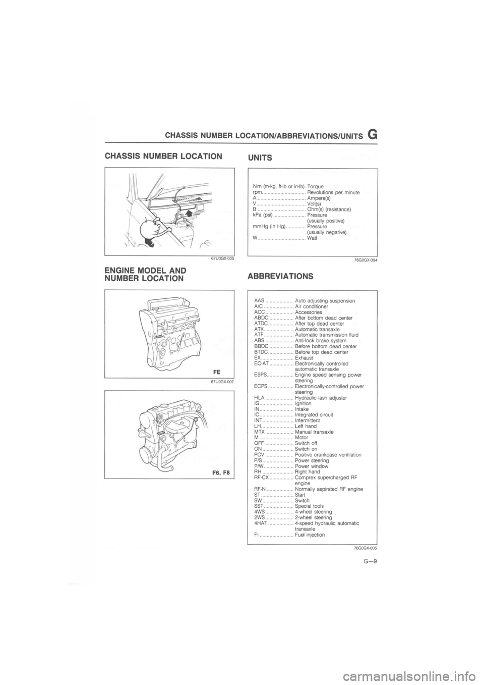
CHASSIS NUMBER LOCATION/ABBREVIATIONS/UNITS G
CHASSIS NUMBER LOCATION UNITS
67U0GX-005
ENGINE MODEL AND
NUMBER LOCATION
Nm (m-kg, ft-lb or in-lb). Torque
rpm Revolutions per minute A Ampere(s) V Volt(s) U Ohm(s) (resistance) kPa (psi) Pressure
(usually positive) mrriHg (in Hg) Pressure
(usually negative) W Watt
76G0GX-004
ABBREVIATIONS
67U0GX-007
AAS Auto adjusting suspension A/C Air conditioner ACC Accessories ABDC After bottom dead center ATDC After top dead center ATX Automatic transaxle ATF Automatic transmission fluid ABS Anti-lock brake system BBDC Before bottom dead center BTDC Before top dead center EX Exhaust EC-AT Electronically controlled automatic transaxle ESPS Engine speed sensing power steering EC PS Electronically-controlled power steering HLA Hydraulic lash adjuster IG Ignition IN Intake IC Integrated circuit INT Intermittent LH Left hand
MTX Manual transaxle M Motor OFF Switch off ON Switch on PCV Positive crankcase ventilation P/S Power steering P/W Power window RH Right hand RF-CX Comprex supercharged RF
engine
RF-N Normally aspirated RF engine ST Start sw Switch SST Special tools 4WS 4-wheel steering
PWS 2-wheel steering
4HAT 4-speed hydraulic automatic
transaxle Fl Fuel injection
76GQGX-005
G—9
Page 129 of 1865
INSTALLATION 1A
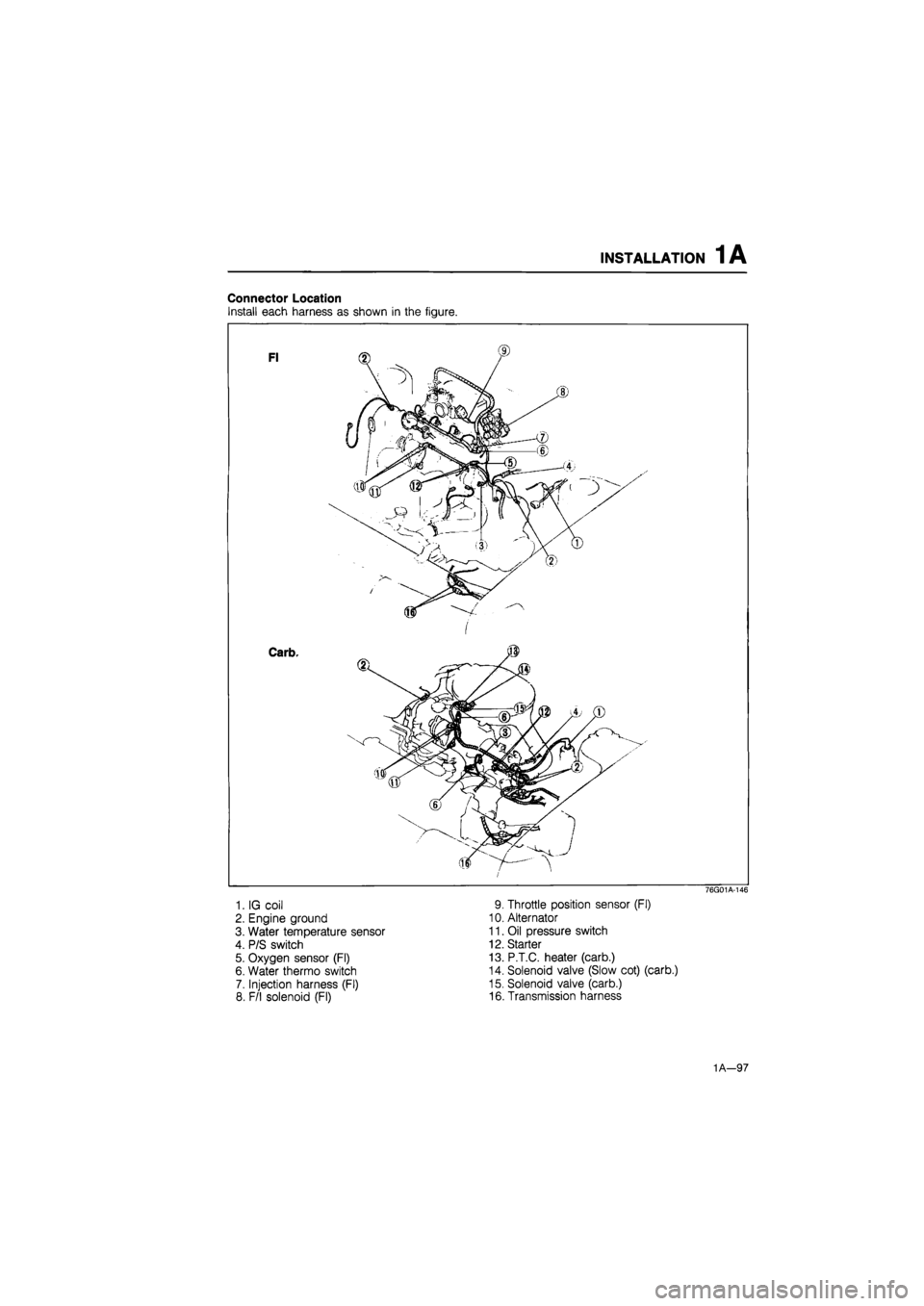
Connector Location
Install each harness as shown in the figure.
1. IG coil
2. Engine ground
3. Water temperature sensor
4. P/S switch
5. Oxygen sensor (Fl)
6. Water thermo switch
7. Injection harness (Fl)
8. F/l solenoid (Fl)
76G01A-146
9. Throttle position sensor (Fl)
10. Alternator
11. Oil pressure switch
12. Starter
13. P.T.C. heater (carb.)
14. Solenoid valve (Slow cot) (carb.)
15. Solenoid valve (carb.)
16. Transmission harness
1A—97
Page 210 of 1865
INSTALLATION 1B
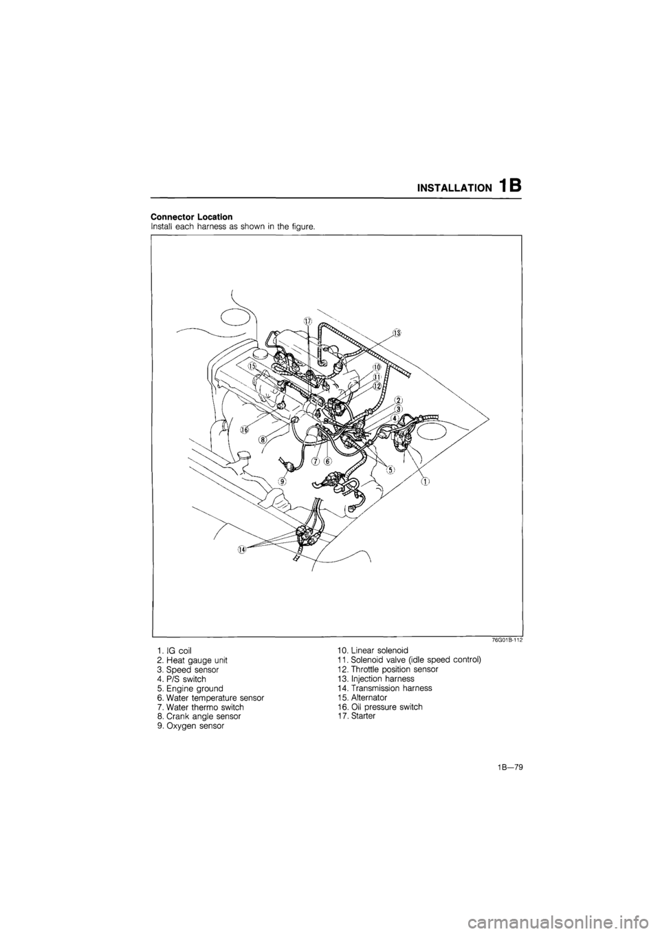
Connector Location
Install each harness as shown in the figure.
76G01B-112
1. IG coil 10. Linear solenoid
2. Heat gauge unit 11. Solenoid valve (idle speed control)
3. Speed sensor 12. Throttle position sensor
4. P/S switch 13. Injection harness
5. Engine ground 14. Transmission harness
6. Water temperature sensor 15. Alternator
7. Water thermo switch 16. Oil pressure switch
8. Crank angle sensor 17. Starter
9. Oxygen sensor
1B-79
Page 398 of 1865

FUEL SYSTEM 4A
76G04A-040
76G04A-041
Clearance
® J t'YCL ® J
V hi /®
'-v
76G04A-042
Fast Idle Opening
FE and F8 (General, ECE, Hong Kong, and Sin-
gapore)
Adjustment of fast idle opening is normally un-
necessary.
But if it is necessary, adjust it as shown.
1. Before adjustment, let the carburetor set at 25WC
(77°F) for at least 1 hour.
2. Check that the center of the cam lever aligns with
the mark (25°) on the fast idle cam.
3. If not as specified, adjust it by turning the adjust
screw.
4. Measure the throttle valve clearance between the
throttle valve and wall with a wire gage.
Specification
Spec. General, ECE, Hong Kong,
and Singapore
Transmission MTX ATX
Clearance mm (in) 0.48—0.64
(0.019-0.025)
0.56—0.72 (0.022-0.028)
5. If not as specified, adjust it by turning the fast idle
adjust screw.
Unloader System
Only FE and F8 (General, ECE, Hong Kong, and
Singapore)
1. Open the primary throttle valve fully.
2. Measure the choke valve clearance.
Clearance-
1.68—2.14 mm (0.066—0.084 in)
3. If not as specified, adjust it by bending tab A.
Slow Fuel Cut Solenoid Valve
1. Start the engine, and run it at idle.
2. Disconnect the connector of the carburetor.
3. Check that the engine stops.
4. If the engine does not stop, replace the slow fuel
cut solenoid valve.
76G04A-043
4A-33
Page 442 of 1865

IDLE-UP CONTROL SYSTEM 4A
Troubleshooting
Note
Make the system inspection first. If no problem is found, continue with the next inspec-
tion of the Troubleshooting. (Refer to page 4A—70.)
\\ Possible cause
\ Page
£ O
S in c o
£ O **
in
0) ** (0 o
o **
s <0
o ** c o o •o d>
£ O **
S (0 o E a>
X 1-<,
£ O
S w £ O
a> > a >
u o c 0) o
c 3
O ** C o
c o s o a> a (0 c
c a E o o
® TJ w <0 4> DC
0) a » c cs IL
a> (0
o
£ C
i « a <
a. 3 a>
Engine
i
terminal
E a>
s. CO
Symptom
Section
15 Section 15 4A—95 4A—93 Section
15 4A—77 4A—86— 4A—91 4A—77
Checking order 3 4 5 6 7 8 2 9 1
76G04A-152
'Engine control unit terminal Check the following terminal voltages
Transmission Terminal
MTX A, C, D, H, Q, R
ATX I, 2B, 2C, 2D, 2E, 2H, 2M
System Inspection
1. Warm up the engine and run it at idle.
2. Connect a jumper wire to the carburetor connec-
tor terminal wire (YW) and ground.
3. Connect a tachometer to the engine.
4. Turn all accessories off.
5. Verify that the engine speed is within specification.
Engine speed: 900—950 rpm (MTX)
Engine speed: 1,000—1,050 rpm
(ATX; in N range)
6. Disconnect the tachometer.
76G04A-153
Idle-up Solenoid Valve
1. Turn all accessories OFF and turn the ignition
switch ON.
2. Disconnect the idle-up solenoid valve connector.
3. Ground the carburetor connector terminal wire
(YW) using with a jumper wire.
4. Check the rod is drawn into the valve.
5. Replace if necessary.
U
76G04A-154
4A-77
Page 553 of 1865

CONTROL SYSTEM 4B
Replacement
1. Disconnect the negative battery cable.
2. Remove the front console covers (right and left).
3. Disconnect the connectors from the control unit.
4. Replace the control unit.
NEUTRAL SWITCH
Inspection
1. Disconnect the neutral switch connector.
2. Connect an ohmmeter to the switch.
3. Check continuity of the switch.
Transmission Continuity
In neutral No
In other ranges Yes
4. After checking, connect the switch connector.
Note
Refer to section 7A for replacement of the
neutral switch.
CLUTCH SWITCH
Inspection
1. Disconnect the clutch switch connector.
2. Connect an ohmmeter to the switch.
3. Check continuity of the switch.
Pedal Continuity
Depressed No
Released Yes
4. After checking, connect the switch connector.
Note
Refer to section 6 for replacement of the
clutch switch.
BRAKE LIGHT SWITCH
Inspection
1. Disconnect the brake light switch connector.
2. Connect an ohmmeter to the switch.
3. Check the continuity of the switch.
Pedal Continuity
Depressed Yes
Released No
4. After checking, connect the switch connector.
Note
Refer to section 11 for replacement of the
brake switch.
4B-91
Page 658 of 1865
CONTROL SYSTEM 4C
Resistance
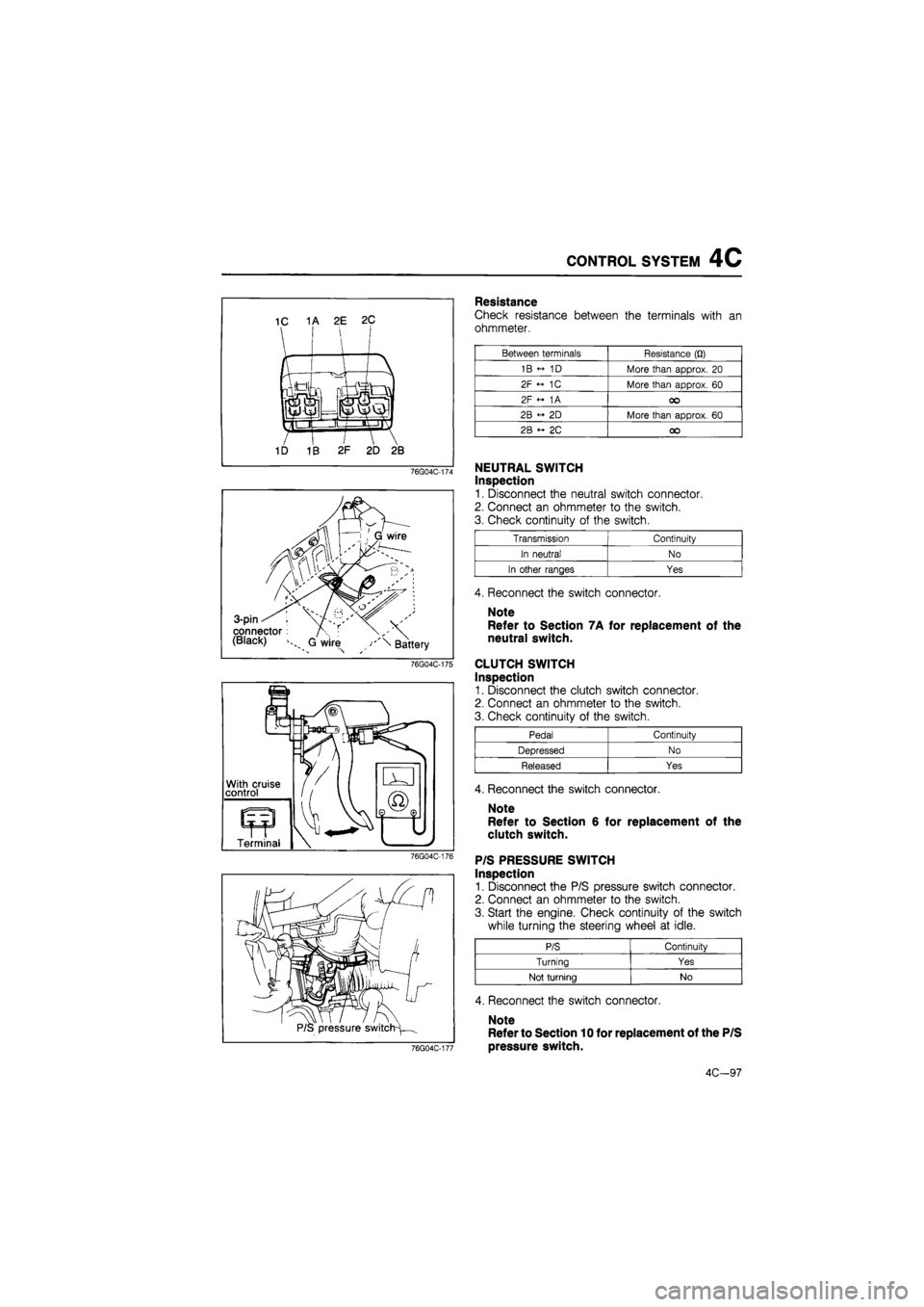
Check resistance between the terminals with an
ohmmeter.
Between terminals Resistance (Q)
1B « 1D More than approx. 20
2F <- 1C More than approx. 60
2F « 1A oo
2B « 2D More than approx. 60
2B ~ 2C oo
NEUTRAL SWITCH
Inspection
1. Disconnect the neutral switch connector.
2. Connect an ohmmeter to the switch.
3. Check continuity of the switch.
Transmission Continuity
In neutral No
In other ranges Yes
4. Reconnect the switch connector.
Note
Refer to Section 7A for replacement of the
neutral switch.
CLUTCH SWITCH
Inspection
1. Disconnect the clutch switch connector.
2. Connect an ohmmeter to the switch.
3. Check continuity of the switch.
Pedal Continuity
Depressed No
Released Yes
4. Reconnect the switch connector.
Note
Refer to Section 6 for replacement of the
clutch switch.
P/S PRESSURE SWITCH
Inspection
1. Disconnect the P/S pressure switch connector.
2. Connect an ohmmeter to the switch.
3. Start the engine. Check continuity of the switch
while turning the steering wheel at idle.
P/S Continuity
Turning Yes
Not turning No
4. Reconnect the switch connector.
Note
Refer to Section 10 for replacement of the P/S
pressure switch.
4C-97
Page 811 of 1865

TROUBLESHOOTING GUIDE 7A
TROUBLESHOOTING GUIDE
Problem Possible cause Remedy Page
Change lever won't Seized change lever ball Replace 7A-58 shift smoothly, or is Seized change control rod joint Replace 7A-58
hard to shift Bent change control rod Replace 7A-58
Too much play in Worn change control rod bushing Replace 7A-58 change lever Weak spring of ball or change lever Replace 7A-58 Worn bushing of ball or change lever Replace 7A—58
Difficult to shift Bent change rod Replace 7A—58
No grease in transmission control Lubricate with grease 7A-58
Insufficient oil Add oil 7A-6
Deterioration of oil quality Replace with oil of 7A-6 specified quality
Wear or play of shift fork or shift rod Replace 7 A—18
Wear of synchronizer ring Replace 7A-27
Wear of synchronizer cone of gear Replace 7A-27
Bed contact of synchronizer ring and cone of Replace 7A-27 gear
Excessive longitudinal play of gears Replace 7A-22
Wear of bearing Adjust or replace 7A—22
Wear of synchronizer key spring Replace 7A-27
Excessive shaft gear bearing preload Adjust 7A-37
Improperly adjusted change guide plate Adjust 7A-20
Won't stay in gear Bent change control rod Replace 7A-58
Worn change control rod bushing Replace 7A-58
Weak change lever ball spring Replace 7A-58
Improperly installed extension bar Tighten 7A-58
Wear of shift fork Replace 7A—22
Wear of clutch hub Replace 7A-27
Worn clutch hub sleeve Replace 7A-27
Worn gear sliding part of both shaft gears Replace 7A-26
Worn gear sliding part of each gear Replace 7A-26
Worn steel sliding groove of control end Replace 7 A—18
Weak spring pressing against steel ball Replace 7A-18
Excessive thrust clearance Replace 7A—33,35
Worn bearing Replace 7A—22
Improperly installed engine mount Tighten 7A—49
Abnormal noise Insufficient oil Add oil 7A-6
Deterioration of oil quality Replace 7A-6
Worn bearing Adjust or replace 7A-22
Worn gear sliding surface of both shaft gears Replace 7A—26
Wear of sliding surfaces of gears Replace 7A-26
Excessive thrust clearance Replace 7A—33,35
Damaged gear teeth Replace with oil of 7A-26
specified quality Foreign material in gears Replace 7A-22
Damaged differential gear, or excessive backlash Adjust or replace 7A—30
76G07A-005
7A-5
Page 852 of 1865
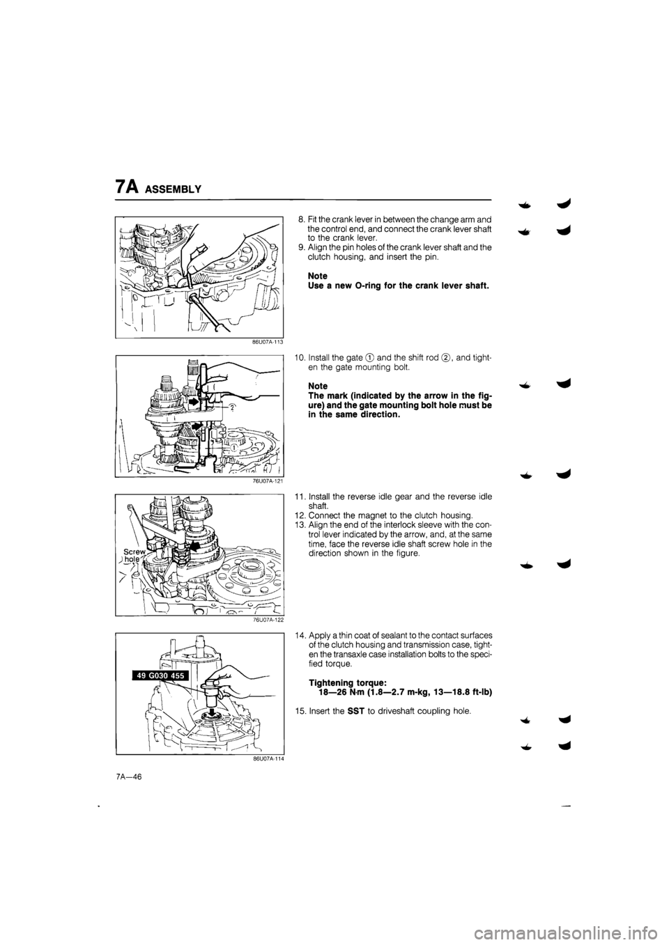
7A ASSEMBLY
8. Fit the crank lever in between the change arm and
the control end, and connect the crank lever shaft
to the crank lever.
9. Align the pin holes of the crank lever shaft and the
clutch housing, and insert the pin.
Note
Use a new O-ring for the crank lever shaft.
86U07A-113
10. Install the gate © and the shift rod ©, and tight-
en the gate mounting bolt.
Note
The mark (indicated by the arrow in the fig-
ure) and the gate mounting bolt hole must be
in the same direction.
76U07A-121
11. Install the reverse idle gear and the reverse idle
shaft.
12. Connect the magnet to the clutch housing.
13. Align the end of the interlock sleeve with the con-
trol lever indicated by the arrow, and, at the same
time, face the reverse idle shaft screw hole in the
direction shown in the figure.
76U07A-122
14. Apply a thin coat of sealant to the contact surfaces
of the clutch housing and transmission case, tight-
en the transaxle case installation bolts to the speci-
fied torque.
Tightening torque:
18—26 N m (1.8—2.7 m-kg, 13—18.8 ft-lb)
15. Insert the SST to driveshaft coupling hole.
7A-46
Page 868 of 1865
7B OUTLINE
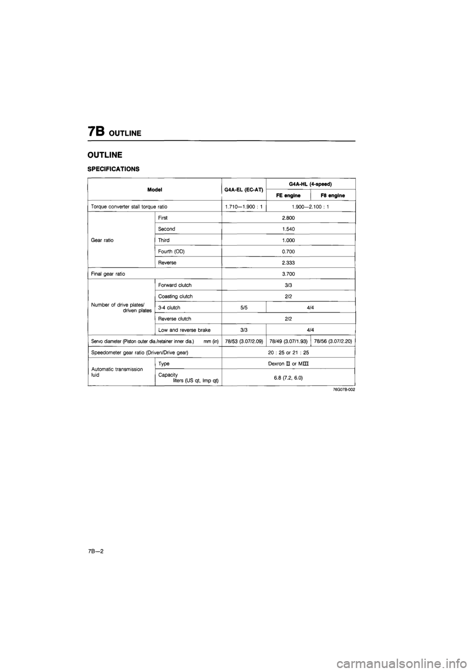
OUTLINE
SPECIFICATIONS
Model G4A-EL (EC-AT) G4A-HL (4-speed) Model G4A-EL (EC-AT)
FE engine F8 engine
Torque converter stall torque ratio 1.710—1.900
: 1
1.900-2.100
: 1
Gear ratio
First 2.800
Gear ratio
Second 1.540
Gear ratio Third 1.000 Gear ratio
Fourth (OD) 0.700
Gear ratio
Reverse 2.333
Final gear ratio 3.700
Number
of
drive plates/ driven plates
Forward clutch 3/3
Number
of
drive plates/ driven plates
Coasting clutch 2/2
Number
of
drive plates/ driven plates 3-4 clutch 5/5 4/4 Number
of
drive plates/ driven plates
Reverse clutch 2/2
Number
of
drive plates/ driven plates
Low and reverse brake 3/3 4/4
Servo diameter (Piston outer dia./retainer inner dia.) mm (in) 78/53 (3.07/2.09) 78/49 (3.07/1.93) 78/56 (3.07/2.20)
Speedometer gear ratio (Driven/Drive gear) 20
: 25 or
21
: 25
Automatic transmission luid
Type Dexron
n or
MED
Automatic transmission luid Capacity
liters (US qt, Imp
qt)
6.8 (7.2, 6.0)
76G07B-002
7 B—2