torque MAZDA 626 1987 Workshop Manual
[x] Cancel search | Manufacturer: MAZDA, Model Year: 1987, Model line: 626, Model: MAZDA 626 1987Pages: 1865, PDF Size: 94.35 MB
Page 6 of 1865
G FUNDAMENTAL PROCEDURES
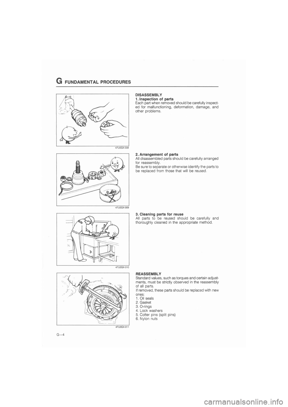
DISASSEMBLY
1. Inspection of parts
Each part when removed should be carefully inspect-
ed for malfunctioning, deformation, damage, and
other problems.
2. Arrangement of parts
All disassembled parts should be carefully arranged
for reassembly.
Be sure to separate or otherwise identify the parts to
be replaced from those that will be reused.
3. Cleaning parts for reuse
All parts to be reused should be carefully and
thoroughly cleaned in the appropriate method.
REASSEMBLY
Standard values, such as torques and certain adjust-
ments, must be strictly observed in the reassembly
of all parts.
If removed, these parts should be replaced with new
ones:
1. Oil seals
2. Gasket
3. O-rings
4. Lock washers
5. Cotter pins (split pins)
6. Nylon nuts
G—4
Page 11 of 1865
CHASSIS NUMBER LOCATION/ABBREVIATIONS/UNITS G
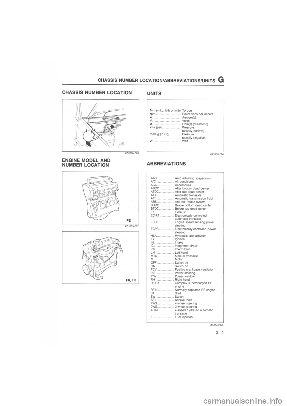
CHASSIS NUMBER LOCATION UNITS
67U0GX-005
ENGINE MODEL AND
NUMBER LOCATION
Nm (m-kg, ft-lb or in-lb). Torque
rpm Revolutions per minute A Ampere(s) V Volt(s) U Ohm(s) (resistance) kPa (psi) Pressure
(usually positive) mrriHg (in Hg) Pressure
(usually negative) W Watt
76G0GX-004
ABBREVIATIONS
67U0GX-007
AAS Auto adjusting suspension A/C Air conditioner ACC Accessories ABDC After bottom dead center ATDC After top dead center ATX Automatic transaxle ATF Automatic transmission fluid ABS Anti-lock brake system BBDC Before bottom dead center BTDC Before top dead center EX Exhaust EC-AT Electronically controlled automatic transaxle ESPS Engine speed sensing power steering EC PS Electronically-controlled power steering HLA Hydraulic lash adjuster IG Ignition IN Intake IC Integrated circuit INT Intermittent LH Left hand
MTX Manual transaxle M Motor OFF Switch off ON Switch on PCV Positive crankcase ventilation P/S Power steering P/W Power window RH Right hand RF-CX Comprex supercharged RF
engine
RF-N Normally aspirated RF engine ST Start sw Switch SST Special tools 4WS 4-wheel steering
PWS 2-wheel steering
4HAT 4-speed hydraulic automatic
transaxle Fl Fuel injection
76GQGX-005
G—9
Page 39 of 1865
1A TUNE-UP PROCEDURE
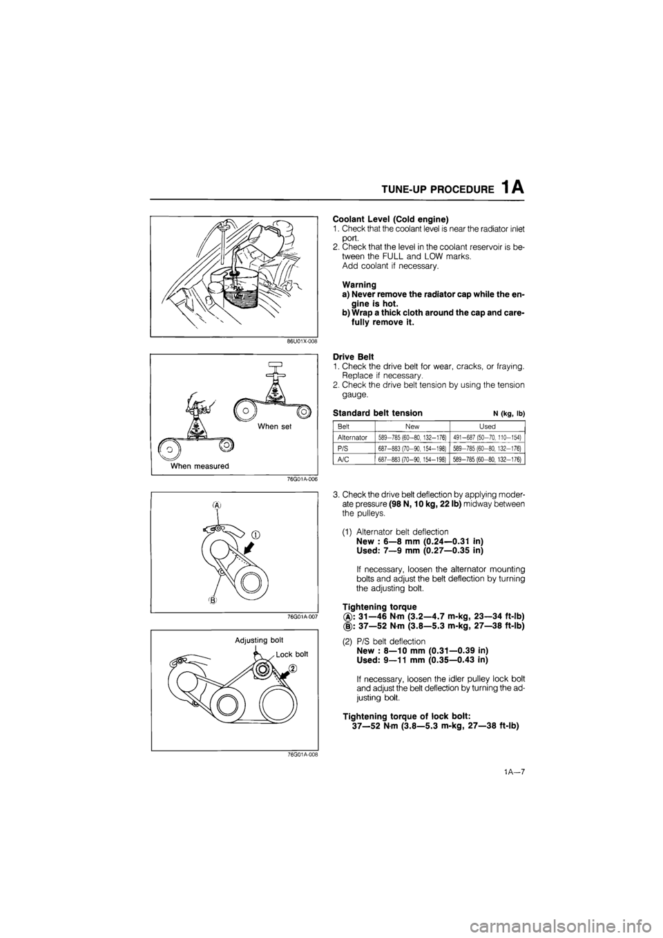
Coolant Level (Cold engine)
1. Check that the coolant level is near the radiator inlet
port.
2. Check that the level in the coolant reservoir is be-
tween the FULL and LOW marks.
Add coolant if necessary.
Warning
a) Never remove the radiator cap while the en-
gine is hot.
b) Wrap a thick cloth around the cap and care-
fully remove it.
86U01X-008
When set
When measured
Drive Belt
1. Check the drive belt for wear, cracks, or fraying.
Replace if necessary.
2. Check the drive belt tension by using the tension
gauge.
Standard belt tension N (kg, lb)
Belt New Used
Alternator 589-785 (60-80, 132-176) 491-687 (50-70, 110-154)
P/S 687-883 (70-90, 154-198) 589-785 (60-80, 132-176)
A/C 687-883 (70-90,154-198) 589-785 (60-80, 132-176)
76G01A-006
76G01A-007
Adjusting bolt
3. Check the drive belt deflection by applying moder-
ate pressure (98 N, 10 kg, 22 lb) midway between
the pulleys.
(1) Alternator belt deflection
New : 6—8 mm (0.24—0.31 in)
Used: 7—9 mm (0.27—0.35 in)
If necessary, loosen the alternator mounting
bolts and adjust the belt deflection by turning
the adjusting bolt.
Tightening torque
31—46 Nm (3.2—4.7 m-kg, 23—34 ft-lb)
(§): 37—52 Nm (3.8—5.3 m-kg, 27—38 ft-lb)
(2) P/S belt deflection
New : 8—10 mm (0.31—0.39 in)
Used: 9—11 mm (0.35—0.43 in)
If necessary, loosen the idler pulley lock bolt
and adjust the belt deflection by turning the ad-
justing bolt.
Tightening torque of lock bolt:
37—52 Nm (3.8—5.3 m-kg, 27—38 ft-lb)
76G01A-019
1A—7
Page 40 of 1865
1A TUNE-UP PROCEDURE
76G01A-009
76G01A-010
Wear and adhesion of carbon
Burnt
Damage and
deterioration
Damage
76G01A-011
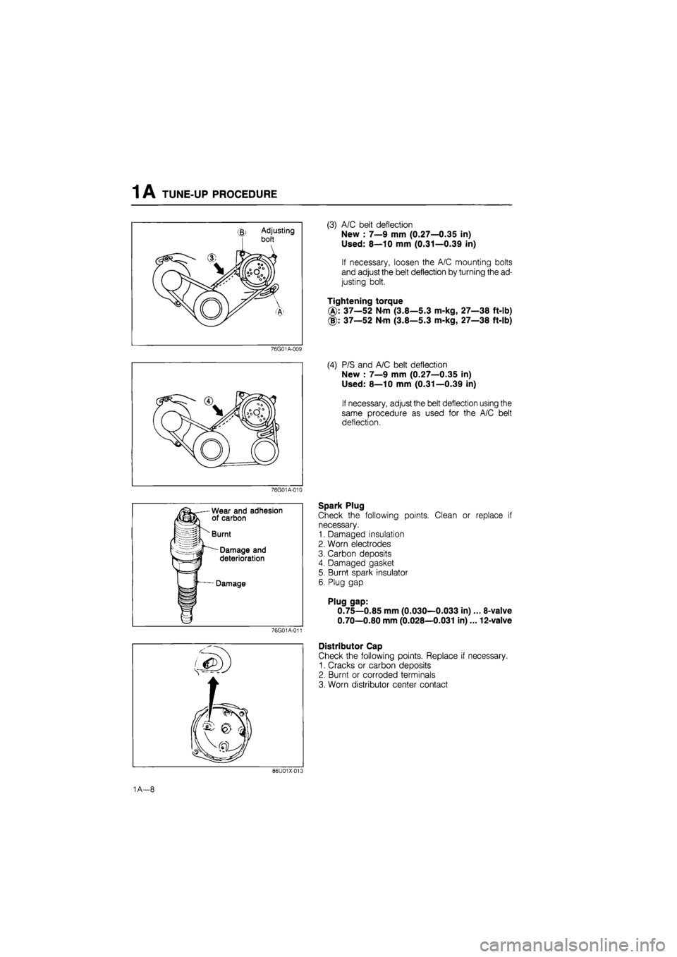
(3) A/C belt deflection
New : 7—9 mm (0.27—0.35 in)
Used: 8—10 mm (0.31—0.39 in)
If necessary, loosen the A/C mounting bolts
and adjust the belt deflection by turning the ad-
justing bolt.
Tightening torque
37—52 Nm (3.8—5.3 m-kg, 27—38 ft-lb)
(§): 37—52 Nm (3.8—5.3 m-kg, 27—38 ft-lb)
(4) P/S and A/C belt deflection
New : 7—9 mm (0.27—0.35 in)
Used: 8—10 mm (0.31—0.39 in)
If necessary, adjust the belt deflection using the
same procedure as used for the A/C belt
deflection.
Spark Plug
Check the following points. Clean or replace if
necessary.
1. Damaged insulation
2. Worn electrodes
3. Carbon deposits
4. Damaged gasket
5. Burnt spark insulator
6. Plug gap
Plug gap:
0.75—0.85 mm (0.030—0.033 in)... 8-valve
0.70—0.80 mm (0.028—0.031 in)... 12-valve
Distributor Cap
Check the following points. Replace if necessary.
1. Cracks or carbon deposits
2. Burnt or corroded terminals
3. Worn distributor center contact
86U01X-013
1A—8
Page 48 of 1865

1 A ON-VEHICLE MAINTENANCE (TIMING BELT)
Installation
Install in the reverse order of removal referring to the installation note.
Torque Specifications
76G01
A-109
7—10
N-m
(70—100 cm-kg, 61—87 in-lb)
7—10 N-m (70—100 em-kg, 61—87 In-lb)
12—17
N-m
(1.25—1.75 m-kg, 109—152 in-lb)
8-11 N-m (80—110 cm-kg,
Installation note
Timing belt
1. Check that the mark on the timing belt pulley is
aligned with the mating mark.
86U01X-220
1A—16
Page 50 of 1865

1 A ON-VEHICLE MAINTENANCE (TIMING BELT)
8. Tighten the timing belt tensioner lock bolt.
Tightening torque:
37—52 N-m (3.8—5.3 m-kg, 27—38 ft-lb)
69G01B-028
9. Check the timing belt deflection. If the deflection
is not correct, repeat the adjustment from step 5
above.
Timing belt deflection
FE: 5.5—6.5 mm (0.22—0.26 in)
F8, F6: 4.0—5.0 mm (0.16—0.20 in)
/98 N (10 kg, 22 lb)
Caution
Be sure not to apply tension other than that
of the tensioner spring.
76G01A-029
Baffle plate
Install the baffle plate as shown in the figure.
69G01B-030
Drive belt
Install each drive belt, and check the belt deflection.
(Refer to page 1A—7.)
76G01A-030
1A—18
Page 51 of 1865

1 A ON-VEHICLE MAINTENANCE (TIMING BELT)
Spark plug
1. Apply anti-seize compound or molybdenum-based
lubricant to the spark plug threads.
2. Install the spark plugs.
Tightening torque:
15—23 N-m (1.5—2.3 m-kg, 11—17 ft-lb)
79G01C-021
Steps After Installation
Perform the necessary engine adjustment. (Refer to
TUNE-UP PROCEDURE.)
86U01X-029
1A—19
Page 55 of 1865

ON-VEHICLE MAINTENANCE (CYLINDER HEAD) 1 A
Installation
Install in the reverse order of removal referring to the installation note.
Note a) Position the hose clamp in the original location on the hose.
b) Squeeze the clamp lightly with large pliers to ensure a good fit.
Torque Specifications
19—30
N
m (1.9—3.1 m-kg/' 14—22 ft-lb)
37—63
N m
(3.8—6.4 m-kg 27-46 ft-lb)
37—52 Nm (3.8 27—1
31—46 N-m (3.2—<
Page 56 of 1865

1 A ON-VEHICLE MAINTENANCE (CYLINDER HEAD)
Installation note
Cylinder head
1. Thoroughly remove all dirt and oil from the top of
the cylinder block with a rag.
2. Place a new cylinder head gasket in position.
86U01X-035
®
CD
© (8)
3. Set the cylinder head in place.
4. Apply engine oil to the bolt threads and seat faces.
5. Tighten the cylinder head bolts in two or three steps
in the order shown in the figure.
Tightening torque:
80—86 N-m (8.2—8.8 m-kg, 59—64 ft-lb)
86U01X-036
Cylinder head cover
1. Apply silicon sealant to the shaded area shown in
the figure.
2. Install the cylinder head cover.
Tightening torque:
6—8
N
m (60—80 cm-kg, 52—69 in-lb)
86U01X-037
Timing belt
1. Align the mating mark of the camshaft pulley with
the front housing timing mark.
Note
For FE engine, align "2" mark.
For F8, F6 engine, align "3" mark.
2. Install the timing belt. (Refer to TIMING BELT of
ON-VEHICLE MAINTENANCE.)
76G01A-034
1A—24
Page 61 of 1865
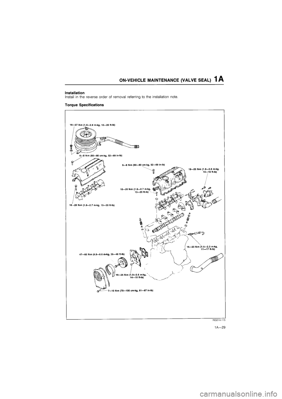
1 A ON-VEHICLE MAINTENANCE (VALVE SEAL)
Installation
Install in the reverse order of removal referring to the installation note.
Torque Specifications
16—27 N-m (1.6—2.8 m-kg, 12—20 ft-lb)
76G01A-115
1A—29