spark plugs MAZDA 626 1987 Workshop Manual
[x] Cancel search | Manufacturer: MAZDA, Model Year: 1987, Model line: 626, Model: MAZDA 626 1987Pages: 1865, PDF Size: 94.35 MB
Page 14 of 1865
0 PRE-DELIVERY INSPECTION
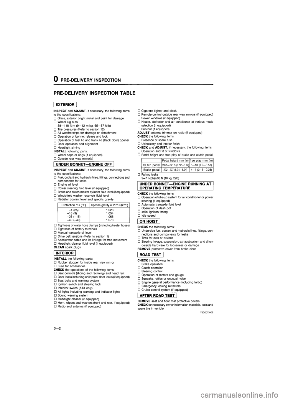
PRE-DELIVERY INSPECTION TABLE
EXTERIOR
INSPECT and ADJUST, if necessary, the following items
to the specifications:
• Glass, exterior bright metal and paint for damage
• Wheel lug nuts
88—118 N m (9—12 m-kg, 65—87 ft-lb)
• Tire pressures (Refer to section 12)
• All weatherstrips for damage or detachment
• Operation of bonnet release and lock
• Operation of fuel lid and trunk lid (Back door) opener
• Door operation and alignment
• Headlight aiming
INSTALL following parts:
• Wheel caps or rings (if equipped)
• Outside rear view mirror(s)
UNDER BONNET—ENGINE OFF
INSPECT and ADJUST, if necessary, the following items
to the specifications:
• Fuel, coolant and hydraulic lines, fittings, connections and
components for leaks
• Engine oil level
• Power steering fluid level (if equipped)
• Brake and clutch master cylinder fluid level (if equipped)
• Windshield washer reservoir fluid level
• Radiator coolant level and specific gravity
Protection °C (°F) Specific gravity at 20°C (68°F)
-4 (25) 1.028
-16(3) 1.054
-26 (-15) 1.066 -40 (-40) 1.078
• Tightness of water hose clamps (including heater hoses)
• Tightness of battery terminals
• Manual transaxle oil level
• Drive belt tensions (Refer to section 1)
• Accelerator cable and its linkage for free movement
• Headlight cleaner fluid level (if equipped)
CLEAN spark plugs
INTERIOR
INSTALL the following parts:
• Rubber stopper for inside rear view mirror
• Fuse for accessories
CHECK the operations of the following items:
• Seat controls (sliding and reclining) and head rest
• Door locks including childproof door locks (if equipped)
• Seat belts and warning system
• Ignition switch and steering lock
• Inhibitor switch (ATX only)
• All lights including warning and indicator lights
• Sound warning system
• Headlight cleaner (if equipped)
• Horn, wipers and washers (front and rear, if equipped)
• Radio and antenna (if equipped)
• Cigarette lighter and clock
• Remote control outside rear view mirrors (if equipped)
• Power windows (if equipped)
• Heater, defroster and air conditioner at various mode
selection (if equipped)
• Sunroof (if equipped)
ADJUST antenna trimmer on radio (if equipped)
CHECK the following items:
• Presence of spare fuse
• Upholstery and interior finish
CHECK and ADJUST, if necessary, the following items:
• Operation and fit of windows
• Pedal height and free play of brake and clutch pedal
Pedal height mm (in) free play mm (in)
Clutch pedal 216.5-221.5 (8.52-8.72) 5-13 (0.2-0.51)
Brake pedal 222-227 (8.74-8.94) 4-7 (0.16-0.28)
• Parking brake
5-7 noches/98 N (10 kg, 22lb)
UNDER BONNET—ENGINE RUNNING AT
OPERATING TEMPERATURE
CHECK the following items:
• Operation of idle-up system for air conditioner or power
steering (if equipped)
• Automatic transaxle fluid level
• Operation of dash pot
• Initial ignition timing
• Idle speed
ON HOIST
CHECK the following items:
• Underside fuel, coolant and hydraulic lines, fittings, con-
nections and components for leaks
• Tires for cuts or bruises
• Steering linkage, suspension, exhaust system and all un-
derside hardware for looseness or damage
REMOVE protective cover from brake discs
ROAD TEST"
CHECK the following items:
• Brake operation
• Clutch operation
• Steering control
• Operation of meters and gauge
• Squeaks, rattles or unusual noise
• Engine general performance (including turbo)
• Emergency locking retractors
• Cruise control system (if equipped)
AFTER ROAD TEST
REMOVE seat and floor mat protective covers
CHECK for necessary owner information materials, tools and
spare tire in vehicle
-76G00X-002
0-2
Page 18 of 1865

0 1 C5
Interval
Procedure & item
Number of Months or km, whichever corns first
Months
x 1000 Km
Miles x 1000
Fuel lines and hoses
Spark plugs
Initial ignition timing
Idle speed
Idle mixture
Dash pot (MTX)
0.6
6
10
12
20
12
18
30
18
24
40
24
30
50
30
36
60
36
42
70
42
48
80
48
©1
O
o
o
o
o
o
©2
O
o
o
o
o
o
©3
O
O
O
O
O
©4
O
Service data and inspection point
Fittings, connections and compo-
nents for leaks
Plug gap: F8, FE (8-VALVE) 0.75—0.85 mm (0.030—0.033 in) FE (12-VALVE) FE (DOHC) 0.7—0.8 mm (0.028—0.031 in) Recommended spark plugs
F6,F8,FE 8-VALVE FE 12-VALVE DOHC
NGK BPR 5ES
BPR 6ES
BCPR 5E BCPR 6E
Nippon
Denso
W16EXR-U
W20EXR-U
Q16PR-U* Q20PR-U
Initial ignition timing 6 ±
1
° BTDC 12 ± 1° BTDC (FE DOHC)
Check the idle speed (rpm) FE DOHC 700—800 Carburetor MTX 800—850, ATX 900—950 (N range)
CO concentration FE DOHC 1.5 ±0.5 % Others 2.0 ± 0.5 % HC concentration FE DOHC Less than 1000 rpm
Operation
Page
4B—42
5-9
5-11
4A-38 4C-29
4A-38 4C—30
4A-50
4B-67
m z >
z o m
H >
00 I-m
m o m
i-CD 0) Q. (D o.
5'
0 1 m a
m D
m z >
z o m
Only FE 12-VALVE
G)
o o o>
Page 24 of 1865
o
r\3
Interval
Procedure & item
Number of Months or km, whichever corns first
Months
x
1000 Km
Miles x 1000
Fuel filter (R) for carbretor model
Fuel lines and hoses
Spark plugs
Initial ignition timing
Idle Speed
E.G.R. System
Evaporative system (if equipped)
O) O
X o
Choke system
0.6
6
10
12
20
12
(R)
18
30
18
24
40
24
30
50
30
36
60
36
(R)
42
70
42
48
80
48
©1
O
O
o
o
o
o
o
o
o
o
o
o
o
o
©3
o
o
o
o
o
o
o
©4
o
o
Service data and inspection point
Fittings, connections and compo-
nents for leaks
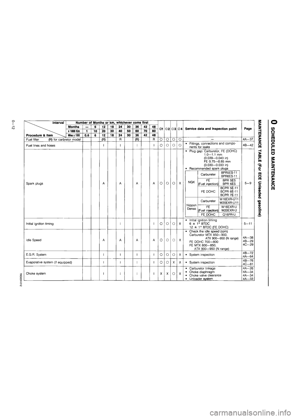
Plug gap: Carburetor, FE (DOHC) 1.0—1.1 mm (0.039—0.043 in) FE 0.75—0.85 mm (0.030-0.033 in) Recommended spark plugs
NGK
Carbureter BPR5ES-11 BPR6ES-11
NGK FE
(Fuel injection)
BPR 5ES
BPR 6ES NGK
FE DOHC
BCPR 5E-11 BCPR 6E-11 BCPR 7E-11
Nippon Denso
Carbureter W16EXR-U11 W20EXR-U11 Nippon Denso FE
(Fuel injection)
W16EXR-U
W20EXR-U
Nippon Denso
FE DOHC Q16PR-U
Initial ignition timing
6 ±
1
° BTDC
12 ± 1° BTDC (FE DOHC)
Check the idle speed (rpm) Carburetor MTX 850—900,
ATX 900-950 (N range) FE DOHC 700-800 FE MTX 800—850,
ATX 900-950 (N range)
System inspection
System inspection
Carburetor linkage Choke diaphragm Choke valve clearance Unloader system
Page
4A-37
4B-42
5-9
5-11
4A—38 4B-29 4C—29
4B—72 4A—64
4B—76
4C-81
4A-26 4A—34 4A—34 4A—33
m z >
z o m
H >
00 r-m
H o
m O m
3
CO o X m a c i-m a
m z >
z o m
Page 30 of 1865
Interval
Procedure & item
Number of Months or km, whichever corns first
Months
x 1000 Km
Miles x 1000
Engine oil
Oil filter
Fuel filter (R) only for carbretor
Fuel lines and hoses (I) only for Diesel
Spark plugs
Initial ignition timing
Idle speed (I) only for carbretor
0.6
(I)
6
10
(0
12
20
12
(R)
18
30
18
(I)
24
40
24
30
50
30
(I)
36
60
36
(R)
42
70
42
(I)
48
80
48
®1
O
o
o
o
o
o
o
©2
O
o
o
o
o
o
o
©3
O
o
o
o
o
o
©4
O
o
o
Service data and inspection point
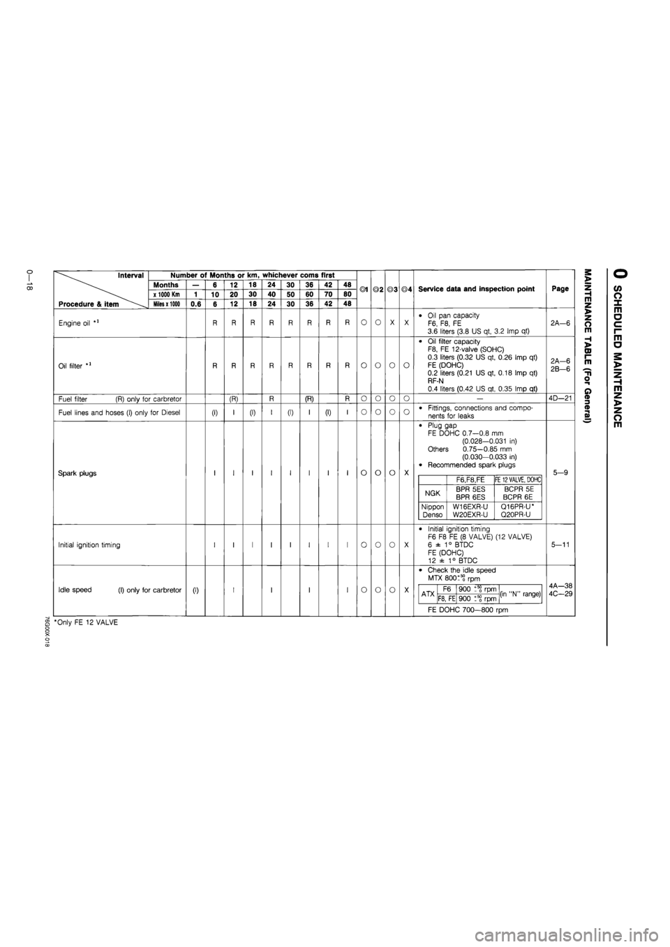
Oil pan capacity F6, F8, FE 3.6 liters (3.8 US qt, 3.2 Imp qt)
Oil filter capacity F8, FE 12-valve (SOHC)
0.3 liters (0.32 US qt, 0.26 Imp qt)
FE (DOHC) 0.2 liters (0.21 US qt, 0.18 Imp qt) RF-N
0.4 liters (0.42 US qt, 0.35 Imp qt)
Fittings, connections and compo-
nents for leaks
Plug gap FE DOHC 0.7—0.8 mm (0.028-0.031 in) Others 0.75—0.85 mm (0.030—0.033 in) Recommended spark plugs
F6,F8,FE FE
12 VALVE,
DOHC
NGK BPR 5ES BPR 6ES BCPR 5E
BCPR 6E
Nippon
Denso W16EXR-U
W20EXR-U
Q16PR-U* Q20PR-U
Initial ignition timing F6 F8 FE (8 VALVE) (12 VALVE)
6 ±
1
° BTDC FE (DOHC) 12 ± 1° BTDC
Check the idle speed
MTX 80015? rpm
ATX F6 900 rpm (in "N" range) ATX F8, FE 900 t5? rpm (in "N" range)
FE DOHC 700—800 rpm
§ *Only FE 12 VALVE
Page
2A—6
2A-6
2B-6
4D—21
5-9
5-11
4A—38
4C-29
m z >
z o m
H >
CD I-m
T1
o
o
m z >
z o m
Page 45 of 1865

ON-VEHICLE INSPECTION 1 A
ON-VEHICLE INSPECTION
If the engine exhibits low power, poor fuel economy,
or poor idle, check the following points.
1. Ignition system (Refer to Section 5)
2. Compression
3. Fuel system (Refer to Section 4)
COMPRESSION
1. Check that the battery is fully charged. Recharge
if necessary.
76G01A-107
2. Warm up the engine to the normal operating tem-
perature.
3. Turn it off for about 10 minutes to allow the exhaust
manifold to cool.
4. Remove all spark plugs.
5. Disconnect the primary wire connector from the
ignition coil.
86U01X-020
6. Connect a compression gauge to No.
1
spark plug
hole.
7. Fully depress the accelerator pedal and crank the
engine.
8. Note the maximum gauge reading.
9. Check each cylinder.
Compression pressure kPa (kg/cm2, psi)-rpm
Standard Minimum
F6 1,128 (11.5, 164)—270 790 (8.1, 114)—270
F8-FE 1,275 (13.0, 185)—270 893 (9.1, 129)—270
FE 12-valve 1,422 (14.5, 206)—280 996 (10.2, 144)—280
76G01A-023
Possible Cause
86U01X-022
1A—13
Page 51 of 1865

1 A ON-VEHICLE MAINTENANCE (TIMING BELT)
Spark plug
1. Apply anti-seize compound or molybdenum-based
lubricant to the spark plug threads.
2. Install the spark plugs.
Tightening torque:
15—23 N-m (1.5—2.3 m-kg, 11—17 ft-lb)
79G01C-021
Steps After Installation
Perform the necessary engine adjustment. (Refer to
TUNE-UP PROCEDURE.)
86U01X-029
1A—19
Page 120 of 1865

1 A ASSEMBLY (AUXILIARY PARTS)
86U01X-169
86U01X-219
76G01A-035
Thermostat and Thermostat Cover
1. Install the thermostat into the cylinder head with
the jiggle pin at the top.
2. Position a new gasket with the printed side facing
the cylinder head.
3. Install the thermostat cover.
Tightening torque:
19—30 Nm (1.9—3.1 m-kg, 14—22 ft-lb)
Spark Plug
1. Apply anti-seize compound or molybdenum-based
lubricant to the spark plug threads.
2. Install the spark plugs.
Tightening torque:
15—23 Nm (1.5—2.3 m-kg, 11—17 ft-lb)
Distributor
1. Apply engine oil to the O-ring, and position it on
the distributor.
2. Apply engine oil to the blade or gear.
3. Align the mating marks as shown in the figure
...8-valve.
4. Install the distributor with the marks facing straight
up.
5. Loosely tighten the distributor mounting bolt.
High-Tension Lead
Install the high-tension leads.
Engine Mount Bracket
Install the engine mount.
Tightening torque:
85—117 Nm (8.7—11.9 m-kg, 63—86 ft-lb)
86U01X-178
1A—88
Page 141 of 1865
1 B ON-VEHICLE INSPECTION
76G01B-017
86U01X-020
76G01B-018
Possible Cause
ON-VEHICLE INSPECTION
If the engine exhibits low power, poor fuel economy,
or poor idle, check the following points.
1. Ignition system (Refer to Section 5)
2. Compression
3. Fuel system (Refer to Section 4C)
COMPRESSION
1. Check that the battery is fully charged. Recharge
if necessary.
2. Warm up the engine to the normal operating tem-
perature.
3. Turn it off for about 10 minutes to allow the exhaust
manifold to cool.
4. Remove all spark plugs.
5. Disconnect the primary wire connector from the
ignition coil.
6. Connect a compression gauge to No.1 spark plug
hole.
7. Fully depress the accelerator pedal and crank the
engine.
8. Note the maximum gauge reading.
9. Check each cylinder.
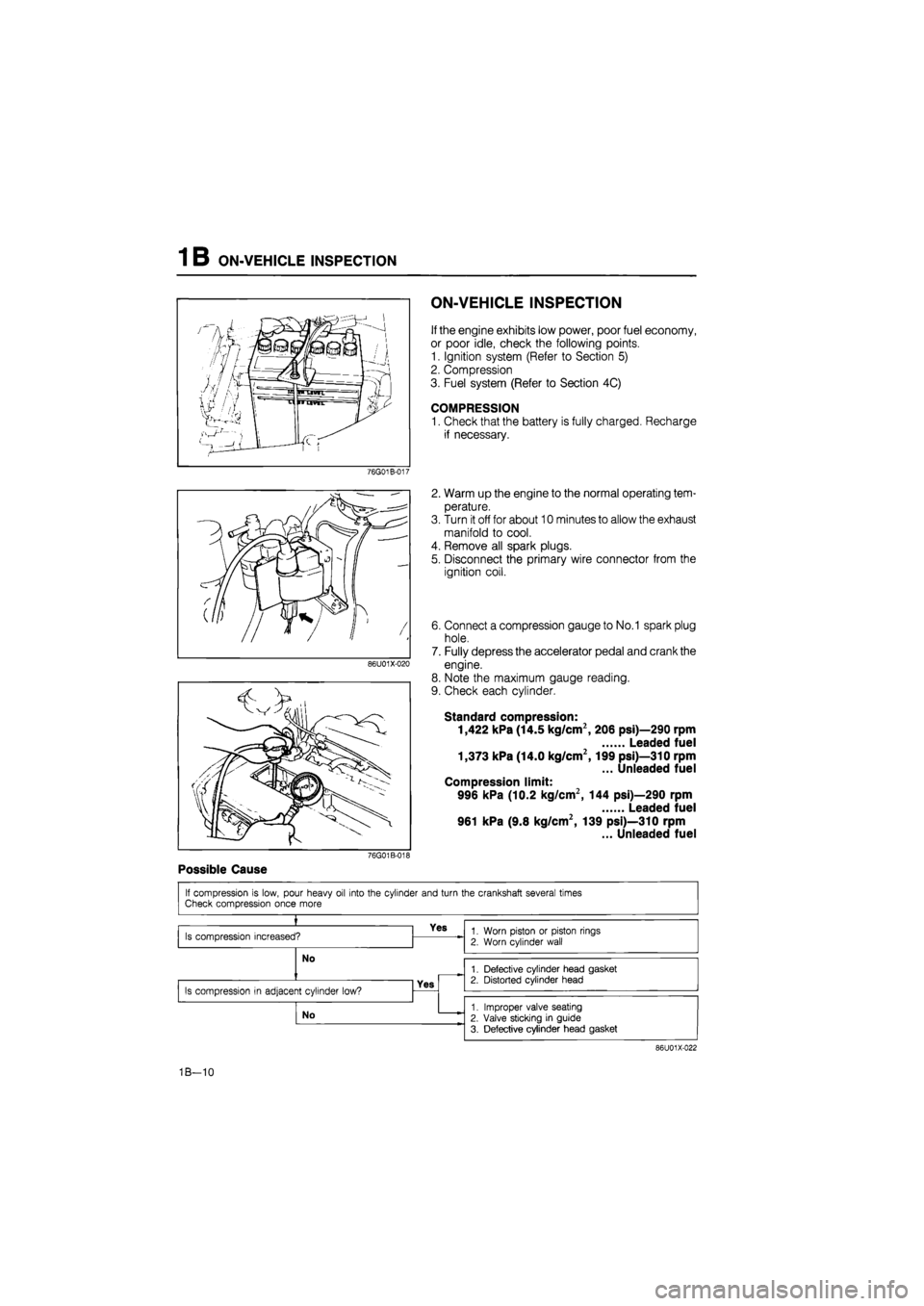
Standard compression:
1,422 kPa (14.5 kg/cm2, 206 psi)—290 rpm
Leaded fuel
1,373 kPa (14.0 kg/cm2,199 psi)—310 rpm
... Unleaded fuel
Compression limit:
996 kPa (10.2 kg/cm2, 144 psi)—290 rpm
Leaded fuel
961 kPa (9.8 kg/cm2, 139 psi)—310 rpm
... Unleaded fuel
If compression is low, pour heavy oil into the cylinder and turn the crankshaft several times Check compression once more
»
Is compression increased? Yes 1. Worn piston or piston rings
2. Worn cylinder wall
No
1. Worn piston or piston rings
2. Worn cylinder wall
No 1. Defective cylinder head gasket 2. Distorted cylinder head
Is compression in adjacent cylinder low? Yes
1. Defective cylinder head gasket 2. Distorted cylinder head
Is compression in adjacent cylinder low?
No 1. Improper valve seating
2. Valve sticking in guide
3. Defective cylinder head gasket
86U01X-022
1B—10
Page 146 of 1865
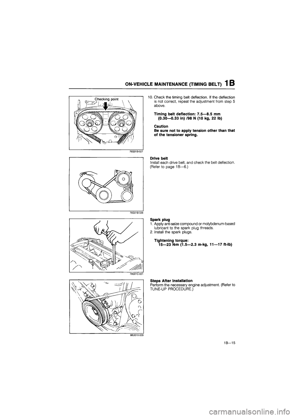
ON-VEHICLE MAINTENANCE (TIMING BELT) 1 B
10. Check the timing belt deflection. If the deflection
is not correct, repeat the adjustment from step 5
above.
Timing belt deflection: 7.5—8.5 mm
(0.30—0.33 in) /98 N (10 kg, 22 lb)
Caution
Be sure not to apply tension other than that
of the tensioner spring.
76G01B-027
Drive belt
Install each drive belt, and check the belt deflection.
(Refer to page 1B—6.)
76G01B-028
Spark plug
1. Apply anti-seize compound or molybdenum-based
lubricant to the spark plug threads.
2. Install the spark plugs.
Tightening torque:
15—23
N
m (1.5—2.3 m-kg, 11—17 ft-lb)
79G01C-021
Steps After Installation
Perform the necessary engine adjustment. (Refer to
TUNE-UP PROCEDURE.)
86U01X-029
1B—15
Page 201 of 1865
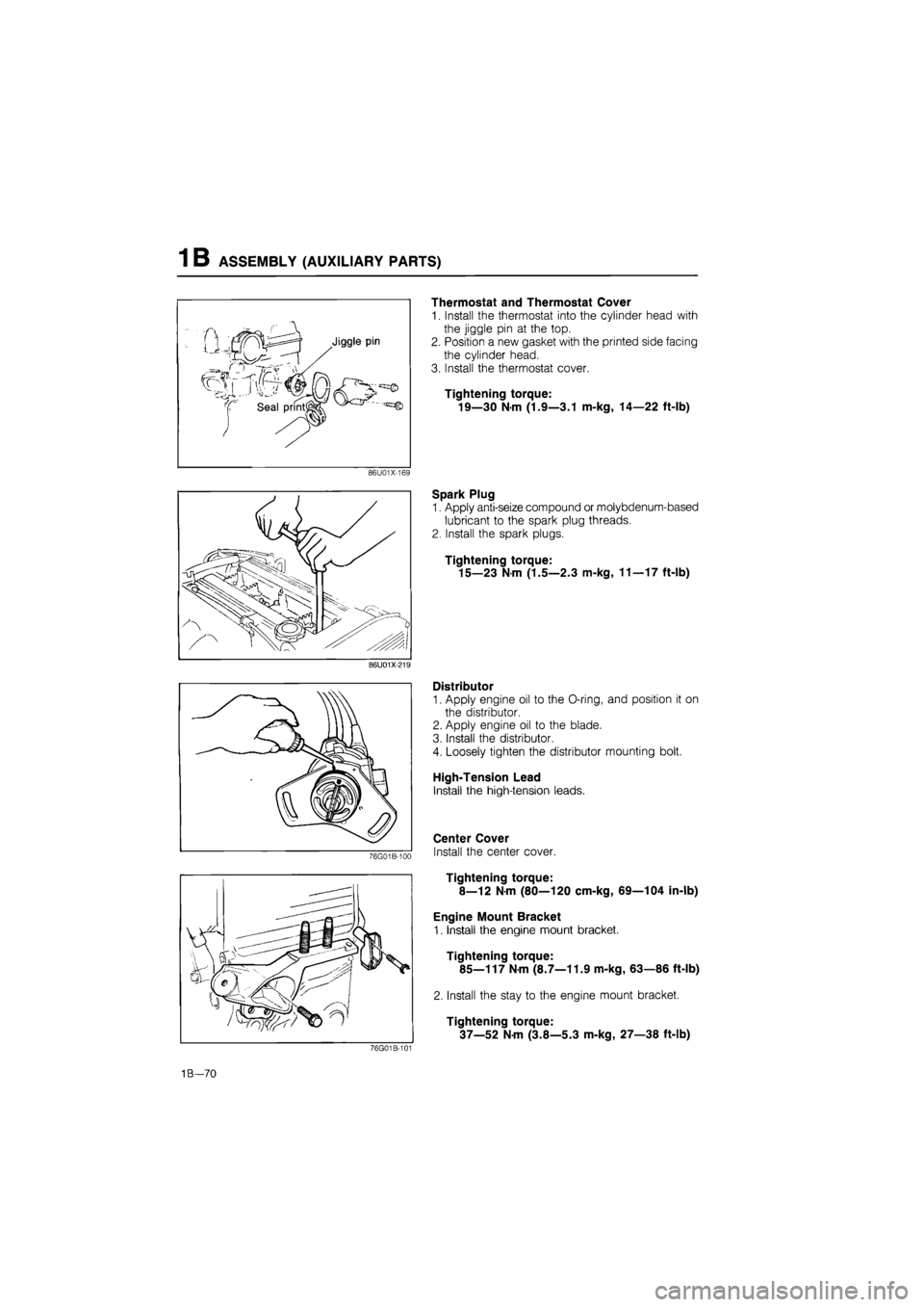
1 B ASSEMBLY (AUXILIARY PARTS)
Thermostat and Thermostat Cover
1. Install the thermostat into the cylinder head with
the jiggle pin at the top.
2. Position a new gasket with the printed side facing
the cylinder head.
3. Install the thermostat cover.
Tightening torque:
19—30 Nm (1.9—3.1 m-kg, 14—22 ft-lb)
86U01X-169
Spark Plug
1. Apply anti-seize compound or molybdenum-based
lubricant to the spark plug threads.
2. Install the spark plugs.
Tightening torque:
15—23
N
m (1.5—2.3 m-kg, 11—17 ft-lb)
86U01X-219
1B—70
Distributor
1. Apply engine oil to the O-ring, and position it on
the distributor.
2. Apply engine oil to the blade.
3. Install the distributor.
4. Loosely tighten the distributor mounting bolt.
High-Tension Lead
Install the high-tension leads.
Center Cover
Install the center cover.
Tightening torque:
8—12 Nm (80—120 cm-kg, 69—104 in-lb)
Engine Mount Bracket
1. Install the engine mount bracket.
Tightening torque:
85—117
N m
(8.7—11.9 m-kg, 63—86 ft-lb)
2. Install the stay to the engine mount bracket.
Tightening torque:
37—52
N
m (3.8—5.3 m-kg, 27—38 ft-lb)