warning lights MAZDA 626 1987 Workshop Manual
[x] Cancel search | Manufacturer: MAZDA, Model Year: 1987, Model line: 626, Model: MAZDA 626 1987Pages: 1865, PDF Size: 94.35 MB
Page 14 of 1865

0 PRE-DELIVERY INSPECTION
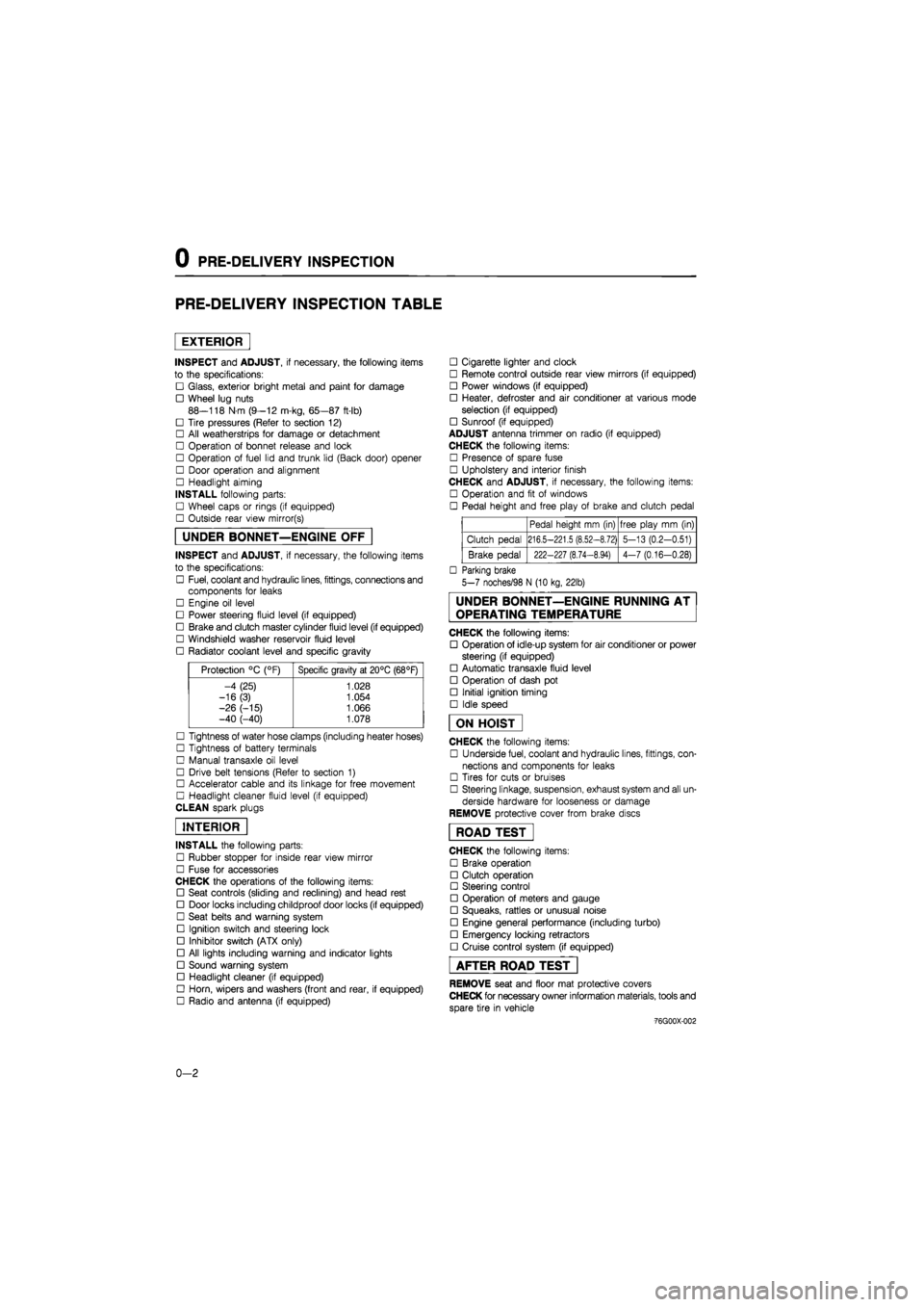
PRE-DELIVERY INSPECTION TABLE
EXTERIOR
INSPECT and ADJUST, if necessary, the following items
to the specifications:
• Glass, exterior bright metal and paint for damage
• Wheel lug nuts
88—118 N m (9—12 m-kg, 65—87 ft-lb)
• Tire pressures (Refer to section 12)
• All weatherstrips for damage or detachment
• Operation of bonnet release and lock
• Operation of fuel lid and trunk lid (Back door) opener
• Door operation and alignment
• Headlight aiming
INSTALL following parts:
• Wheel caps or rings (if equipped)
• Outside rear view mirror(s)
UNDER BONNET—ENGINE OFF
INSPECT and ADJUST, if necessary, the following items
to the specifications:
• Fuel, coolant and hydraulic lines, fittings, connections and
components for leaks
• Engine oil level
• Power steering fluid level (if equipped)
• Brake and clutch master cylinder fluid level (if equipped)
• Windshield washer reservoir fluid level
• Radiator coolant level and specific gravity
Protection °C (°F) Specific gravity at 20°C (68°F)
-4 (25) 1.028
-16(3) 1.054
-26 (-15) 1.066 -40 (-40) 1.078
• Tightness of water hose clamps (including heater hoses)
• Tightness of battery terminals
• Manual transaxle oil level
• Drive belt tensions (Refer to section 1)
• Accelerator cable and its linkage for free movement
• Headlight cleaner fluid level (if equipped)
CLEAN spark plugs
INTERIOR
INSTALL the following parts:
• Rubber stopper for inside rear view mirror
• Fuse for accessories
CHECK the operations of the following items:
• Seat controls (sliding and reclining) and head rest
• Door locks including childproof door locks (if equipped)
• Seat belts and warning system
• Ignition switch and steering lock
• Inhibitor switch (ATX only)
• All lights including warning and indicator lights
• Sound warning system
• Headlight cleaner (if equipped)
• Horn, wipers and washers (front and rear, if equipped)
• Radio and antenna (if equipped)
• Cigarette lighter and clock
• Remote control outside rear view mirrors (if equipped)
• Power windows (if equipped)
• Heater, defroster and air conditioner at various mode
selection (if equipped)
• Sunroof (if equipped)
ADJUST antenna trimmer on radio (if equipped)
CHECK the following items:
• Presence of spare fuse
• Upholstery and interior finish
CHECK and ADJUST, if necessary, the following items:
• Operation and fit of windows
• Pedal height and free play of brake and clutch pedal
Pedal height mm (in) free play mm (in)
Clutch pedal 216.5-221.5 (8.52-8.72) 5-13 (0.2-0.51)
Brake pedal 222-227 (8.74-8.94) 4-7 (0.16-0.28)
• Parking brake
5-7 noches/98 N (10 kg, 22lb)
UNDER BONNET—ENGINE RUNNING AT
OPERATING TEMPERATURE
CHECK the following items:
• Operation of idle-up system for air conditioner or power
steering (if equipped)
• Automatic transaxle fluid level
• Operation of dash pot
• Initial ignition timing
• Idle speed
ON HOIST
CHECK the following items:
• Underside fuel, coolant and hydraulic lines, fittings, con-
nections and components for leaks
• Tires for cuts or bruises
• Steering linkage, suspension, exhaust system and all un-
derside hardware for looseness or damage
REMOVE protective cover from brake discs
ROAD TEST"
CHECK the following items:
• Brake operation
• Clutch operation
• Steering control
• Operation of meters and gauge
• Squeaks, rattles or unusual noise
• Engine general performance (including turbo)
• Emergency locking retractors
• Cruise control system (if equipped)
AFTER ROAD TEST
REMOVE seat and floor mat protective covers
CHECK for necessary owner information materials, tools and
spare tire in vehicle
-76G00X-002
0-2
Page 731 of 1865

ALTERNATOR 5
Warning
Disconnect the nagative battery terminal when disconnect or reconnect B terminal.
TEST 1
1. Disconnect the alternator connector (2-pin).
2. Connect the SST.
4. Connect the red clip of the adapter harness to the battery
(
+
),
and check that the red
lamp and green lamp illuminate.
5. Start the engine and check that both lamps go off.
86U05X-010
TEST 2
1. Connect an ammeter (75A min.) between the wire and the B terminal.
2. Turn all headlights and accessories on, and depress the brake pedal.
3. Start the engine and check that output current is 70A (RF-CX: 75A) or more at
2,500—3,000 rpm of the engine speed.
Caution
Do not ground the B terminal.
76G05X-029
B terminal
5-25
Page 1479 of 1865

ANTI-LOCK BRAKE SYSTEM (ABS) 1 1
86U11X-1C
Q-08
Q-08
Fail-safe relay
B B BG
(Q-08)(Q-09)
V
BL BR
Motor relay
B BR (Q-09)
LO RY
View from male-pin side
86U11X-167
76G11X-096
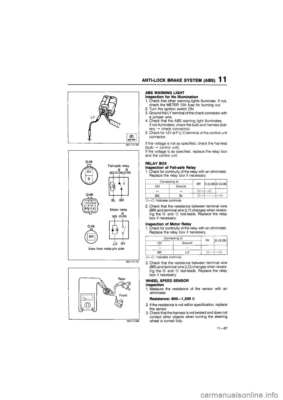
ABS WARNING LIGHT
Inspection for No Illumination
1. Check that other warning lights illuminate. If not,
check the METER 10A fuse for burning out.
2. Turn the ignition switch ON.
3. Ground the LY terminal
of
the check connector with
a jumper wire.
4. Check that the ABS warning light illuminates.
If not illuminated, check the bulb and harness (bat-
tery -» check connector).
5. Check for 12V at F (LY) terminal of the control unit
connector.
If the voltage is not as specified, check the harness
(bulb control unit).
If the voltage is as specified, replace the relay box
and the control unit.
RELAY BOX
Inspection of Fail-safe Relay
1. Check for continuity of the relay with an ohmmeter.
Replace the relay box if necessary.
Connecting to BR B (Q-08) B (Q-09) 12V Ground BR B (Q-08) B (Q-09)
— — O— —O
BG BL O— —O
O—O: Indicates continuity
2. Check that the resistance between terminal wire
(BR) and terminal wire (LY) changes when revers-
ing the © and © test-leads. Replace the relay
box if necessary.
Inspection of Motor Relay
1. Check for continuity of the relay with an ohmmeter.
Replace the relay box if necessary.
Connecting to RY B (Q-09) 12V Ground RY B (Q-09)
-—
BR LO o— O
O—O: Indicates continuity
2. Check that the resistance between terminal wire
(BR) and terminal wire (LO) changes when revers-
ing the © and © test-leads. Replace the relay
box if necessary.
WHEEL SPEED SENSOR
Inspection
1. Measure the resistance of the sensor with an
ohmmeter.
Resistance: 800—1,200 0
2. If the resistance is not within specification, replace
the sensor.
3. Check that the harness is not twisted and does not
contact other objects when turning the steering
wheel is turned fully.
11-87
Page 1677 of 1865

15 METER
METER
STRUCTURAL VIEW
DIGITAL ELECTRONIC DISPLAY METER
ANALOG DISPLAY METER
76G15X-007
1. Speedometer 5. Warning and indicator lights
2. Tachometer 6. Tripmeter
3. Water temperature gauge 7. Twin tripmeter change switch
4. Fuel gauge 8. Fuel garge scale change switch
15—22
Page 1692 of 1865

WARNING LIGHT AND SENDER 1 5
76G15X-090
Seat Belt Warning Light
76G15X-043
EC-AT Mode Indicator Light
POWER and ECONO indicator lights
do
not
il-
luminate.
NG
Check the hold switch. Refer
to
page 7B—63
NG
Replace the switch.
OK
NG
Check the mode switch. Refer
to
page 7B—63
NG
Replace the switch.
fOK
Replace the bulb
or
repair the harness (Meter
to
mode switch, EC-AT switch
to
control unit).
76G15X-091
76G15X-044
15—37
Page 1693 of 1865

1 5 WARNING AND SENDER
Shift Indicator Light
All shift indicator lights do not Illuminate when ignition switch on. (other warning light are all right.)
Check the voltage
at BY
terminal
of
the inhibitor switch connector with ignition switch
on.
Terminal Voltage
BY 12V
NG
Repair the harness (Fuse box
to
inhibitor switch).
OK
Check the inhibitor switch. Refer
to
page 7B—65
NG
Replace the inhibitor switch. Check the inhibitor switch. Refer
to
page 7B—65 Replace the inhibitor switch.
OK
NG
Check the bulbs
of
the shift indicator lights.
NG
Replace the bulb.
OK
Turn the ignition switch on, and check the voltage
at
each terminal
of
the meter connector with each con-dition.
Terminal Selector lever Voltage
YL (2J) P 12V
RG (1L) R 12V
YR (2L) N 12V
Y(1V) D 12V
YB (1S) 2 12V
YW (1M) 1 12V
NG
Repair the harness (Inhibitor switch
to
meter).
76G15X-087
O/D OFF Indicator Light
OK
Repair the harness (O/D OFF switch
to
ground).
76G15X092
15-38
Page 1698 of 1865

CENTRAL PROCESSING UNIT (CPU) 1 5
REMOVAL AND INSTALLATION
1. Disconnect the negative battery cable.
2. Disconnect the CPU connectors.
3. Release the lock and remove the CPU from the
joint box.
4. Install in the reverse order of removal.
ON-VEHICLE INSPECTION
Note: Check the voltage between "a through
I" terminal and ground.
Check the continuity between "m,
n" terminal and ground.
86U15X-075
Terminal Connecting
to
Measurement condition Measurement value
a Interior light and courtesy lights Any time Approx.
12V
b Batterv Anv time Approx.
12V
c No used
— —
d Ground Anv time OV
e Seat belt warning light Ignition switch
ON
Approx.
12V
f Enaine control unit Enaine runnina Approx.
12V
g Key cylinder illumination light Any time Approx.
12V
i Key reminder switch Insert the key into the cylinder
Pull out the key from the cylinder
Approx.
12V
OV
j Ignition switch (ON) Ignition switch
ON
Ignition switch OFF
or
ACC
Approx.
12V
OV
k Ignition switch (ACC) Ignition switch
ON or
ACC
Ignition switch OFF
Approx.
12V
OV
I Light switch (In the combination switch) Turn the light switch ACC and
ON
Light switch OFF
Approx.
12V
OV
m Seat belt switch Seat belt fastened
Seat belt unfastered
OQ
OO
n Door switch Door closed
Door open
OO
on
76G15X-009
15—43
Page 1854 of 1865

30 TECHNICAL DATA
Body type Specification (W) (BULB TRADE NO)
Item MX-6/Coupe Sedan Hatchback
Brake 1.4
Oil pressure 1.4
Fuel 1.4
Washer level 1.4
Rear 1.4
4WS
— —
1.4 (ECE)
Indicator and warning lights
Door 1.4 Indicator and warning lights Seat belt 1.4 Indicator and warning lights ABS 1.4
Alternator 1.4
High beam 3.4
Turn signal 3.4
O/D OFF 0.8
A/T mode 0.8 (ECE)
A/T position 0.8
Glove compartment light 3.4
Interior lights Interior light 10
Luggage compartment light 5
Motor 4.8
Hazard switch 1.4
Cigar lighter 3.4
Auto cruise main switch 0.5
Illumination lights AAS switch 1.4
Rear defroster switch 1.4
A/T switch 1.4
A/T 3.4
IG switch 1.4
STANDARD BOLT AND NUT TIGHTENING TORQUE
Diameter
mm (in)
Pitch
mm (in)
4T 6T 8T Diameter
mm (in)
Pitch
mm (in) N-m m-kg ft-lb N-m m-kg ft-lb N-m m-kg ft-lb
6 (0.236) 1 (0.039) 4.2-6.2 0.43-0.63 3.1-4.6 6.9-9.8 0.7-1.0 5.0-7.2 7.8-11.8 0.8-1.2 5.8—8.8
8 (0.315) 1.25 (0.049) 9.8—14.7 1.0-1.5 7.2-10.8 16-23 1.6-2.3 12-17 18—26 1.8-2.7 13-20
10 (0.394) 1.25 (0.049) 20-28 2.0—2.9 14-21 31-46 3.2-4.1 23—34 36-54 3.7-5.5 27-40
12 (0.472) 1.5 (0.059) 34—50 3.5-5.1 25-37 55-80 5,6-8.2 41-59 63-93 6.4-9.5 46-69
14 (0.551) 1.5 (0.059)
— — —
75-103 7.7-10.5 56-76 102—137 10-14 75-101
16 (0.630) 1.5 (0.059)
— — —
116-157 12-16 85-116 156-211 16-22 115-156
18 (0.709) 1.5 (0.059)
— — —
167-225 17-23 123-166 221-299 23-31 163—221
20 (0.787) 1.5 (0.059)
— — —
231-314 24-32 171-231 308—417 31-43 227-307
22 (0.866) 1.5 (0.059)
— — —
314—423 32-43 231-312 417—564 43-58 307-416
24 (0.945) 1.5 (0.059)
— — —
475—546 41—56 298—403 536-726 55-74 396-536
30—40