wheel MAZDA MIATA 1991 Factory Owner's Guide
[x] Cancel search | Manufacturer: MAZDA, Model Year: 1991, Model line: MIATA, Model: MAZDA MIATA 1991Pages: 392, PDF Size: 29.45 MB
Page 213 of 392

procedure.
Fig. 5: Exploded View of Front Disc Brake Assembly (Protege & 323)
Courtesy of MAZDA MOTORS CORP.
Removal (Navajo)
1. To prevent master cylinder overflow when caliper piston is depressed, remove and discard some brake
fluid from master cylinder. Raise vehicle, and support using safety stands.
2. Remove front wheel assembly. Place a large "C" clamp on caliper. See Fig. 9
. Tighten clamp to bottom
piston in cylinder bore. Remove clamp.
3. Remove dirt around caliper pin tabs. Tap upper caliper pin toward inboard side of vehicle until pin tabs
1991 Mazda MX-5 Miata
BRAKE SYSTEM 1991 BRAKES Mazda Brake System
Microsoft
Sunday, July 05, 2009 2:18:08 PMPage 10 © 2005 Mitchell Repair Information Company, LLC.
Page 214 of 392
touch spindle face.
4. Insert screwdriver into slot provided behind pin tabs on inboard side of pin. Using pliers, compress end of
pin while using screwdriver to pry until tabs slip into spindle groove.
5. Place a 7/16" diameter punch on end of pin, and drive caliper pin out of caliper slide groove. Repeat
procedure for lower pin. Remove caliper from rotor. Remove outer brake pad. Compress anti-rattle spring
clip, and remove inner brake pad. Support caliper aside. Replace pad if lining thickness is less than
specified. See MINIMUM PAD LINING SPECIFICATIONS (FRONT) TABLE.
Installation
Use "C" clamp to push caliper piston into piston bore until it bottoms out. To install, reverse removal procedure.
Bleed air from brake system.
Removal & Installation (RX7 With 4-Piston Caliper)
Raise and support front of vehicle. Remove wheels. Remove pad pins and pad springs. See Fig. 6 . Remove
brake pads and shims. Replace pad if lining thickness is less than specified. See MINIMUM PAD LINING
SPECIFICATIONS (FRONT) . To install, reverse removal procedure. CAUTION: During installation, DO NOT tap caliper pin too far into spindle groove. If
this happens, tap pin in other direction until tabs snap back into place.
Tabs on each end of caliper pin must be free to catch on spindle flanks.
1991 Mazda MX-5 Miata
BRAKE SYSTEM 1991 BRAKES Mazda Brake System
Microsoft
Sunday, July 05, 2009 2:18:08 PMPage 11 © 2005 Mitchell Repair Information Company, LLC.
Page 215 of 392
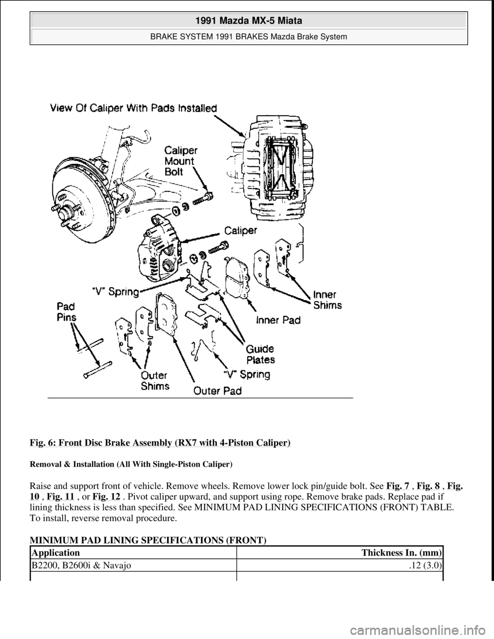
Fig. 6: Front Disc Brake Assembly (RX7 with 4-Piston Caliper)
Removal & Installation (All With Single-Piston Caliper)
Raise and support front of vehicle. Remove wheels. Remove lower lock pin/guide bolt. See Fig. 7 , Fig. 8 , Fig.
10 , Fig. 11 , or Fig. 12 . Pivot caliper upward, and support using rope. Remove brake pads. Replace pad if
lining thickness is less than specified. See MINIMUM PAD LINING SPECIFICATIONS (FRONT) TABLE.
To install, reverse removal procedure.
MINIMUM PAD LINING SPECIFICATIONS (FRONT)
ApplicationThickness In. (mm)
B2200, B2600i & Navajo.12 (3.0)
1991 Mazda MX-5 Miata
BRAKE SYSTEM 1991 BRAKES Mazda Brake System
Microsoft
Sunday, July 05, 2009 2:18:08 PMPage 12 © 2005 Mitchell Repair Information Company, LLC.
Page 221 of 392
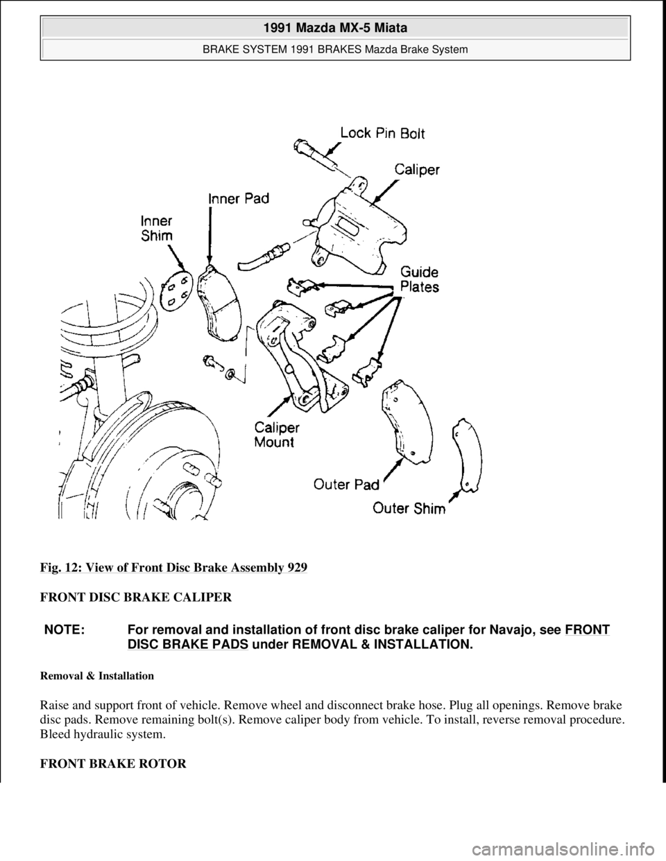
Fig. 12: View of Front Disc Brake Assembly 929
FRONT DISC BRAKE CALIPER
Removal & Installation
Raise and support front of vehicle. Remove wheel and disconnect brake hose. Plug all openings. Remove brake
disc pads. Remove remaining bolt(s). Remove caliper body from vehicle. To install, reverse removal procedure.
Bleed hydraulic system.
FRONT BRAKE ROTOR
NOTE: For removal and installation of front disc brake caliper for Navajo, see FRONT
DISC BRAKE PADS under REMOVAL & INSTALLATION.
1991 Mazda MX-5 Miata
BRAKE SYSTEM 1991 BRAKES Mazda Brake System
Microsoft
Sunday, July 05, 2009 2:18:08 PMPage 18 © 2005 Mitchell Repair Information Company, LLC.
Page 222 of 392
Removal & Installation (B2200 & B2600i 2WD)
1. With caliper assembly removed, remove wheel hub grease cap, cotter pin, lock plate and ring adjusting
lock nut. Remove thrust washer and outer bearing from hub. Slide hub and rotor assembly from spindle.
2. Mark rotor-to-hub position. Separate rotor from hub. Machine rotor if lateral runout exceeds
specification. Replace rotor if measured thickness is less than specified minimum thickness. See DISC
BRAKE SPECIFICATIONS at end of article.
3. To install, reverse removal procedure and evenly tighten rotor-to-hub bolts. Adjust wheel bearings.
Removal & Installation (B2600i 4WD) 1) Remove front caliper. Set hub to FREE position. Remove hub
bolts. Remove hub as an assembly. Install 2 bolts and nuts to retain hub assembly together. Remove snap
ring and spacer.
4. Remove set bolt and plate. Remove nut. Remove rotor and hub assembly. Mark rotor-to-hub position.
Remove rotor from hub. Machine rotor if lateral runout exceeds specification. Replace rotor if measured
thickness is less than specified minimum thickness. See DISC BRAKE SPECIFICATIONS
at end of
article. To install, reverse removal procedure.
Removal & Installation (Miata, MPV, MX-6, Protege, RX7, 323 & 626)
1. Raise and support front of vehicle. Remove wheel. Remove caliper with brake hose connected. Support
caliper using rope. Remove 2 rotor-to-hub screws. Remove rotor.
2. Machine rotor if lateral runout exceeds specification. Replace rotor if measured thickness is less than
specified minimum thickness. See DISC BRAKE SPECIFICATIONS
at end of article. To install,
reverse removal procedure.
Removal & Installation (Navajo 2WD)
1. Raise vehicle, and support using safety stands. Remove wheel and caliper assemblies. Remove dust cap,
cotter pin, nut, washer and outer bearing. Carefully remove hub and rotor assembly. Remove inner
bearing and seal.
2. To install, reverse removal procedure. Adjust front wheel bearings. While rotating rotor, tighten adjusting
nut to 17-25 ft. lbs. (23-34 N.m). Back off adjusting nut 120-180 degrees. Install bearing retainer and new
cotter pin.
Removal (Navajo 4WD With Automatic Locking Hubs)
1. Raise vehicle, and support using safety stands. Remove wheel assembly and caliper. See FRONT DISC
BRAKE PADS under REMOVAL & INSTALLATION. Remove retainer washers from lug nut studs.
Remove automatic locking hub housing from spindle.
2. Remove snap ring from end of spindle shaft. Remove axle spacer. See Fig. 13
. Carefully pull plastic
moving cam off wheel bearing adjusting nut. Remove 2 plastic thrust spacers from adjusting nut. Using a
magnet, remove locking key.
CAUTION: DO NOT pry on plastic cam or spacers during removal as damage
may result. To prevent damaging spindle threads, remove locking
key before removing adjusting nut.
1991 Mazda MX-5 Miata
BRAKE SYSTEM 1991 BRAKES Mazda Brake System
Microsoft
Sunday, July 05, 2009 2:18:08 PMPage 19 © 2005 Mitchell Repair Information Company, LLC.
Page 224 of 392
(T70T-4252-B), remove wheel bearing adjusting nut. Remove outer wheel bearing, and then remove
rotor.
Installation
When installing rotor, outer bearing and adjusting nut, tighten adjusting nut to 35 ft. lbs (47 N.m) to seat
bearings. Spin rotor, and back off adjusting nut 1/4 turn. Tighten adjusting nut to 16 INCH lbs. (1.8 N.m). To
install remaining components, reverse removal procedure. See Fig. 13
. After assembly is complete, wheel to
spindle end play should be .001-.003" (.02-.08 mm).
Removal (Navajo 4WD With Manual Locking Hubs)
1. Raise and support vehicle. Remove wheel assembly and caliper. See FRONT DISC BRAKE PADS
under REMOVAL & INSTALLATION. Remove retainer washers from lug nut studs. Remove manual
locking hub housing from spindle.
2. Remove snap ring from end of spindle shaft. Remove axle spacer. See Fig. 14
. Using Lock Nut Wrench
(T86T-1197-A), remove outer wheel bearing lock-nut. Remove lock washer. Using Lock Nut Wrench
(T86T-1197-A), remove inner wheel bearing lock nut, outer wheel bearing and rotor. CAUTION: Extreme caution must be used when aligning adjusting nut lug with
spindle locking key slot to prevent damage to locking key. Extreme
caution must be used when aligning fixed cam key with spindle key slot to
prevent damage to fixed cam.
1991 Mazda MX-5 Miata
BRAKE SYSTEM 1991 BRAKES Mazda Brake System
Microsoft
Sunday, July 05, 2009 2:18:08 PMPage 21 © 2005 Mitchell Repair Information Company, LLC.
Page 226 of 392

install remaining components, reverse removal procedure. See Fig. 14. After assembly is complete, wheel to
spindle end play should be .001-.003" (.02-.08 mm).
Removal & Installation (929)
1. Raise and support front of vehicle. Remove wheel. Remove caliper with brake hose connected. Support
caliper with rope. Remove hub cap, wheel bearing lock nut and washer. Remove hub and rotor assembly.
2. Machine rotor if lateral runout exceeds specification. Replace rotor if measured thickness is less than
specified minimum thickness. See DISC BRAKE SPECIFICATIONS
at end of article.
3. To install, reverse removal procedure. Replace wheel bearing lock nut, and tighten to 72-130 ft. lbs. (98-
177 N.m). Check hub end play. If end play exceeds .002" (.05 mm), replace bearing. If end play is within
specification, stake lock nut at groove in axle shaft.
REAR DISC BRAKE PADS
Removal & Installation (Miata, Protege & 323)
1. Raise and support rear of vehicle. Remove wheel. Remove manual adjustment gear concealment plug
from caliper. See Fig. 15
. Insert an appropriate size Allen wrench through hole and turn manual
ad
justment gear counterclockwise to retract caliper piston.
1991 Mazda MX-5 Miata
BRAKE SYSTEM 1991 BRAKES Mazda Brake System
Microsoft
Sunday, July 05, 2009 2:18:08 PMPage 23 © 2005 Mitchell Repair Information Company, LLC.
Page 227 of 392
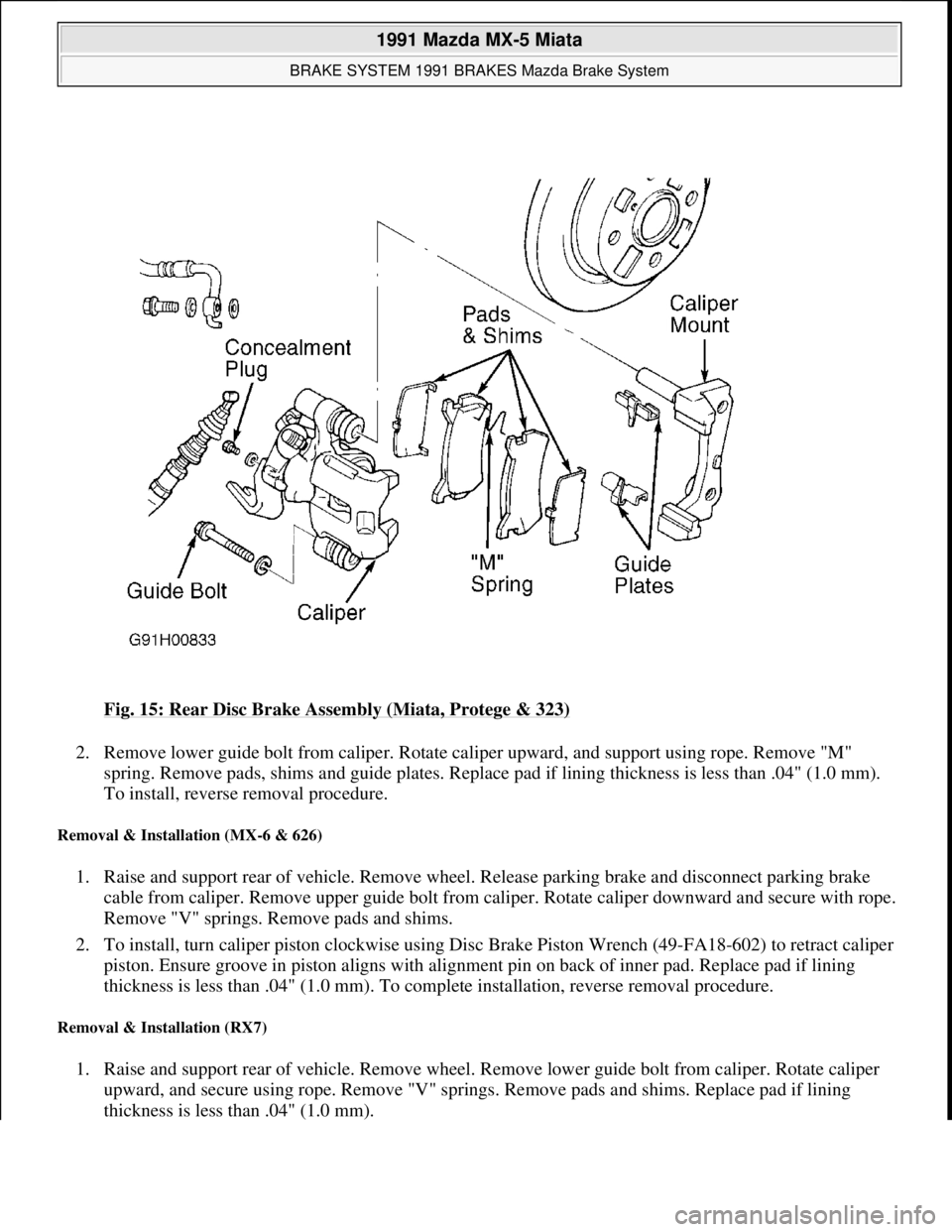
Fig. 15: Rear Disc Brake Assembly (Miata, Protege & 323)
2. Remove lower guide bolt from caliper. Rotate caliper upward, and support using rope. Remove "M"
spring. Remove pads, shims and guide plates. Replace pad if lining thickness is less than .04" (1.0 mm).
To install, reverse removal procedure.
Removal & Installation (MX-6 & 626)
1. Raise and support rear of vehicle. Remove wheel. Release parking brake and disconnect parking brake
cable from caliper. Remove upper guide bolt from caliper. Rotate caliper downward and secure with rope.
Remove "V" springs. Remove pads and shims.
2. To install, turn caliper piston clockwise using Disc Brake Piston Wrench (49-FA18-602) to retract caliper
piston. Ensure groove in piston aligns with alignment pin on back of inner pad. Replace pad if lining
thickness is less than .04" (1.0 mm). To complete installation, reverse removal procedure.
Removal & Installation (RX7)
1. Raise and support rear of vehicle. Remove wheel. Remove lower guide bolt from caliper. Rotate caliper
upward, and secure using rope. Remove "V" springs. Remove pads and shims. Replace pad if lining
thickness is less than .04" (1.0 mm).
1991 Mazda MX-5 Miata
BRAKE SYSTEM 1991 BRAKES Mazda Brake System
Microsoft
Sunday, July 05, 2009 2:18:08 PMPage 24 © 2005 Mitchell Repair Information Company, LLC.
Page 228 of 392
2. To install, turn caliper piston clockwise using Disc Brake Piston Wrench (49-FA18-602) to retract caliper
piston. Ensure groove in piston aligns with alignment pin on back of inner pad. To install remaining
components, reverse removal procedure.
Removal & Installation (929)
Raise and support rear of vehicle. Remove wheel. Remove lower guide bolt from caliper. Rotate caliper upward
and secure with rope. Remove pads and shims. Replace pad if lining thickness is less than .08" (2.0 mm). To
install, reverse removal procedure.
REAR BRAKE CALIPER
Removal & Installation
1. Raise and support rear of vehicle. On all models except 929, release parking brake and disconnect parking
brake cable from caliper. On all models, disconnect brake hose from caliper.
2. On Miata, Protege and 323, remove manual adjustment gear concealment plug from caliper. See Fig. 15
.
Insert an appropriate size Allen wrench through hole and turn manual adjustment gear counterclockwise
to retract caliper piston.
3. On all models, remove lower guide bolt from caliper. Rotate caliper upward. Pull caliper toward center of
vehicle to slide it off of caliper mount. To install, reverse removal procedure. Bleed hydraulic system.
REAR BRAKE ROTOR
Removal & Installation (Miata, Protege, RX7, 323 & 929)
Remove rear brake caliper. Remove rotor-to-hub screws. Remove rotor. Machine rotor if lateral runout exceeds
specification. Replace rotor if measured thickness is less than specified minimum thickness. See DISC BRAKE
SPECIFICATIONS at end of article. To install, reverse removal procedure.
Removal & Installation (MX-6 & 626)
1. Remove rear caliper, and wire aside. Remove grease cap. Remove lock nut. Remove rotor. Machine rotor
if lateral runout exceeds specification. Replace rotor if measured thickness is less than specified minimum
thickness. See DISC BRAKE SPECIFICATIONS
at end of article.
2. To install, reverse removal procedure. Tighten lock nut to 73-131 ft. lbs. (99-178 N.m). Check end play at
grease cap. If end play exceeds .008" (.20 mm), replace wheel bearings.
REAR BRAKE SHOES
Removal (B2200, B2600i & MPV)
With brake drum removed, remove brake shoe return springs, retaining springs and guide pins. See Fig. 16 or
Fig. 17
. Remove brake shoes. Remove parking brake strut, and disconnect parking brake cable from operating
lever of secondar
y shoe. Minimum lining thickness is .04" (1 mm).
1991 Mazda MX-5 Miata
BRAKE SYSTEM 1991 BRAKES Mazda Brake System
Microsoft
Sunday, July 05, 2009 2:18:08 PMPage 25 © 2005 Mitchell Repair Information Company, LLC.
Page 231 of 392

Fig. 18: View of Rear Drum Brake Assembly (Typical)
Courtesy of MAZDA MOTORS CORP.
Installation
1. Apply brake grease to brake shoe contact areas on backing plate. When installing adjuster between shoes,
insert a flat-tipped screwdriver between adjuster quadrant and meshing teeth on MX-6 and 626, or
between quadrant and knurled pin on Protege and 323. See Fig. 2
.
2. To fully retract adjuster, move quadrant until it touches backing plate. To complete installation, reverse
removal procedure. Adjust wheel bearings and stake lock nut.
Removal (Navajo)
1. Remove wheel assembly and drum. Place a wheel cylinder clamp over ends of wheel cylinder. Disengage
ad
justing lever from adjusting screw by pulling backwards on lever cable. See Fig. 19 .
1991 Mazda MX-5 Miata
BRAKE SYSTEM 1991 BRAKES Mazda Brake System
Microsoft
Sunday, July 05, 2009 2:18:08 PMPage 28 © 2005 Mitchell Repair Information Company, LLC.