wheel MAZDA MIATA 1991 Factory Owner's Manual
[x] Cancel search | Manufacturer: MAZDA, Model Year: 1991, Model line: MIATA, Model: MAZDA MIATA 1991Pages: 392, PDF Size: 29.45 MB
Page 190 of 392
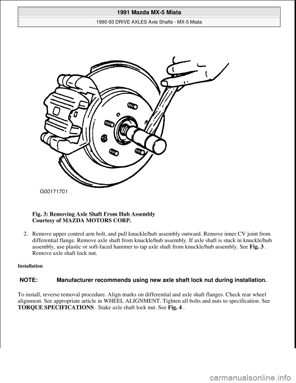
Fig. 3: Removing Axle Shaft From Hub Assembly
Courtesy of MAZDA MOTORS CORP.
2. Remove upper control arm bolt, and pull knuckle/hub assembly outward. Remove inner CV joint from
differential flange. Remove axle shaft from knuckle/hub assembly. If axle shaft is stuck in knuckle/hub
assembly, use plastic or soft-faced hammer to tap axle shaft from knuckle/hub assembly. See Fig. 3
.
Remove axle shaft lock nut.
Installation
To install, reverse removal procedure. Align marks on differential and axle shaft flanges. Check rear wheel
alignment. See appropriate article in WHEEL ALIGNMENT. Tighten all bolts and nuts to specification. See
TORQUE SPECIFICATIONS
. Stake axle shaft lock nut. See Fig. 4.
NOTE: Manufacturer recommends using new axle shaft lock nut during installation.
1991 Mazda MX-5 Miata
1990-93 DRIVE AXLES Axle Shafts - MX-5 Miata
Microsoft
Sunday, July 05, 2009 2:16:33 PMPage 4 © 2005 Mitchell Repair Information Company, LLC.
Page 200 of 392
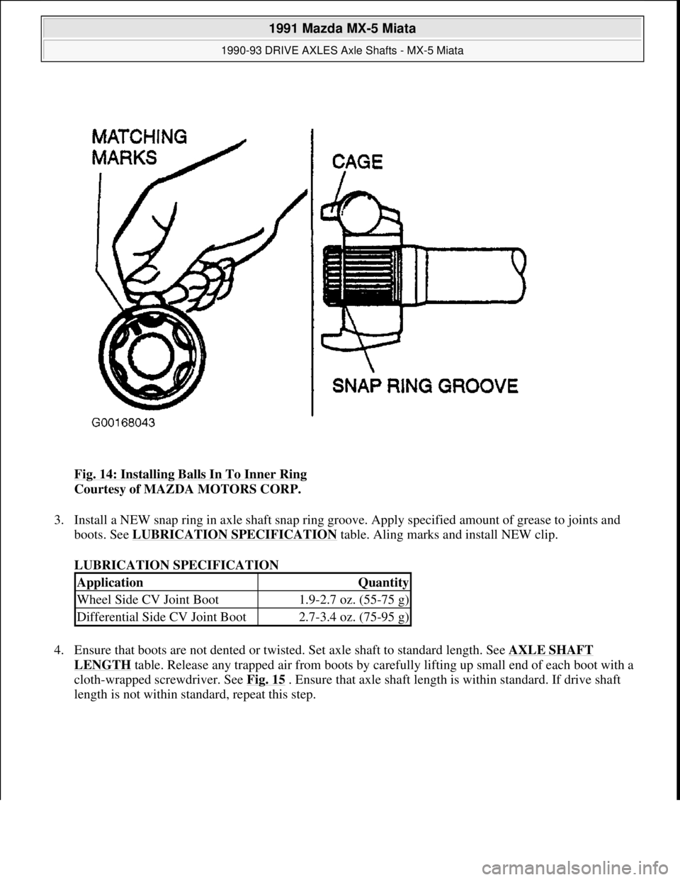
Fig. 14: Installing Balls In To Inner Ring
Courtesy of MAZDA MOTORS CORP.
3. Install a NEW snap ring in axle shaft snap ring groove. Apply specified amount of grease to joints and
boots. See LUBRICATION SPECIFICATION
table. Aling marks and install NEW clip.
LUBRICATION SPECIFICATION
4. Ensure that boots are not dented or twisted. Set axle shaft to standard length. See AXLE SHAFT
LENGTH table. Release any trapped air from boots by carefully lifting up small end of each boot with a
cloth-wrapped screwdriver. See Fig. 15
. Ensure that axle shaft length is within standard. If drive shaft
length is not within standard, repeat this step.
ApplicationQuantity
Wheel Side CV Joint Boot1.9-2.7 oz. (55-75 g)
Differential Side CV Joint Boot2.7-3.4 oz. (75-95 g)
1991 Mazda MX-5 Miata
1990-93 DRIVE AXLES Axle Shafts - MX-5 Miata
Microsoft
Sunday, July 05, 2009 2:16:33 PMPage 14 © 2005 Mitchell Repair Information Company, LLC.
Page 202 of 392
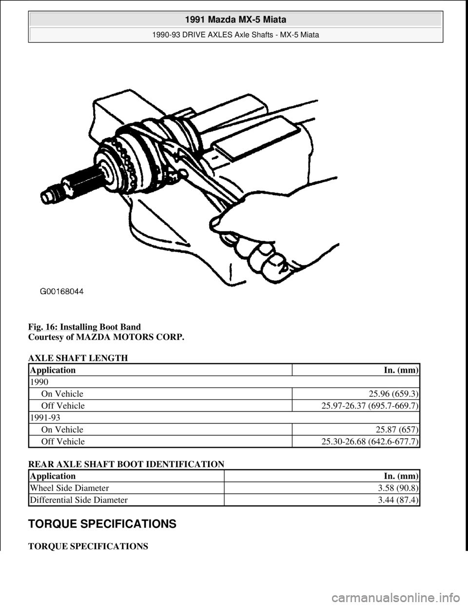
Fig. 16: Installing Boot Band
Courtesy of MAZDA MOTORS CORP.
AXLE SHAFT LENGTH
REAR AXLE SHAFT BOOT IDENTIFICATION
TORQUE SPECIFICATIONS
TORQUE SPECIFICATIONS
ApplicationIn. (mm)
1990
On Vehicle25.96 (659.3)
Off Vehicle25.97-26.37 (695.7-669.7)
1991-93
On Vehicle25.87 (657)
Off Vehicle25.30-26.68 (642.6-677.7)
ApplicationIn. (mm)
Wheel Side Diameter3.58 (90.8)
Differential Side Diameter3.44 (87.4)
1991 Mazda MX-5 Miata
1990-93 DRIVE AXLES Axle Shafts - MX-5 Miata
Microsoft
Sunday, July 05, 2009 2:16:33 PMPage 16 © 2005 Mitchell Repair Information Company, LLC.
Page 203 of 392
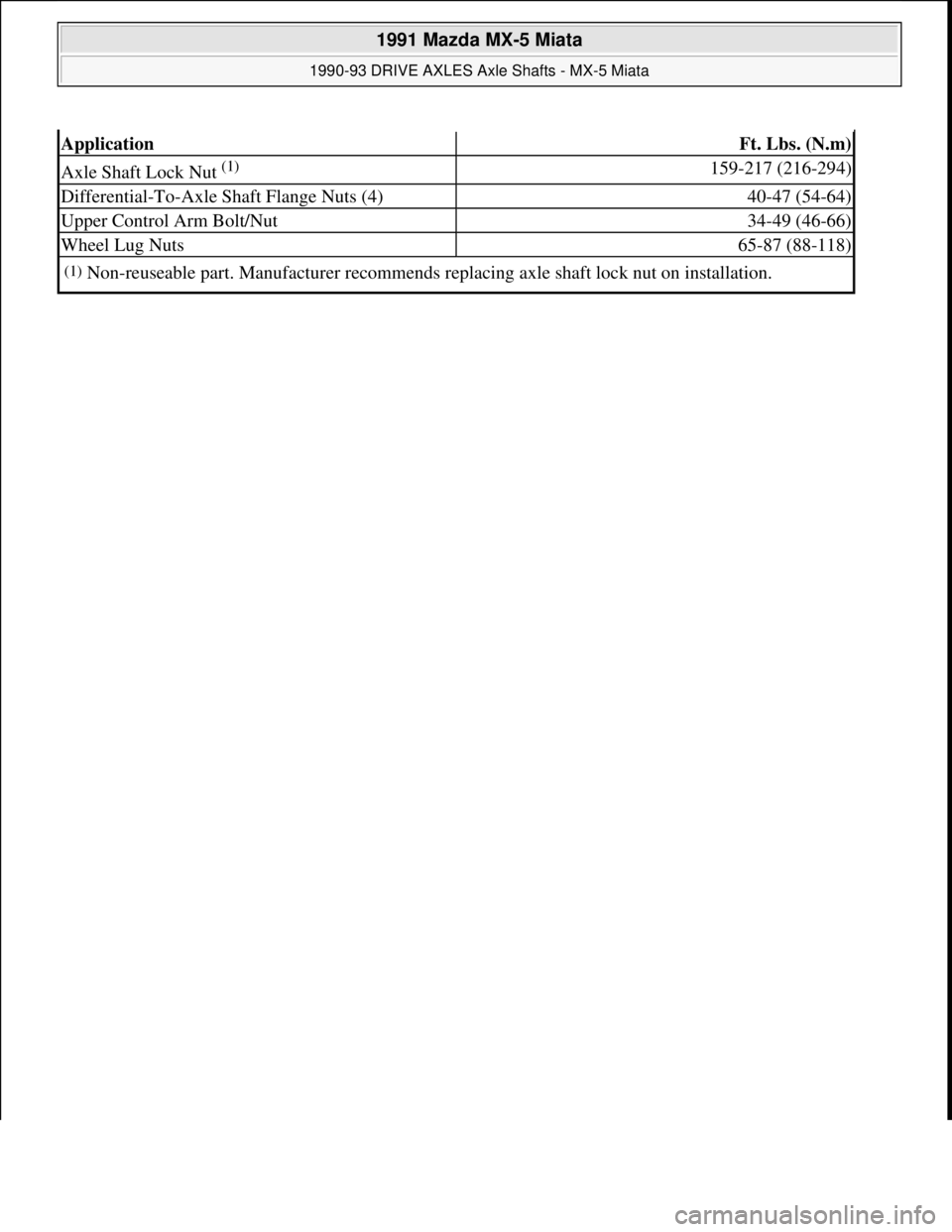
ApplicationFt. Lbs. (N.m)
Axle Shaft Lock Nut (1) 159-217 (216-294)
Differential-To-Axle Shaft Flange Nuts (4)40-47 (54-64)
Upper Control Arm Bolt/Nut34-49 (46-66)
Wheel Lug Nuts65-87 (88-118)
(1)Non-reuseable part. Manufacturer recommends replacing axle shaft lock nut on installation.
1991 Mazda MX-5 Miata
1990-93 DRIVE AXLES Axle Shafts - MX-5 Miata
Microsoft
Sunday, July 05, 2009 2:16:33 PMPage 17 © 2005 Mitchell Repair Information Company, LLC.
Page 206 of 392
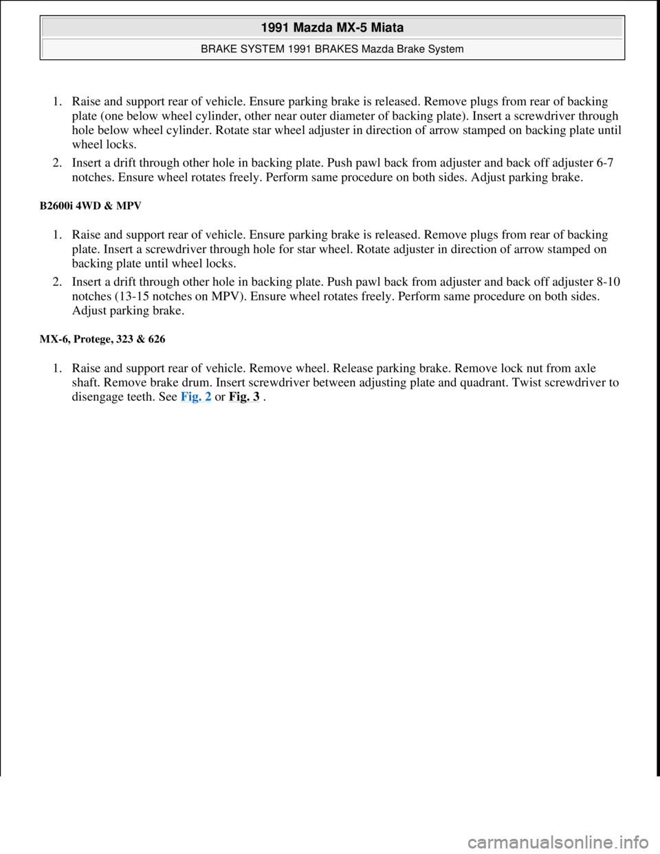
1. Raise and support rear of vehicle. Ensure parking brake is released. Remove plugs from rear of backing
plate (one below wheel cylinder, other near outer diameter of backing plate). Insert a screwdriver through
hole below wheel cylinder. Rotate star wheel adjuster in direction of arrow stamped on backing plate until
wheel locks.
2. Insert a drift through other hole in backing plate. Push pawl back from adjuster and back off adjuster 6-7
notches. Ensure wheel rotates freely. Perform same procedure on both sides. Adjust parking brake.
B2600i 4WD & MPV
1. Raise and support rear of vehicle. Ensure parking brake is released. Remove plugs from rear of backing
plate. Insert a screwdriver through hole for star wheel. Rotate adjuster in direction of arrow stamped on
backing plate until wheel locks.
2. Insert a drift through other hole in backing plate. Push pawl back from adjuster and back off adjuster 8-10
notches (13-15 notches on MPV). Ensure wheel rotates freely. Perform same procedure on both sides.
Adjust parking brake.
MX-6, Protege, 323 & 626
1. Raise and support rear of vehicle. Remove wheel. Release parking brake. Remove lock nut from axle
shaft. Remove brake drum. Insert screwdriver between adjusting plate and quadrant. Twist screwdriver to
disen
gage teeth. See Fig. 2 or Fig. 3 .
1991 Mazda MX-5 Miata
BRAKE SYSTEM 1991 BRAKES Mazda Brake System
Microsoft
Sunday, July 05, 2009 2:18:08 PMPage 3 © 2005 Mitchell Repair Information Company, LLC.
Page 208 of 392
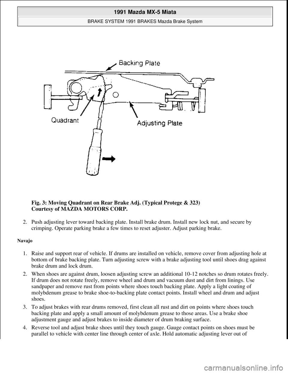
Fig. 3: Moving Quadrant on Rear Brake Adj. (Typical Protege & 323)
Courtesy of MAZDA MOTORS CORP.
2. Push adjusting lever toward backing plate. Install brake drum. Install new lock nut, and secure by
crimping. Operate parking brake a few times to reset adjuster. Adjust parking brake.
Navajo
1. Raise and support rear of vehicle. If drums are installed on vehicle, remove cover from adjusting hole at
bottom of brake backing plate. Turn adjusting screw with a brake adjusting tool until shoes drag against
brake drum and lock drum.
2. When shoes are against drum, loosen adjusting screw an additional 10-12 notches so drum rotates freely.
If drum does not rotate freely, remove wheel and drum and vacuum dust and dirt from linings. Use
sandpaper and remove rust from points where shoes touch backing plate. Apply a light coating of
molybdenum grease to brake shoe-to-backing plate contact points. Install wheel and drum and adjust
shoes.
3. To adjust brakes with rear drums removed, first clean all rust and dirt on points where shoes touch
backing plate and apply a small amount of molybdenum grease to those areas. Use a brake shoe
adjustment gauge and adjust brakes to inside diameter of drum braking surface.
4. Reverse tool and adjust brake shoes until they touch gauge. Gauge contact points on shoes must be
parallel to vehicle with center line throu
gh center of axle. Hold automatic adjusting lever out of
1991 Mazda MX-5 Miata
BRAKE SYSTEM 1991 BRAKES Mazda Brake System
Microsoft
Sunday, July 05, 2009 2:18:08 PMPage 5 © 2005 Mitchell Repair Information Company, LLC.
Page 209 of 392

engagement while rotating adjusting screw to prevent burring screw slots. Ensure adjusting screw rotates
freely.
PARKING BRAKE
B2200 & B2600i
1. Depress brake pedal several times while vehicle is moving in Reverse. Ensure brakes are properly
adjusted. Pull parking brake lever with a force of 44 lbs. (20 kg). If stroke is 7-12 notches, parking brake
is properly adjusted.
2. If stroke is not 7-12 notches, raise and support rear of vehicle. Release parking brake lever. Loosen cable
lock nut at lever end of cable. Rotate adjusting nut until correct stroke is obtained. Operate parking brake
several times and ensure rear wheels rotate freely. Ensure parking brake warning light illuminates when
brake lever is pulled one notch.
Navajo
1. Adjust service brakes before adjusting parking brake cable. Ensure brake drums are cold. Apply parking
brake to fully depressed position. Grip threaded rod to prevent it from spinning.
2. Thread equalizer nut 6 full turns past its original position on threaded rod. See Fig. 4
. Check cable
tension at rear of equalizer assembly using Cable Tension Gauge (021-00018). If tension is not 400-600
lbs. (182-272 k
g), repeat step 2).
1991 Mazda MX-5 Miata
BRAKE SYSTEM 1991 BRAKES Mazda Brake System
Microsoft
Sunday, July 05, 2009 2:18:08 PMPage 6 © 2005 Mitchell Repair Information Company, LLC.
Page 210 of 392

Fig. 4: Adjusting Parking Brake (Navajo)
Courtesy of FORD MOTOR CO.
3. Release pedal, and check rear wheel drag. If drag is noted, remove drums, and check for clearance
between parking brake lever and cam plate. Cables should be tight enough to allow full application of rear
brakes and loose enough to allow full release of rear brakes.
929
1. Depress brake pedal several times. Pull parking brake lever with a force of 44 lbs. (20 kg). If stroke is 6-8
notches, parking brake is properly adjusted. If stroke is not 6-8 notches, adjust parking brake shoes. See
PARKING BRAKE SHOES under ADJUSTMENTS
.
NOTE: Tension limiter will reset parking brake tension any time system is
disconnected if distance between bracket and cinch strap hook is reduced
during adjustment. When adjustment has been performed so cinch strap
contacts bracket, system tension will increase greatly. This may cause an over-
tension condition. When available adjustment travel has been used, replace
tension limiter.
NOTE: If rear brake shoes are removed for any reason, parking brake cable
1991 Mazda MX-5 Miata
BRAKE SYSTEM 1991 BRAKES Mazda Brake System
Microsoft
Sunday, July 05, 2009 2:18:08 PMPage 7 © 2005 Mitchell Repair Information Company, LLC.
Page 211 of 392
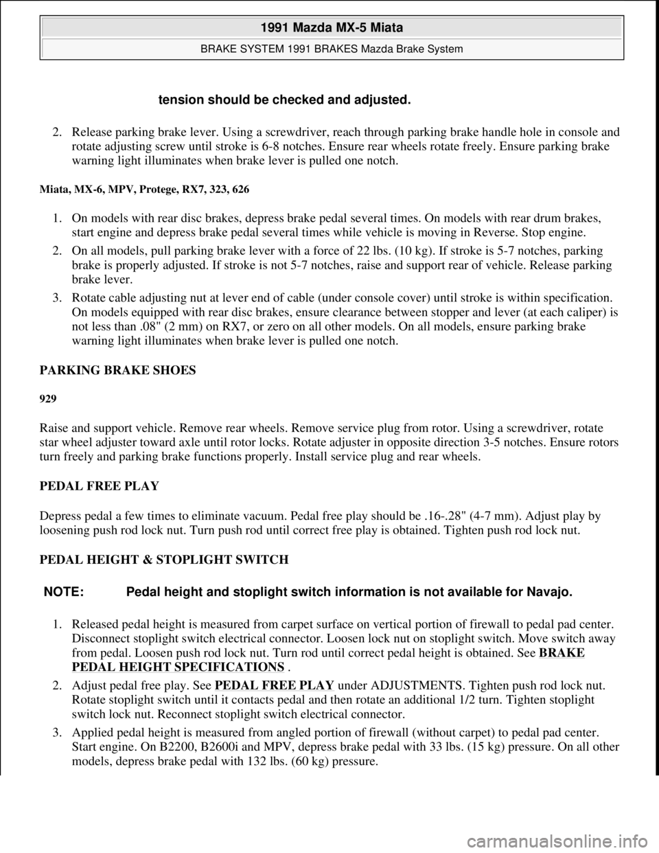
2. Release parking brake lever. Using a screwdriver, reach through parking brake handle hole in console and
rotate adjusting screw until stroke is 6-8 notches. Ensure rear wheels rotate freely. Ensure parking brake
warning light illuminates when brake lever is pulled one notch.
Miata, MX-6, MPV, Protege, RX7, 323, 626
1. On models with rear disc brakes, depress brake pedal several times. On models with rear drum brakes,
start engine and depress brake pedal several times while vehicle is moving in Reverse. Stop engine.
2. On all models, pull parking brake lever with a force of 22 lbs. (10 kg). If stroke is 5-7 notches, parking
brake is properly adjusted. If stroke is not 5-7 notches, raise and support rear of vehicle. Release parking
brake lever.
3. Rotate cable adjusting nut at lever end of cable (under console cover) until stroke is within specification.
On models equipped with rear disc brakes, ensure clearance between stopper and lever (at each caliper) is
not less than .08" (2 mm) on RX7, or zero on all other models. On all models, ensure parking brake
warning light illuminates when brake lever is pulled one notch.
PARKING BRAKE SHOES
929
Raise and support vehicle. Remove rear wheels. Remove service plug from rotor. Using a screwdriver, rotate
star wheel adjuster toward axle until rotor locks. Rotate adjuster in opposite direction 3-5 notches. Ensure rotors
turn freely and parking brake functions properly. Install service plug and rear wheels.
PEDAL FREE PLAY
Depress pedal a few times to eliminate vacuum. Pedal free play should be .16-.28" (4-7 mm). Adjust play by
loosening push rod lock nut. Turn push rod until correct free play is obtained. Tighten push rod lock nut.
PEDAL HEIGHT & STOPLIGHT SWITCH
1. Released pedal height is measured from carpet surface on vertical portion of firewall to pedal pad center.
Disconnect stoplight switch electrical connector. Loosen lock nut on stoplight switch. Move switch away
from pedal. Loosen push rod lock nut. Turn rod until correct pedal height is obtained. See BRAKE
PEDAL HEIGHT SPECIFICATIONS .
2. Adjust pedal free play. See PEDAL FREE PLAY
under ADJUSTMENTS. Tighten push rod lock nut.
Rotate stoplight switch until it contacts pedal and then rotate an additional 1/2 turn. Tighten stoplight
switch lock nut. Reconnect stoplight switch electrical connector.
3. Applied pedal height is measured from angled portion of firewall (without carpet) to pedal pad center.
Start engine. On B2200, B2600i and MPV, depress brake pedal with 33 lbs. (15 kg) pressure. On all other
models, depress brake pedal with 132 lbs. (60 k
g) pressure. tension should be checked and adjusted.
NOTE: Pedal height and stoplight switch information is not available for Navajo.
1991 Mazda MX-5 Miata
BRAKE SYSTEM 1991 BRAKES Mazda Brake System
Microsoft
Sunday, July 05, 2009 2:18:08 PMPage 8 © 2005 Mitchell Repair Information Company, LLC.
Page 212 of 392
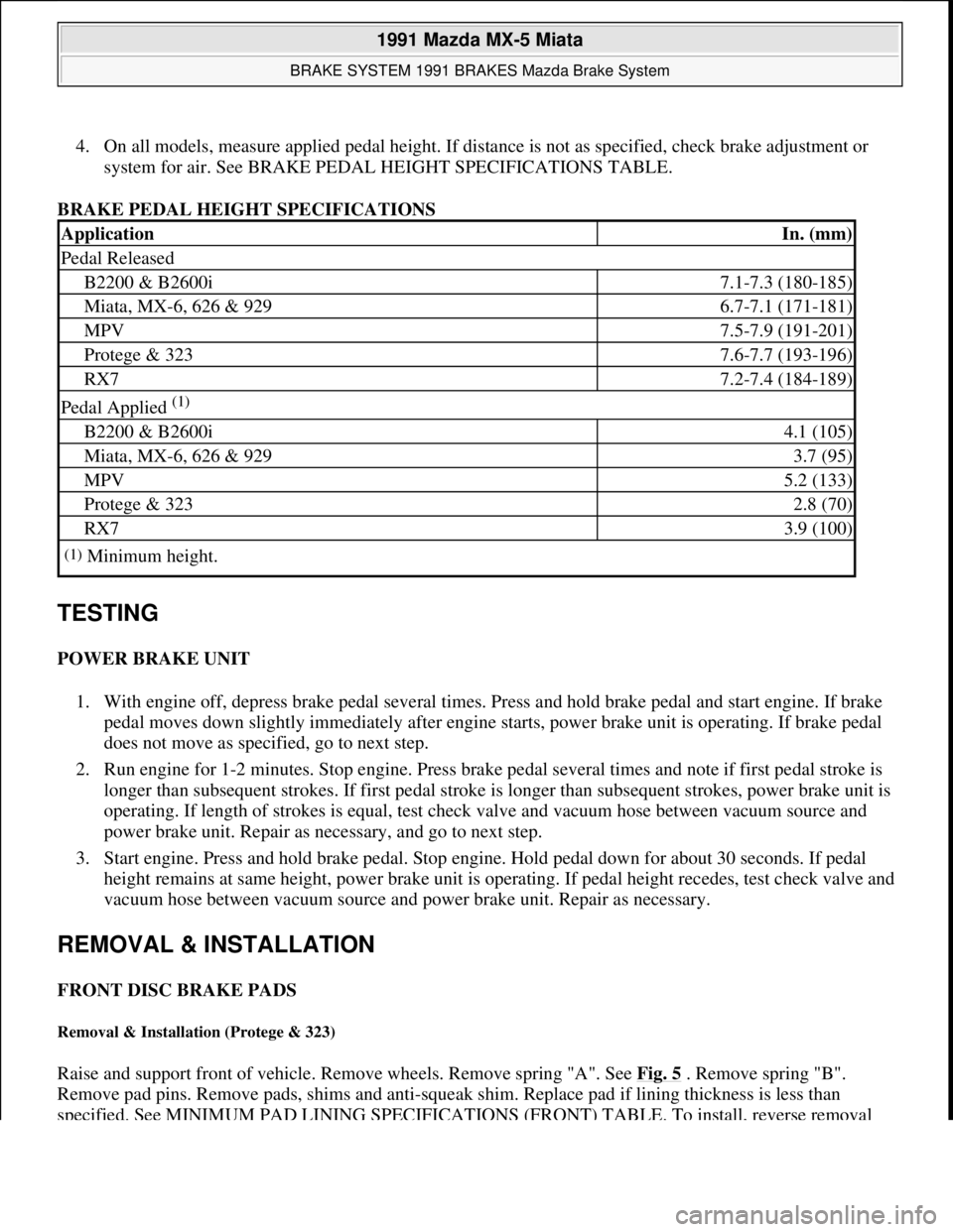
4. On all models, measure applied pedal height. If distance is not as specified, check brake adjustment or
system for air. See BRAKE PEDAL HEIGHT SPECIFICATIONS TABLE.
BRAKE PEDAL HEIGHT SPECIFICATIONS
TESTING
POWER BRAKE UNIT
1. With engine off, depress brake pedal several times. Press and hold brake pedal and start engine. If brake
pedal moves down slightly immediately after engine starts, power brake unit is operating. If brake pedal
does not move as specified, go to next step.
2. Run engine for 1-2 minutes. Stop engine. Press brake pedal several times and note if first pedal stroke is
longer than subsequent strokes. If first pedal stroke is longer than subsequent strokes, power brake unit is
operating. If length of strokes is equal, test check valve and vacuum hose between vacuum source and
power brake unit. Repair as necessary, and go to next step.
3. Start engine. Press and hold brake pedal. Stop engine. Hold pedal down for about 30 seconds. If pedal
height remains at same height, power brake unit is operating. If pedal height recedes, test check valve and
vacuum hose between vacuum source and power brake unit. Repair as necessary.
REMOVAL & INSTALLATION
FRONT DISC BRAKE PADS
Removal & Installation (Protege & 323)
Raise and support front of vehicle. Remove wheels. Remove spring "A". See Fig. 5 . Remove spring "B".
Remove pad pins. Remove pads, shims and anti-squeak shim. Replace pad if lining thickness is less than
specified. See MINIMUM PAD LINING SPECIFICATIONS (FRONT) TABLE. To install, reverse removal
ApplicationIn. (mm)
Pedal Released
B2200 & B2600i7.1-7.3 (180-185)
Miata, MX-6, 626 & 9296.7-7.1 (171-181)
MPV7.5-7.9 (191-201)
Protege & 3237.6-7.7 (193-196)
RX77.2-7.4 (184-189)
Pedal Applied (1)
B2200 & B2600i4.1 (105)
Miata, MX-6, 626 & 9293.7 (95)
MPV5.2 (133)
Protege & 3232.8 (70)
RX73.9 (100)
(1)Minimum height.
1991 Mazda MX-5 Miata
BRAKE SYSTEM 1991 BRAKES Mazda Brake System
Microsoft
Sunday, July 05, 2009 2:18:08 PMPage 9 © 2005 Mitchell Repair Information Company, LLC.