engine MAZDA MIATA 1991 Factory Workshop Manual
[x] Cancel search | Manufacturer: MAZDA, Model Year: 1991, Model line: MIATA, Model: MAZDA MIATA 1991Pages: 392, PDF Size: 29.45 MB
Page 338 of 392
STEERING GEAR - POWER RACK & PINION
1991 STEERING Mazda - Power Rack & Pinion
DESCRIPTION
Steering system is a power-assisted rack and pinion. The system consists of a rack and pinion steering gear and
power-assist pump/reservoir. The steering gear and pump/reservoir are connected by flexible hoses.
TESTING
HYDRAULIC SYSTEM PRESSURE TEST
Pump Fluid Pressure Test
1. Disconnect pressure hose and connect pressure gauge/valve between steering pump and steering gear. See
Fig. 1
. Bleed air from system.
2. Open valve fully. Start engine and idle. Turn steering wheel lock-to-lock to increase fluid temperature to
122-140°F (50-60°C). To measure pump fluid pressure, close gauge valve completely.
3. Increase engine speed to 1000-1500 RPM. Ensure pump pressure is within specification. See
HYDRAULIC SYSTEM FLUID PRESSURE SPECIFICATIONS
table. If pressure is not within
specification, replace pump.
CAUTION: DO NOT leave gauge valve closed for more than 15 seconds, or pump may
be damaged.
1991 Mazda MX-5 Miata
STEERING GEAR - POWER RACK & PINION 1991 STEERING Mazda - Power Rack & Pinion
1991 Mazda MX-5 Miata
STEERING GEAR - POWER RACK & PINION 1991 STEERING Mazda - Power Rack & Pinion
Microsoft
Sunday, July 05, 2009 2:10:15 PMPage 1 © 2005 Mitchell Repair Information Company, LLC.
Microsoft
Sunday, July 05, 2009 2:10:19 PMPage 1 © 2005 Mitchell Repair Information Company, LLC.
Page 339 of 392
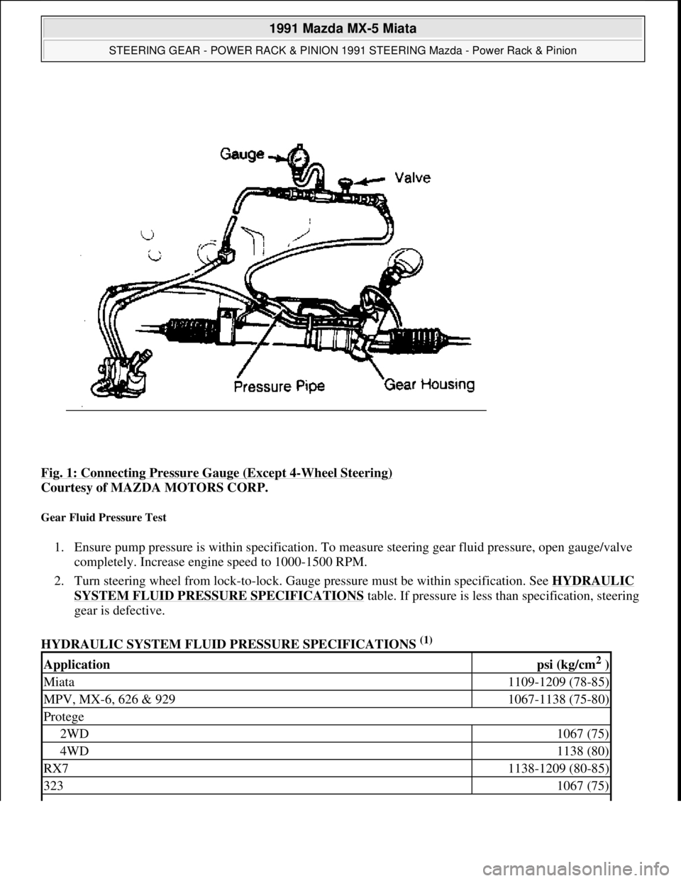
Fig. 1: Connecting Pressure Gauge (Except 4-Wheel Steering)
Courtesy of MAZDA MOTORS CORP.
Gear Fluid Pressure Test
1. Ensure pump pressure is within specification. To measure steering gear fluid pressure, open gauge/valve
completely. Increase engine speed to 1000-1500 RPM.
2. Turn steering wheel from lock-to-lock. Gauge pressure must be within specification. See HYDRAULIC
SYSTEM FLUID PRESSURE SPECIFICATIONStable. If pressure is less than specification, steering
gear is defective.
HYDRAULIC SYSTEM FLUID PRESSURE SPECIFICATIONS
(1)
Applicationpsi (kg/cm2 )
Miata1109-1209 (78-85)
MPV, MX-6, 626 & 9291067-1138 (75-80)
Protege
2WD1067 (75)
4WD1138 (80)
RX71138-1209 (80-85)
3231067 (75)
1991 Mazda MX-5 Miata
STEERING GEAR - POWER RACK & PINION 1991 STEERING Mazda - Power Rack & Pinion
Microsoft
Sunday, July 05, 2009 2:10:15 PMPage 2 © 2005 Mitchell Repair Information Company, LLC.
Page 340 of 392
LUBRICATION
CAPACITY
POWER STEERING FLUID CAPACITY
FLUID TYPE
Dexron-II or M-III are recommended for all vehicles.
FLUID LEVEL CHECK
Check fluid level with engine off. Remove fluid level gauge on oil pump or reservoir. Check fluid level. Fluid
should be between "L" and "H" marks on level gauge dipstick. If fluid level is low, fill through gauge tube.
Recheck fluid level. DO NOT overfill.
HYDRAULIC FLUID BLEEDING
1. Raise and support front of vehicle. With ignition off, turn steering wheel lock-to-lock several times. Add
fluid as necessary. Repeat procedure until fluid level no longer decreases.
2. Start engine and let idle. Turn steering wheel lock-to-lock 5 times. Check fluid level. Add fluid as
necessary. Continue procedure until fluid is clear of air bubbles and does not decrease in level.
ADJUSTMENTS
POWER STEERING BELT ADJUSTMENT
POWER STEERING BELT DEFLECTION
(1)
(1)Specifications are measured at 1000-1500 RPM, with fluid temperature at 122-140°F (50-60°C).
ApplicationQts. (L)
Miata, MPV & 929.95 (.90)
MX-6 & 626
Electronc Controlled Power Steering (ECPS)1.06 (1.0)
Engine Speed (Sensing) Power Steering (ESPS).95 (.90)
Protege & 323.63 (.60)
RX7.85 (.80)
NOTE: On-vehicle adjustment procedures are not available from manufacturer.
ApplicationIn. (mm)
Miata, Protege & 323
New Belt.31-.35 (7.8-8.9)
1991 Mazda MX-5 Miata
STEERING GEAR - POWER RACK & PINION 1991 STEERING Mazda - Power Rack & Pinion
Microsoft
Sunday, July 05, 2009 2:10:15 PMPage 3 © 2005 Mitchell Repair Information Company, LLC.
Page 342 of 392
3. Remove pressure and return hose connections from steering gear. Remove mud flap on driver's side.
Remove steering gear mounting bolts. Remove steering gear through wheelwell on driver's side.
4. To install, reverse removal procedure. Fill and bleed system. Tighten bolts to specification. See
TORQUE SPECIFICATIONS
table.
Removal & Installation (Protege & 323)
1. Disconnect negative battery cable. Raise and support front of vehicle. Remove front wheels. Remove
engine undercover. Remove cotter pins and castle nuts from tie rod ends.
2. Using puller, remove tie rods from steering knuckles. Remove steering column intermediate shaft-to-
steering gear pinion shaft bolt. Remove pressure and return hose connections from steering gear box.
3. Remove all accessible steering gear mounting bracket upper nuts and lower bolts. On Protege, support
drive train from above. Loosen stabilizer bar left mounting bracket and remove engine mount
crossmember.
4. Remove transmission control cable clip. Remove transfer case mount nuts. Lower engine gradually until
rear engine mount bolts can be removed. Remove lower left steering gear mounting bolt from between
transaxle and transfer case.
5. On all models, remove steering gear. To install, reverse removal procedure. Fill and bleed system.
Tighten bolts to specification. See TORQUE SPECIFICATIONS
table.
Removal & Installation (RX7)
1. Remove battery. Drain cooling system. Remove fan shroud and radiator. Raise and support front of
vehicle. Remove front wheels and engine undercover.
2. Remove control links and stabilizer bar. Remove cotter pins and castle nuts from tie rod ends. Remove tie
rods from steering knuckles with puller.
3. Remove steering column intermediate shaft-to-steering gear pinion shaft bolt. Remove pressure and
return hose connections from steering gear box.
4. Remove steering gear mounting bolts. Lower steering gear brackets, steering gear and linkage from
vehicle as an assembly.
5. To install, reverse removal procedure. Fill and bleed system. Tighten bolts to specification. See
TORQUE SPECIFICATIONS
table.
Removal & Installation (929)
1. Disconnect negative battery cable. Raise and support front of vehicle. Remove front wheels. Remove
engine undercover. Disconnect pressure and return hose connections in front of steering gear.
2. Drain fluid. Disconnect return hose fitting to control valve. Remove starter for access to control valve.
Disconnect control valve and pressure switch connectors. Remove control valve. Remove cotter pins and
castle nuts from tie rod ends.
3. Using puller, remove tie rods from steering knuckles. Remove steering column intermediate shaft-to-
steering gear pinion shaft bolt. Remove steering gear mounting bolts. Remove steering gear from bottom
of vehicle.
4. To install, reverse removal procedure. Tighten bolts to specification. See TORQUE SPECIFICATIONS
1991 Mazda MX-5 Miata
STEERING GEAR - POWER RACK & PINION 1991 STEERING Mazda - Power Rack & Pinion
Microsoft
Sunday, July 05, 2009 2:10:15 PMPage 5 © 2005 Mitchell Repair Information Company, LLC.
Page 346 of 392

Fig. 4: Engine Speed Sensing Rack & Pinion Steering Gear (MX6 & 626)
Courtesy of MAZDA MOTORS CORP.
1991 Mazda MX-5 Miata
STEERING GEAR - POWER RACK & PINION 1991 STEERING Mazda - Power Rack & Pinion
Microsoft
Sunday, July 05, 2009 2:10:15 PMPage 9 © 2005 Mitchell Repair Information Company, LLC.
Page 357 of 392
STARTER - DIRECT DRIVE
1990-92 ELECTRICAL Mazda Starters - Direct Drive
DESCRIPTION
Nippondenso direct drive starter is a conventional 12-volt, 4-pole, brush-type starter. The integral solenoid is
attached to the drive housing. The overrunning clutch pinion drive is mounted directly on armature shaft drive
end.
TROUBLESHOOTING
TESTING (ON VEHICLE)
CIRCUIT TESTING
1. Turn ignition switch to START position, depress clutch and ensure starter operates. If starter does not
operate, use voltmeter to check voltage at "S" terminal when clutch is depressed and ignition is turned to
START position. See Fig. 1
.
2. If voltage is less than 8 volts, check starter interlock switch and ignition switch to starter wiring circuit for
short to ground. If voltage is greater than 8 volts and starter is inoperative, starter has an internal fault.
Repair or replace as required. NOTE: For information on B2200 and Protege models with automatic transmissions,
see STARTERS - GEAR REDUCTION article.
NOTE: See TROUBLE SHOOTING - BASIC PROCEDURES article in the GENERAL
INFORMATION section.
NOTE: Before testing, ensure battery is fully charged, battery cables and terminals are
clean and tight and engine grounds are good.
1991 Mazda MX-5 Miata
STARTER - DIRECT DRIVE 1990-92 ELECTRICAL Mazda Starters - Direct Drive
1991 Mazda MX-5 Miata
STARTER - DIRECT DRIVE 1990-92 ELECTRICAL Mazda Starters - Direct Drive
Microsoft
Sunday, July 05, 2009 2:13:20 PMPage 1 © 2005 Mitchell Repair Information Company, LLC.
Microsoft
Sunday, July 05, 2009 2:13:24 PMPage 1 © 2005 Mitchell Repair Information Company, LLC.
Page 386 of 392

Fig. 4: Aligning Camshaft Timing Marks (SOHC Engines)
Courtesy of MAZDA MOTORS CORP.
1991 Mazda MX-5 Miata
MAZDA 1.6L & 1.8L 4-Cylinder - 1986-95
Microsoft
Sunday, July 05, 2009 2:12:44 PMPage 5 © 2005 Mitchell Repair Information Company, LLC.
Page 387 of 392

Fig. 5: Aligning Camshaft Timing Marks (DOHC 1.8L Engines)
Courtesy of MAZDA MOTORS CORP.
Removal (MX-5 Miata - DOHC)
1. Disconnect negative battery cable. Drain cooling system. Remove radiator hose and by-pass hoses from
thermostat housing. Remove air cleaner intake duct assembly from throttle body to air cleaner filter
housing. Remove splash shield.
2. Remove drive belt(s) and water pump pulley. See Fig. 6
. Align crankshaft pulley timing mark with
cylinder No. 1 at TDC of compression stroke. Hold crankshaft pulley stationary. Remove crankshaft
pulley bolts. Remove pulley. Remove crankshaft pulley hub bolt and hub.
3. Remove cylinder head cover. Remove upper, center and lower timing belt cover. If timing belt is to be
reused, mark timing belt rotation direction. Ensure timing marks on camshaft sprockets are aligned. See
Fig. 7
. Loosen timing belt tensioner lock bolt, and move tensioner away from belt with spring fully
expanded. Remove timin
g belt.
1991 Mazda MX-5 Miata
MAZDA 1.6L & 1.8L 4-Cylinder - 1986-95
Microsoft
Sunday, July 05, 2009 2:12:44 PMPage 6 © 2005 Mitchell Repair Information Company, LLC.
Page 390 of 392

Check timing belt for cracks, peeling, abrasion or other damage. Check tensioner bearing for looseness or
roughness of rotation. Inspect tensioner spring for stretching. Replace parts as necessary.
Installation (All Models)
1. Position notch on crankshaft sprocket to 12 o'clock position (aligned with mark on oil pump). Align
timing marks on camshaft sprocket(s). For SOHC, see Fig. 4
. For DOHC, see Fig. 5 or Fig. 7 . Ensure
crankshaft timing mark is at TDC. Install belt around crankshaft sprocket, then working in a
counterclockwise direction, route belt around camshaft sprocket(s).
2. Loosen timing belt tensioner lock bolt, and allow spring to apply tension on belt. Snug tensioner lock
bolt. Rotate crankshaft 2 complete turns in direction of normal engine rotation. Ensure timing marks
align. If timing marks are not aligned, remove belt, realign all timing marks, and repeat installation
procedure.
3. On all engines, check timing belt deflection with 22 lbs. (10 kg) of pressure applied to belt. See Fig. 8
.
Ensure timing belt deflection is within specification. See TIMING BELT DEFLECTION
table. Adjust
drive belts to proper tension.
TIMING BELT DEFLECTION
Application(1) Deflection - In. (mm)
1986-89.47-.51 (11.9-13.0)
1990-95
DOHC.35-.45 (9.0-11.5)
SOHC.43-.51 (11.0-13.0)
(1)Deflection measurement is with 22 lbs. (10 kg) of pressure applied to timing belt. See Fig. 8.
1991 Mazda MX-5 Miata
MAZDA 1.6L & 1.8L 4-Cylinder - 1986-95
Microsoft
Sunday, July 05, 2009 2:12:44 PMPage 9 © 2005 Mitchell Repair Information Company, LLC.