engine MAZDA MIATA 1991 Factory Owner's Manual
[x] Cancel search | Manufacturer: MAZDA, Model Year: 1991, Model line: MIATA, Model: MAZDA MIATA 1991Pages: 392, PDF Size: 29.45 MB
Page 291 of 392
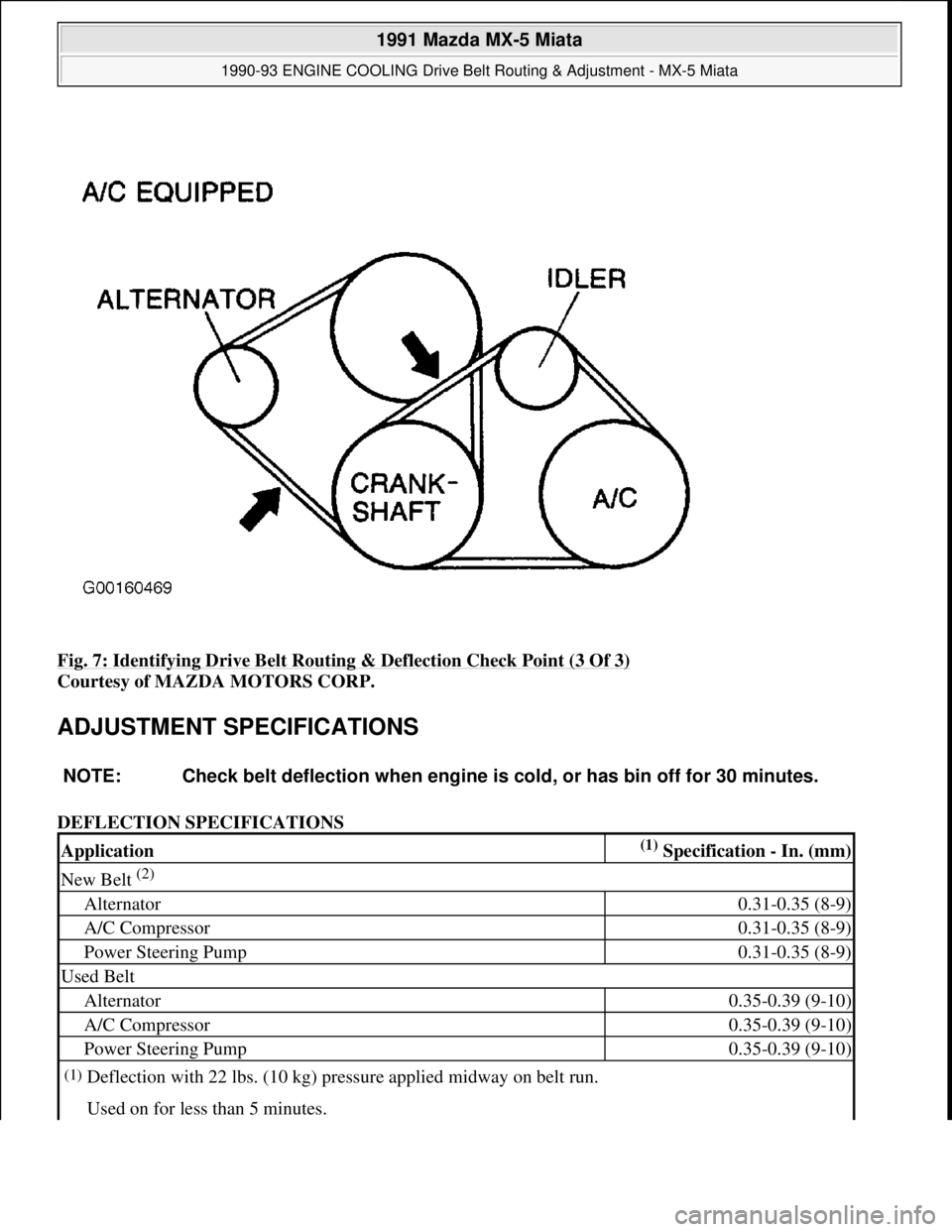
Fig. 7: Identifying Drive Belt Routing & Deflection Check Point (3 Of 3)
Courtesy of MAZDA MOTORS CORP.
ADJUSTMENT SPECIFICATIONS
DEFLECTION SPECIFICATIONS
NOTE: Check belt deflection when engine is cold, or has bin off for 30 minutes.
Application(1) Specification - In. (mm)
New Belt (2)
Alternator0.31-0.35 (8-9)
A/C Compressor0.31-0.35 (8-9)
Power Steering Pump0.31-0.35 (8-9)
Used Belt
Alternator0.35-0.39 (9-10)
A/C Compressor0.35-0.39 (9-10)
Power Steering Pump0.35-0.39 (9-10)
(1)Deflection with 22 lbs. (10 kg) pressure applied midway on belt run.
Used on for less than 5 minutes.
1991 Mazda MX-5 Miata
1990-93 ENGINE COOLING Drive Belt Routing & Adjustment - MX-5 Miata
Microsoft
Sunday, July 05, 2009 2:14:16 PMPage 7 © 2005 Mitchell Repair Information Company, LLC.
Page 292 of 392
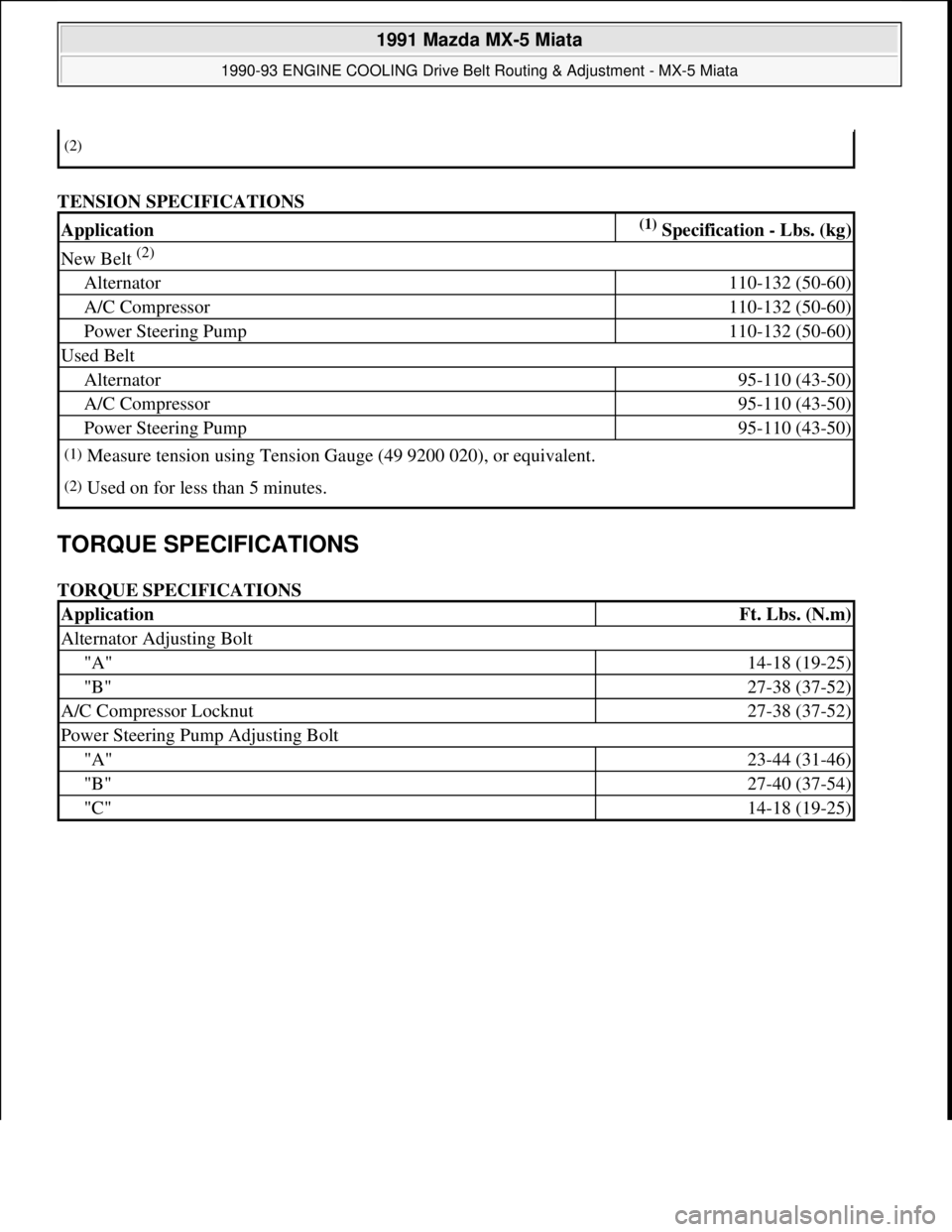
TENSION SPECIFICATIONS
TORQUE SPECIFICATIONS
TORQUE SPECIFICATIONS
(2)
Application(1) Specification - Lbs. (kg)
New Belt (2)
Alternator110-132 (50-60)
A/C Compressor110-132 (50-60)
Power Steering Pump110-132 (50-60)
Used Belt
Alternator95-110 (43-50)
A/C Compressor95-110 (43-50)
Power Steering Pump95-110 (43-50)
(1)Measure tension using Tension Gauge (49 9200 020), or equivalent.
(2)Used on for less than 5 minutes.
ApplicationFt. Lbs. (N.m)
Alternator Adjusting Bolt
"A"14-18 (19-25)
"B"27-38 (37-52)
A/C Compressor Locknut27-38 (37-52)
Power Steering Pump Adjusting Bolt
"A"23-44 (31-46)
"B"27-40 (37-54)
"C"14-18 (19-25)
1991 Mazda MX-5 Miata
1990-93 ENGINE COOLING Drive Belt Routing & Adjustment - MX-5 Miata
Microsoft
Sunday, July 05, 2009 2:14:16 PMPage 8 © 2005 Mitchell Repair Information Company, LLC.
Page 293 of 392
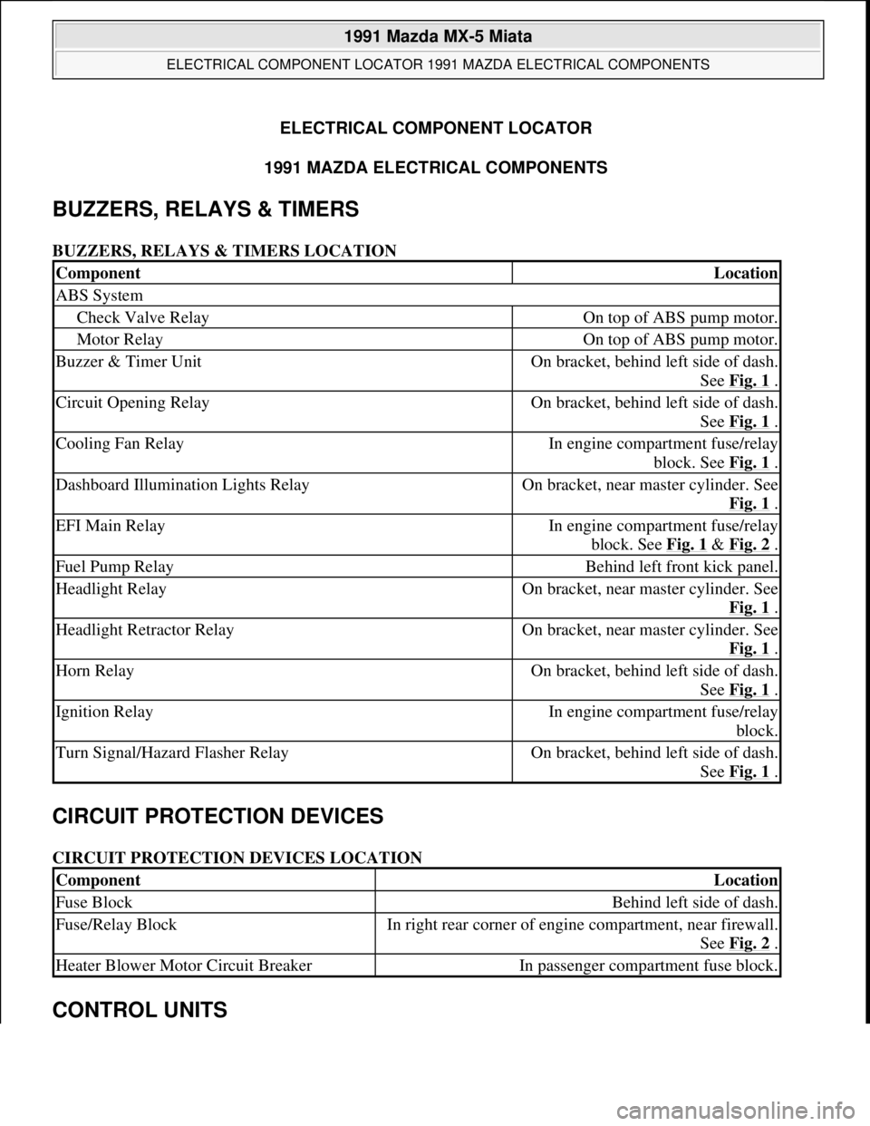
ELECTRICAL COMPONENT LOCATOR
1991 MAZDA ELECTRICAL COMPONENTS
BUZZERS, RELAYS & TIMERS
BUZZERS, RELAYS & TIMERS LOCATION
CIRCUIT PROTECTION DEVICES
CIRCUIT PROTECTION DEVICES LOCATION
CONTROL UNITS
ComponentLocation
ABS System
Check Valve RelayOn top of ABS pump motor.
Motor RelayOn top of ABS pump motor.
Buzzer & Timer UnitOn bracket, behind left side of dash.
See Fig. 1
.
Circuit Opening RelayOn bracket, behind left side of dash.
See Fig. 1
.
Cooling Fan RelayIn engine compartment fuse/relay
block. See Fig. 1
.
Dashboard Illumination Lights RelayOn bracket, near master cylinder. See
Fig. 1
.
EFI Main RelayIn engine compartment fuse/relay
block. See Fig. 1
& Fig. 2 .
Fuel Pump RelayBehind left front kick panel.
Headlight RelayOn bracket, near master cylinder. See
Fig. 1
.
Headlight Retractor RelayOn bracket, near master cylinder. See
Fig. 1
.
Horn RelayOn bracket, behind left side of dash.
See Fig. 1
.
Ignition RelayIn engine compartment fuse/relay
block.
Turn Signal/Hazard Flasher RelayOn bracket, behind left side of dash.
See Fig. 1
.
ComponentLocation
Fuse BlockBehind left side of dash.
Fuse/Relay BlockIn right rear corner of engine compartment, near firewall.
See Fig. 2
.
Heater Blower Motor Circuit BreakerIn passenger compartment fuse block.
1991 Mazda MX-5 Miata
ELECTRICAL COMPONENT LOCATOR 1991 MAZDA ELECTRICAL COMPONENTS
1991 Mazda MX-5 Miata
ELECTRICAL COMPONENT LOCATOR 1991 MAZDA ELECTRICAL COMPONENTS
Microsoft
Sunday, July 05, 2009 2:15:23 PMPage 1 © 2005 Mitchell Repair Information Company, LLC.
Microsoft
Sunday, July 05, 2009 2:15:28 PMPage 1 © 2005 Mitchell Repair Information Company, LLC.
Page 294 of 392
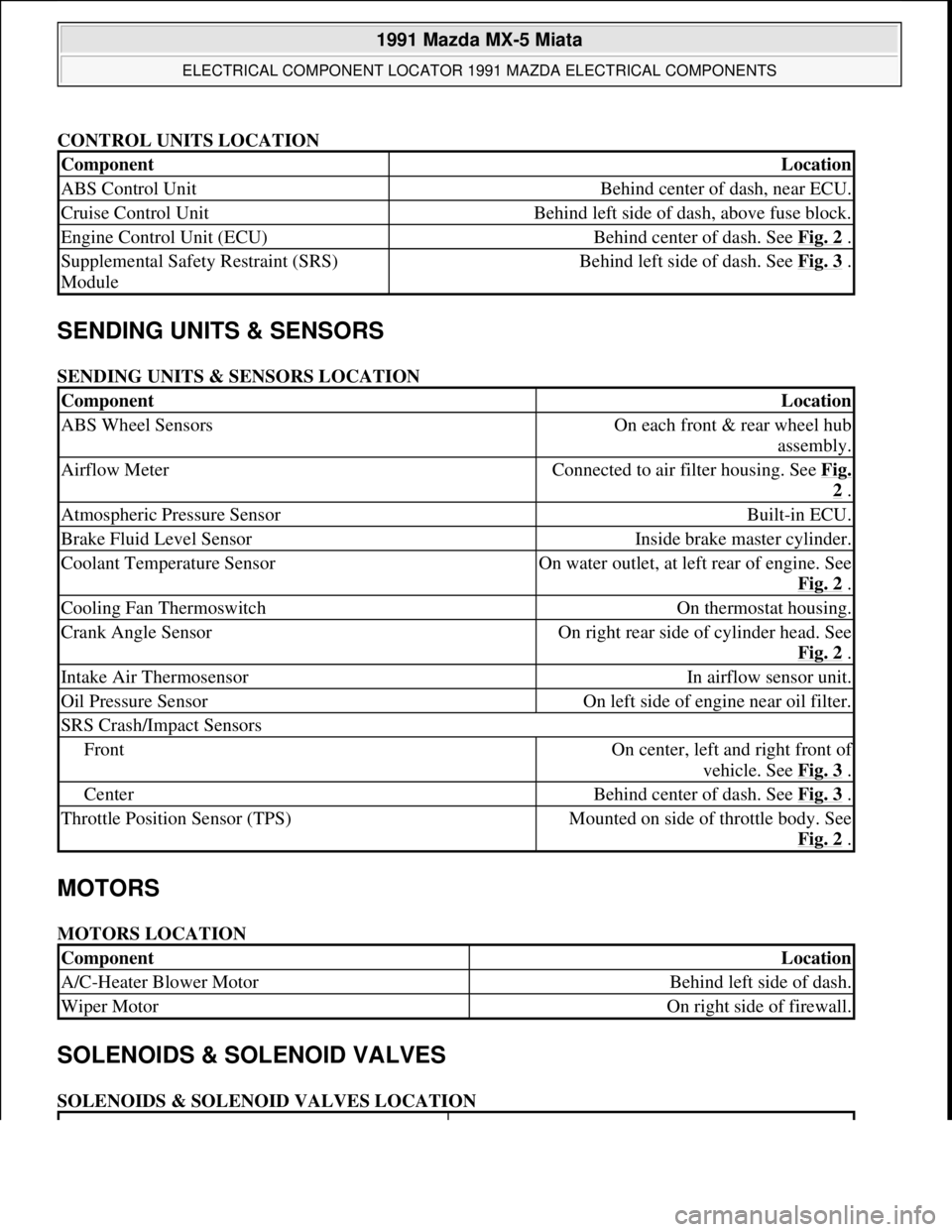
CONTROL UNITS LOCATION
SENDING UNITS & SENSORS
SENDING UNITS & SENSORS LOCATION
MOTORS
MOTORS LOCATION
SOLENOIDS & SOLENOID VALVES
SOLENOIDS & SOLENOID VALVES LOCATION
ComponentLocation
ABS Control UnitBehind center of dash, near ECU.
Cruise Control UnitBehind left side of dash, above fuse block.
Engine Control Unit (ECU)Behind center of dash. See Fig. 2 .
Supplemental Safety Restraint (SRS)
ModuleBehind left side of dash. See Fig. 3 .
ComponentLocation
ABS Wheel SensorsOn each front & rear wheel hub
assembly.
Airflow MeterConnected to air filter housing. See Fig.
2 .
Atmospheric Pressure SensorBuilt-in ECU.
Brake Fluid Level SensorInside brake master cylinder.
Coolant Temperature SensorOn water outlet, at left rear of engine. See
Fig. 2
.
Cooling Fan ThermoswitchOn thermostat housing.
Crank Angle SensorOn right rear side of cylinder head. See
Fig. 2
.
Intake Air ThermosensorIn airflow sensor unit.
Oil Pressure SensorOn left side of engine near oil filter.
SRS Crash/Impact Sensors
FrontOn center, left and right front of
vehicle. See Fig. 3
.
CenterBehind center of dash. See Fig. 3 .
Throttle Position Sensor (TPS)Mounted on side of throttle body. See
Fig. 2
.
ComponentLocation
A/C-Heater Blower MotorBehind left side of dash.
Wiper MotorOn right side of firewall.
1991 Mazda MX-5 Miata
ELECTRICAL COMPONENT LOCATOR 1991 MAZDA ELECTRICAL COMPONENTS
Microsoft
Sunday, July 05, 2009 2:15:23 PMPage 2 © 2005 Mitchell Repair Information Company, LLC.
Page 295 of 392
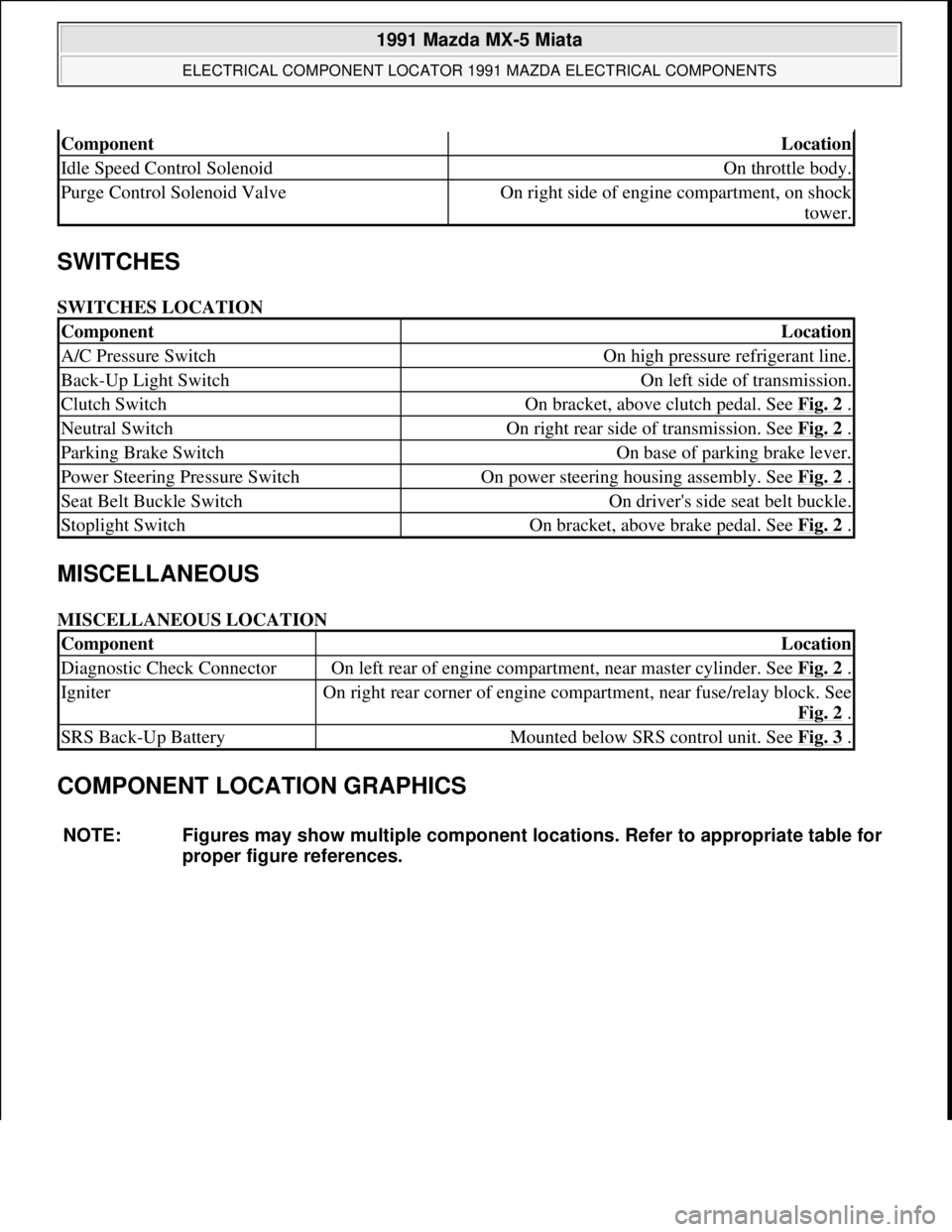
SWITCHES
SWITCHES LOCATION
MISCELLANEOUS
MISCELLANEOUS LOCATION
COMPONENT LOCATION GRAPHICS
ComponentLocation
Idle Speed Control SolenoidOn throttle body.
Purge Control Solenoid ValveOn right side of engine compartment, on shock
tower.
ComponentLocation
A/C Pressure SwitchOn high pressure refrigerant line.
Back-Up Light SwitchOn left side of transmission.
Clutch SwitchOn bracket, above clutch pedal. See Fig. 2 .
Neutral SwitchOn right rear side of transmission. See Fig. 2 .
Parking Brake SwitchOn base of parking brake lever.
Power Steering Pressure SwitchOn power steering housing assembly. See Fig. 2 .
Seat Belt Buckle SwitchOn driver's side seat belt buckle.
Stoplight SwitchOn bracket, above brake pedal. See Fig. 2 .
ComponentLocation
Diagnostic Check ConnectorOn left rear of engine compartment, near master cylinder. See Fig. 2 .
IgniterOn right rear corner of engine compartment, near fuse/relay block. See
Fig. 2
.
SRS Back-Up BatteryMounted below SRS control unit. See Fig. 3 .
NOTE: Figures may show multiple component locations. Refer to appropriate table for
proper figure references.
1991 Mazda MX-5 Miata
ELECTRICAL COMPONENT LOCATOR 1991 MAZDA ELECTRICAL COMPONENTS
Microsoft
Sunday, July 05, 2009 2:15:23 PMPage 3 © 2005 Mitchell Repair Information Company, LLC.
Page 306 of 392

LOWER CONTROL ARM
Removal
Raise and support vehicle. Remove wheel assembly. Remove engine splash shield (if equipped). Remove
stabilizer bar from lower control arm. Remove strut rod (if equipped). Remove ball joint clamp bolt or pivot
nut, and separate ball joint from steering knuckle. Remove lower control arm pivot bolts. Remove lower control
arm.
Inspection
Check lower control arm for damage or cracks. Check bushings for deterioration and excessive wear. Check
ball joint for excessive wear. Examine dust boot for damage. Replace parts as necessary.
Bushing Replacement (Miata)
Cut or press old bushing from control arm. Coat new bushing with paraffin-based oil. Press new bushing into
control arm. To install, reverse removal procedure.
Bushing Replacement (MPV 4WD)
Cut away bushing inner collar. Using a vise and Remover/Installer (49-G033-102 and 49-FO27-009), push out
front bushing. Press out rear bushing using a press and Remover/Installer (49-U034-202 and 49-GO26-103). To
install front bushing, apply soapy water to bushing and use remover/installer to press in. To install rear bushing,
align arrows on bushing with marks on lower arm and use remover/installer to press in.
Bushing Replacement (MX-6 & 626)
Cut away bushing inner collar. Using a vise and Remover/Installer (49-GO34-2A0), push out bushing. To
install, apply soapy water to bushing and use remover/installer to press in. Always install bushing from outer
side of arm. Press in bushing until collar contacts arm.
Bushing Replacement (Protege & 323)
Using a vise and Remover/Installer Set (49-BO34-2A0), push out bushing. To install, apply soapy water to
bushing and use remover/installer to press in. Always install bushing from outer side of arm. Press in bushing
until collar contacts arm.
Bushing Replacement (929)
Cut away bushing outer collar. Using a vise and Remover/Installer (49-HO34-202 and 49-HO34-201), remove
bushing from control arm. To install, reverse removal procedure.
Bushing Replacement (RX7)
NOTE: Lower control arm bushings are not replaceable on MPV 2WD models. Replace
control arm assembly if bushings are worn or damaged.
1991 Mazda MX-5 Miata
SUSPENSION - FRONT 1990-91 SUSPENSION Front
Microsoft
Sunday, July 05, 2009 2:08:54 PMPage 8 © 2005 Mitchell Repair Information Company, LLC.
Page 307 of 392

Push out front bushing using a press and Remover (49-G030-627A). To remove rear bushing, install Bearing
Puller (49-0710-520) on bushing. DO NOT overtighten bearing puller nuts or lower arm will be distorted and
damaged. Press to push out rear bushing using Remover (49-G030-627A). To install both bushings, use
remover and Support Block (49-0823-146).
Installation (All Models)
To install, reverse removal procedure. Tighten lower control arm pivot bolts to specification with vehicle
resting on ground and suspension unloaded. See TORQUE SPECIFICATIONS
.
UPPER CONTROL ARM
Removal (Miata)
Raise and support vehicle. Remove wheel assembly. Remove engine splash shield. Remove ball joint pivot nut.
Use Puller (49-0118-850C) to separate ball joint from steering knuckle. Remove upper control arm pivot bolts.
Remove upper control arm.
Inspection
Check upper control arm for damage or cracks. Check bushings for deterioration and excessive wear. Check
ball joint for excessive wear. Examine dust boot for damage. Replace parts as necessary.
Bushing Replacement
Using a chisel, remove old bushing from control arm. Coat new bushing with grease. Press new bushing into
control arm.
Installation
To install, reverse removal procedure. Tighten upper control arm pivot bolts to specification with vehicle
resting on ground and suspension unloaded.
SHOCK ABSORBER
Removal (Miata)
Raise and support vehicle. Remove wheel assembly. Remove engine splash shield. Remove stabilizer link bolt.
Separate upper ball joint from steering knuckle. Loosen lower control arm pivot bolts. Remove shock absorber
upper mount nuts and lower bolt. Move lower control arm just enough to remove shock absorber. Be careful not
to damage brake line.
Disassembly
Clamp upper mount in vise. Loosen lock nut 2 turns only. Compress coil spring using coil spring compressor.
Remove lock nut and remainin
g components. Slowly release compressor tension.
1991 Mazda MX-5 Miata
SUSPENSION - FRONT 1990-91 SUSPENSION Front
Microsoft
Sunday, July 05, 2009 2:08:54 PMPage 9 © 2005 Mitchell Repair Information Company, LLC.
Page 310 of 392

Fig. 7: Positioning Strut for Installation (MX-6, Protege, 323 & 626)
Courtesy of MAZDA MOTORS CORP.
STABILIZER BAR
Removal & Installation
1. Raise and support vehicle. Remove engine splash shield (if equipped). Remove mounting hardware and
stabilizer bar. Note position of frame bushing seam. Inspect all components for wear, bends or damage.
2. Install frame bushing so it aligns with painted line on stabilizer bar. Install and partially tighten remaining
components. Final tighten all bolts with vehicle resting on ground and suspension unloaded.
TORQUE SPECIFICATIONS
TORQUE SPECIFICATIONS
ApplicationFt. Lbs. (N.m)
Miata
Brake Caliper Bracket Bolts36-51 (49-69)
Drive Axle Lock Nut123-159 (167-216)
Lower Ball Joint-To-Knuckle Nut43-57 (58-77)
Lower Ball Joint-To-Lower Control Arm Nut54-69 (73-93)
1991 Mazda MX-5 Miata
SUSPENSION - FRONT 1990-91 SUSPENSION Front
Microsoft
Sunday, July 05, 2009 2:08:54 PMPage 12 © 2005 Mitchell Repair Information Company, LLC.
Page 314 of 392
FUSES & CIRCUIT BREAKERS
Fuses & Circuit Breakers 1990-95 Mazda
FUSES & CIRCUIT BREAKERS
FUSE PANEL LOCATION
Fuse box is located above driver's left knee, accessible through a removable cover. The main fuse block is
located at the right rear of the engine compartment.
The Trunk Mounted Fuse Panel is located on the right side of the trunk, near the trunk hinge. (1992-95 Models)
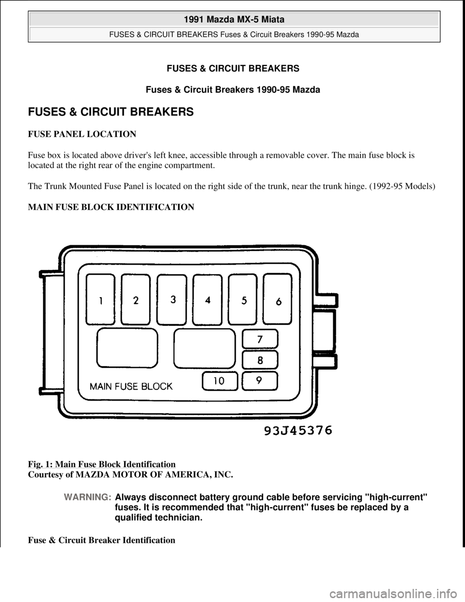
MAIN FUSE BLOCK IDENTIFICATION
Fig. 1: Main Fuse Block Identification
Courtesy of MAZDA MOTOR OF AMERICA, INC.
Fuse & Circuit Breaker Identification
WARNING:Always disconnect battery ground cable before servicing "high-current"
fuses. It is recommended that "high-current" fuses be replaced by a
qualified technician.
1991 Mazda MX-5 Miata
FUSES & CIRCUIT BREAKERS Fuses & Circuit Breakers 1990-95 Mazda
1991 Mazda MX-5 Miata
FUSES & CIRCUIT BREAKERS Fuses & Circuit Breakers 1990-95 Mazda
Microsoft
Sunday, July 05, 2009 2:15:54 PMPage 1 © 2005 Mitchell Repair Information Company, LLC.
Microsoft
Sunday, July 05, 2009 2:15:57 PMPage 1 © 2005 Mitchell Repair Information Company, LLC.
Page 317 of 392
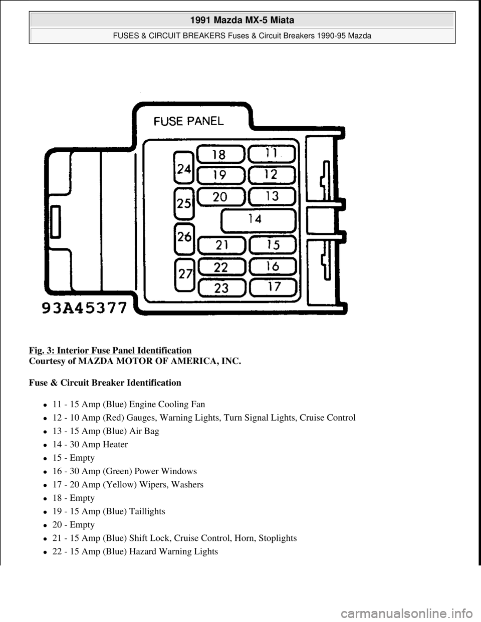
Fig. 3: Interior Fuse Panel Identification
Courtesy of MAZDA MOTOR OF AMERICA, INC.
Fuse & Circuit Breaker Identification
11 - 15 Amp (Blue) Engine Cooling Fan
12 - 10 Amp (Red) Gauges, Warning Lights, Turn Signal Lights, Cruise Control
13 - 15 Amp (Blue) Air Bag
14 - 30 Amp Heater
15 - Empty
16 - 30 Amp (Green) Power Windows
17 - 20 Amp (Yellow) Wipers, Washers
18 - Empty
19 - 15 Amp (Blue) Taillights
20 - Empty
21 - 15 Amp (Blue) Shift Lock, Cruise Control, Horn, Stoplights
22 - 15 Amp (Blue) Hazard Warning Lights
1991 Mazda MX-5 Miata
FUSES & CIRCUIT BREAKERS Fuses & Circuit Breakers 1990-95 Mazda
Microsoft
Sunday, July 05, 2009 2:15:54 PMPage 4 © 2005 Mitchell Repair Information Company, LLC.