center console MAZDA MIATA 1991 Factory Service Manual
[x] Cancel search | Manufacturer: MAZDA, Model Year: 1991, Model line: MIATA, Model: MAZDA MIATA 1991Pages: 392, PDF Size: 29.45 MB
Page 211 of 392

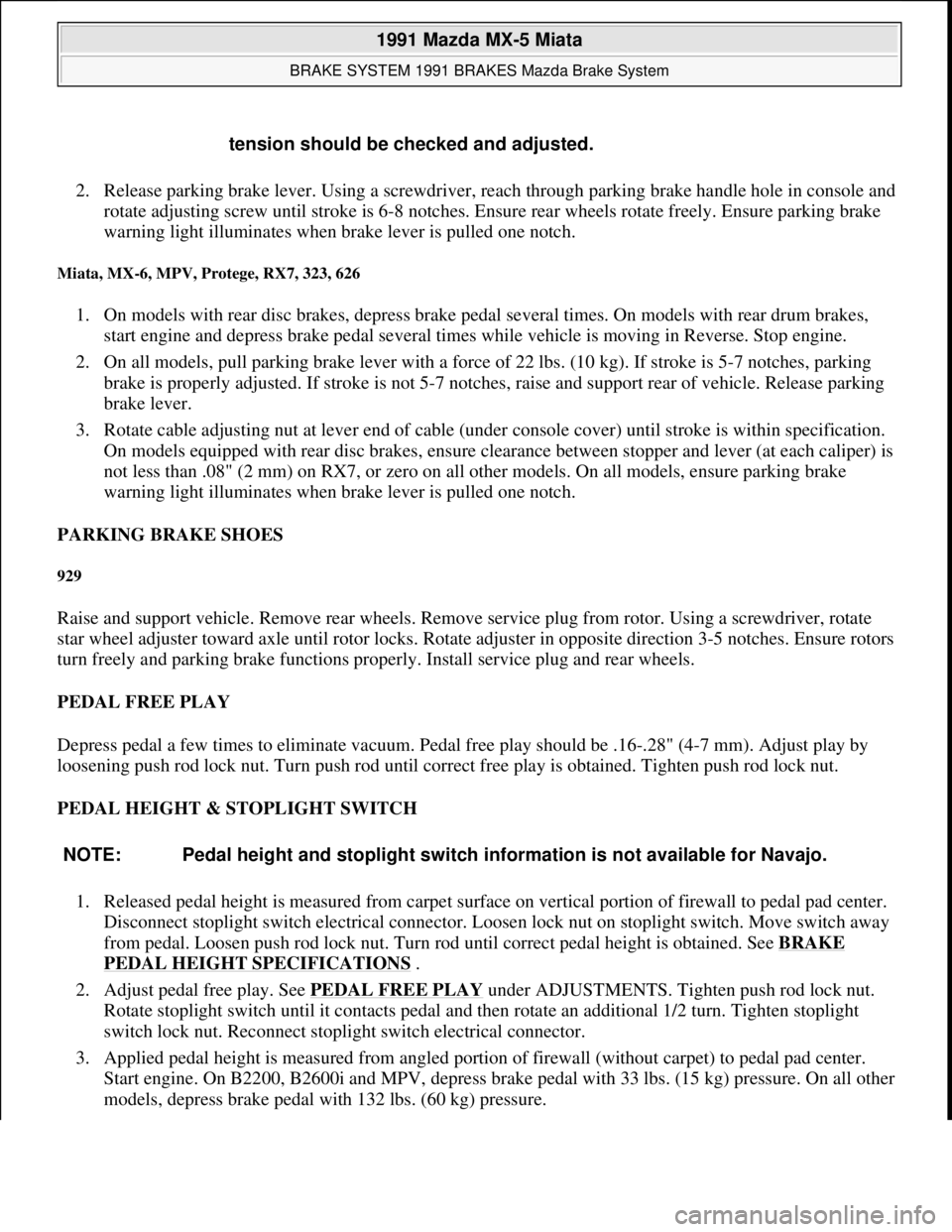
2. Release parking brake lever. Using a screwdriver, reach through parking brake handle hole in console and
rotate adjusting screw until stroke is 6-8 notches. Ensure rear wheels rotate freely. Ensure parking brake
warning light illuminates when brake lever is pulled one notch.
Miata, MX-6, MPV, Protege, RX7, 323, 626
1. On models with rear disc brakes, depress brake pedal several times. On models with rear drum brakes,
start engine and depress brake pedal several times while vehicle is moving in Reverse. Stop engine.
2. On all models, pull parking brake lever with a force of 22 lbs. (10 kg). If stroke is 5-7 notches, parking
brake is properly adjusted. If stroke is not 5-7 notches, raise and support rear of vehicle. Release parking
brake lever.
3. Rotate cable adjusting nut at lever end of cable (under console cover) until stroke is within specification.
On models equipped with rear disc brakes, ensure clearance between stopper and lever (at each caliper) is
not less than .08" (2 mm) on RX7, or zero on all other models. On all models, ensure parking brake
warning light illuminates when brake lever is pulled one notch.
PARKING BRAKE SHOES
929
Raise and support vehicle. Remove rear wheels. Remove service plug from rotor. Using a screwdriver, rotate
star wheel adjuster toward axle until rotor locks. Rotate adjuster in opposite direction 3-5 notches. Ensure rotors
turn freely and parking brake functions properly. Install service plug and rear wheels.
PEDAL FREE PLAY
Depress pedal a few times to eliminate vacuum. Pedal free play should be .16-.28" (4-7 mm). Adjust play by
loosening push rod lock nut. Turn push rod until correct free play is obtained. Tighten push rod lock nut.
PEDAL HEIGHT & STOPLIGHT SWITCH
1. Released pedal height is measured from carpet surface on vertical portion of firewall to pedal pad center.
Disconnect stoplight switch electrical connector. Loosen lock nut on stoplight switch. Move switch away
from pedal. Loosen push rod lock nut. Turn rod until correct pedal height is obtained. See BRAKE
PEDAL HEIGHT SPECIFICATIONS .
2. Adjust pedal free play. See PEDAL FREE PLAY
under ADJUSTMENTS. Tighten push rod lock nut.
Rotate stoplight switch until it contacts pedal and then rotate an additional 1/2 turn. Tighten stoplight
switch lock nut. Reconnect stoplight switch electrical connector.
3. Applied pedal height is measured from angled portion of firewall (without carpet) to pedal pad center.
Start engine. On B2200, B2600i and MPV, depress brake pedal with 33 lbs. (15 kg) pressure. On all other
models, depress brake pedal with 132 lbs. (60 k
g) pressure. tension should be checked and adjusted.
NOTE: Pedal height and stoplight switch information is not available for Navajo.
1991 Mazda MX-5 Miata
BRAKE SYSTEM 1991 BRAKES Mazda Brake System
Microsoft
Sunday, July 05, 2009 2:18:08 PMPage 8 © 2005 Mitchell Repair Information Company, LLC.
Page 324 of 392

Fig. 2: Testing Blower Switch
Courtesy of MAZDA MOTORS CORP.
REMOVAL & INSTALLATION
CONTROL PANEL
Removal & Installation
Remove rear center console assembly. Remove vent outlets from center panel assembly. Remove center panel
assembly. Remove control panel screws. Pull control panel from center panel and disconnect cables. To install,
reverse removal procedure.
HEATER CORE
Removal & Installation
WARNING:To avoid injury from accidental air bag deployment, read and carefully
follow all SERVICE PRECAUTIONS and DISABLING & ACTIVATING AIR
BAG SYSTEM procedures in AIR BAG article in the
ACCESSORIES/SAFETY EQUIPMENT Section.
1991 Mazda MX-5 Miata
HEATER SYSTEM 1990-92 Heater Systems
Microsoft
Sunday, July 05, 2009 2:12:14 PMPage 4 © 2005 Mitchell Repair Information Company, LLC.
Page 333 of 392

Disconnect electrical connectors from blower case. Remove glove box. Loosen seal plate between blower motor
case and evaporator case. Remove blower motor case nuts. Remove case and seal plate. To install, reverse
removal procedure.
COMPRESSOR
Removal & Installation
1. Disconnect negative battery cable. Discharge A/C system using approved refrigerant recovery/recycling
equipment. Disconnect compressor clutch connector. Disconnect refrigerant lines from compressor.
Remove drive belt.
2. Raise and support vehicle. Remove compressor mounting bolts and remove compressor. To install,
reverse removal procedure. Adjust drive belt to specified tension. Evacuate and charge system.
CONDENSER & RECEIVER-DRIER
Removal & Installation
Discharge A/C system using approved refrigerant recovery/recycling equipment. Raise and support vehicle.
Remove splash shield and air guide. Remove condenser and receiver-drier as an assembly. To install, reverse
removal procedure. Evacuate and charge system.
CONTROL PANEL
Removal & Installation
Remove rear console assembly. See Fig. 4 . Remove vent outlets from center panel assembly. Remove center
panel assembly. Remove control panel screws. Pull control panel from hole. Disconnect door control cables
from back of control panel and remove panel. To install, reverse removal procedure.
EVAPORATOR CORE & THERMOSWITCH
Removal & Installation
1. Discharge A/C system using approved refrigerant recovery/recycling equipment. Remove condenser and
receiver-drier as an assembly. Disconnect low-pressure and high-pressure pipes from evaporator tubes at
engine compartment firewall.
2. Remove right undercover and glove box. Disconnect thermoswitch electrical connector. Loosen left seal
plate (between heater case and evaporator case). Loosen right seal plate (between evaporator case and
blower motor case).
3. Remove evaporator case. Disassemble evaporator case, and remove evaporator core and thermoswitch.
See Fig. 3
. To install, reverse removal procedure. Evacuate and charge system.
1991 Mazda MX-5 Miata
A/C-HEATER SYSTEM - MANUAL 1990-92 Manual A/C-Heater Systems
Microsoft
Sunday, July 05, 2009 2:11:52 PMPage 7 © 2005 Mitchell Repair Information Company, LLC.