check engine MAZDA MX-5 1994 Owners Manual
[x] Cancel search | Manufacturer: MAZDA, Model Year: 1994, Model line: MX-5, Model: MAZDA MX-5 1994Pages: 1708, PDF Size: 82.34 MB
Page 268 of 1708
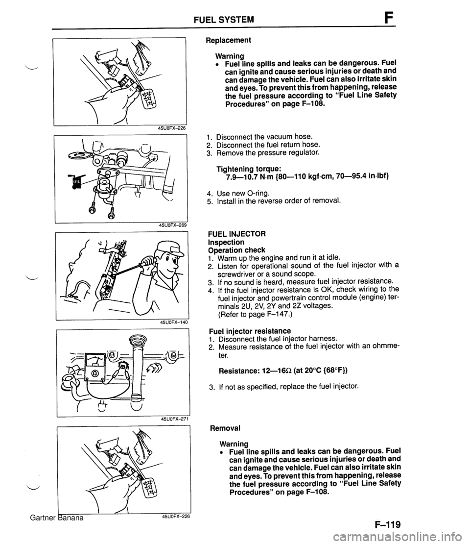
FUEL SYSTEM F Replacement Warning Fuel line spills and leaks can be dangerous. Fuel can ignite and cause serious injuries or death and can damage the vehicle. Fuel can also irritate skin and eyes. To prevent this from happening, release the fuel pressure according to "Fuel Line Safety Procedures" on page F-108. 1. Disconnect the vacuum hose. 2. Disconnect the fuel return hose. 3. Remove the pressure regulator. Tightening torque: 7.9-10.7 N.m (80-11 0 kgf-cm, 70-95.4 in4bf) 4. Use new O-ring. 5. Install in the reverse order of removal. FUEL INJECTOR Inspection Operation check 1. Warm up the engine and run it at idle. 2. Listen for operational sound of the fuel injector with a screwdriver or a sound scope. 3. If no sound is heard, measure fuel injector resistance. 4. If the fuel injector resistance is OK, check wiring to the fuel injector and powertrain control module (engine) ter- minals 2U, 2V1 2Y and 22 voltages. (Refer to page F-147.) Fuel injector resistance 1. Disconnect the fuel injector harness. 2. Measure resistance of the fuel injector with an ohmme- ter. Resistance: 12-16Q (at 20°C (68°F)) 3. If not as specified, replace the fuel injector. Removal Warning Fuel line spills and leaks can be dangerous. Fuel can ignite and cause serious injuries or death and can damage the vehicle. Fuel can also irritate skin and eyes. To prevent this from happening, release the fuel pressure according to "Fuel Line Safety Procedures" on page F-108. Gartner Banana
Page 270 of 1708
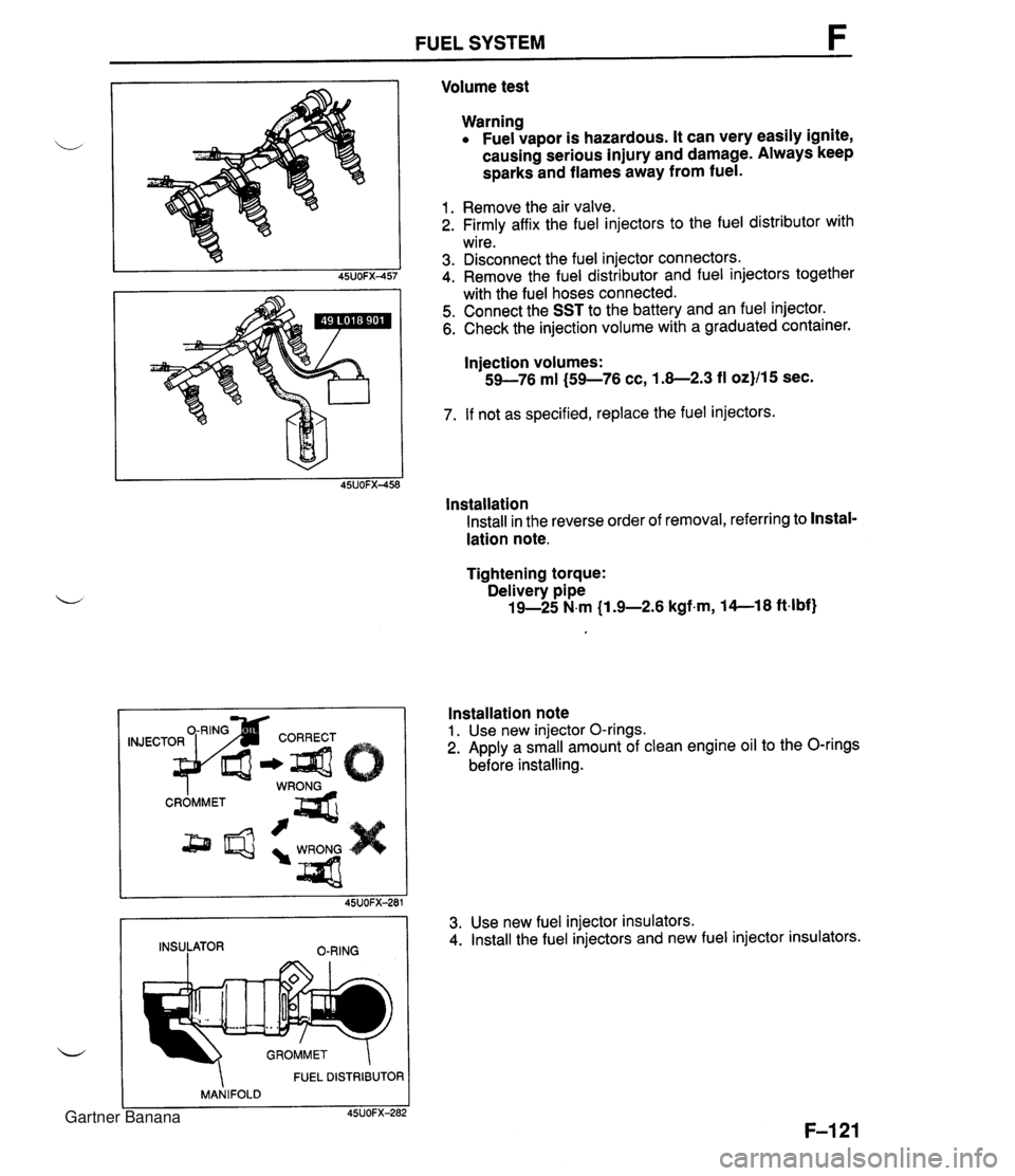
FUEL SYSTEM Volume test Warning Fuel vapor is hazardous. It can very easily ignite, causing serious injury and damage. Always keep sparks and flames away from fuel. 1. Remove the air valve. 2. Firmly affix the fuel injectors to the fuel distributor with wire. 3. Disconnect the fuel injector connectors. 4. Remove the fuel distributor and fuel injectors together with the fuel hoses connected. 5. Connect the SST to the battery and an fuel injector. 6. Check the injection volume with a graduated container. Injection volumes: 59-76 ml (59-76 cc, 1.8-2.3 fl oz}/15 sec. 7. If not as specified, replace the fuel injectors. lnstallation Install in the reverse order of removal, referring to Instal- lation note. Tightening torque: Delivery pipe 19-25 N.m (1 .%2.6 kgfm, 14--18 ft4bf) FUEL DISTRIBUTOR MANIFOLD C 45UOFX-282 Installation note 1. Use new injector O-rings. 2. Apply a small amount of clean engine oil to the O-rings before installing. 45UOFX-281 INSULATOR O-RING 3. Use new fuel injector insulators. 4. Install the fuel injectors and new fuel injector insulators. Gartner Banana
Page 272 of 1708
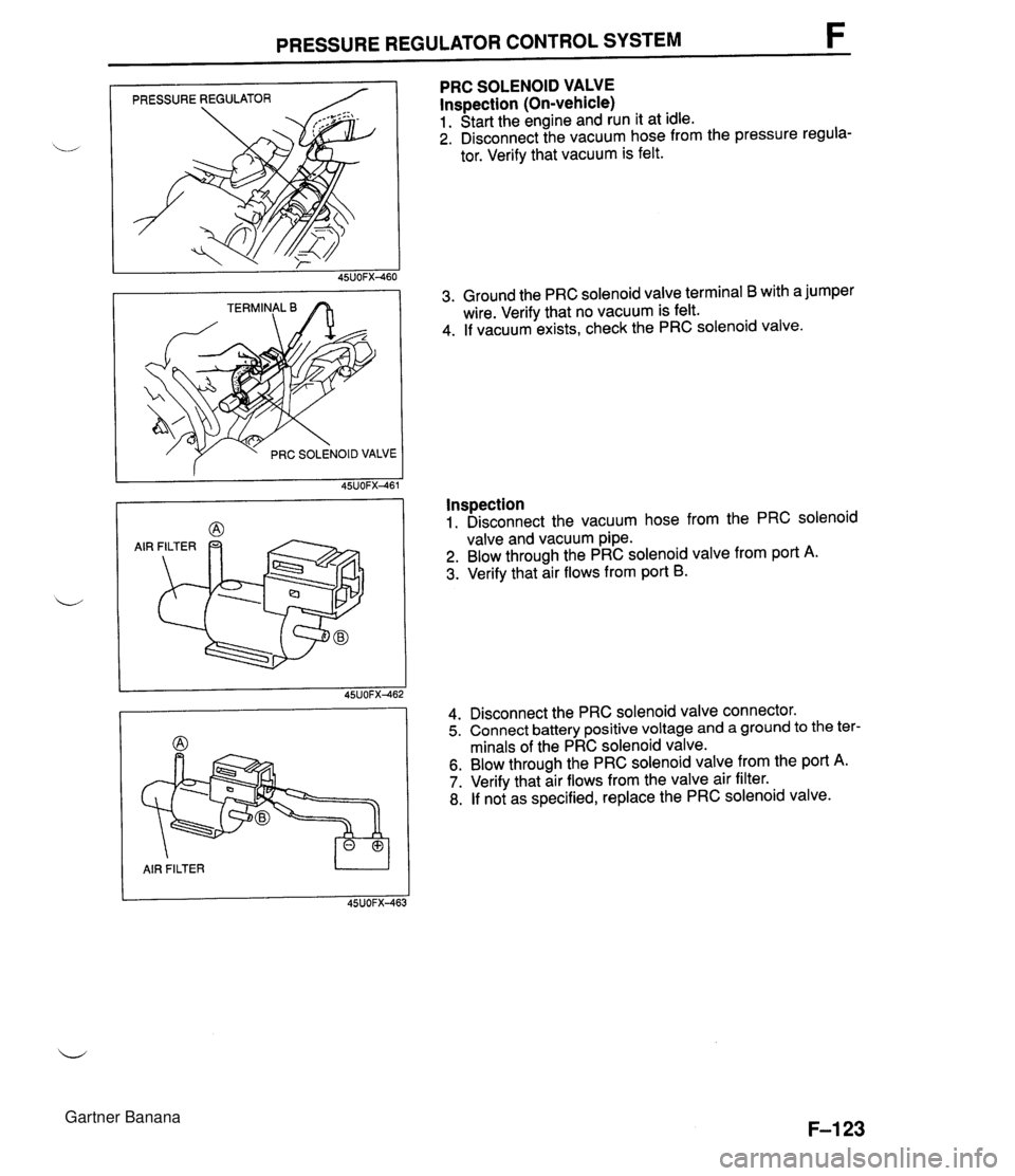
PRESSURE REGULATOR CONTROL SYSTEM F PRESSURE REGULATOR / f PRC SOLENOID VALVE AIR FILTER U PRC SOLENOID VALVE lnspection (On-vehicle) 1. Start the engine and run it at idle. 2. Disconnect the vacuum hose from the pressure regula- tor. Verify that vacuum is felt. 3. Ground the PRC solenoid valve terminal B with a jumper wire. Verify that no vacuum is felt. 4. If vacuum exists, check the PRC solenoid valve. Inspection 1. Disconnect the vacuum hose from the PRC solenoid valve and vacuum pipe. 2. Blow through the PRC solenoid valve from port A. 3. Verify that air flows from port B. 4. Disconnect the PRC solenoid valve connector. 5. Connect battery positive voltage and a ground to the ter- minals of the PRC solenoid valve. 6. Blow through the PRC solenoid valve from the port A. 7. Verify that air flows from the valve air filter. 8. If not as specified, replace the PRC solenoid valve. Gartner Banana
Page 275 of 1708
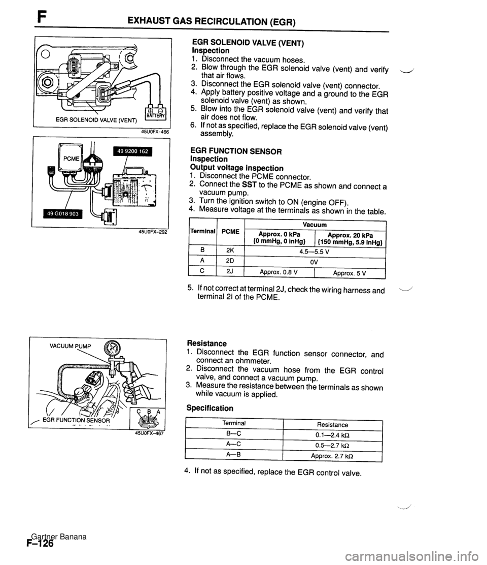
F EXHAUST GAS RECIRCULATION (EGR) VACUUM PUMP EGR SOLENOID VALVE (VENT) lnspection 1. Disconnect the vacuum hoses. 2. Blow through the EGR solenoid valve (vent) and verify u that air flows. 3. Disconnect the EGR solenoid valve (vent) connector. 4. Apply battery positive voltage and a ground to the EGR solenoid valve (vent) as shown. 5. Blow into the EGR solenoid valve (vent) and verify that air does not flow. 6. If not as specified, replace the EGR solenoid valve (vent) assembly. EGR FUNCTION SENSOR lnspection Output voltage inspection 1. Disconnect the PCME connector. 2. Connect the SST to the PCME as shown and connect a vacuum pump. 3. Turn the ignition switch to ON (engine OFF). 4. Measure voltage at the terminals as shown in the table. I I Vacuum I Terminal 5. If not correct at terminal 2J, check the wiring harness and 'i terminal 21 of the PCME. B A C Resistance 1. Disconnect the EGR function sensor connector, and connect an ohmmeter. 2. Disconnect the vacuum hose from the EGR control valve, and connect a vacuum pump. 3. Measure the resistance between the terminals as shown while vacuum is applied. PCME Specification 2K 2 D 2J Approx. 0 kPa {O mmHg, 0 inHg} 4. If not as specified, replace the EGR control valve. Approx. 20 kPa I150 mmHg, 5.9 inHg} 4.5--5.5 V OV Terminal LC A-C A-B Approx. 0.8 V Resistance 0.1-2.4 ki2 0.5-2.7 W1 Approx. 2.7 W1 Approx. 5 V Gartner Banana
Page 280 of 1708

FUEL EVAPORATIVE SYSTEM FUEL EVAPORATIVE SYSTEM DESCRIPTION The fuel evaporative system consists of the fuel vapor valve, the two-way check valve, the charcoal can- ister, the purge solenoid valve, the powertrain control module (engine), and the input devices. The amount of evaporative fumes introduced into the engine and burned is controlled by the solenoid valve in relation to the engine's operating conditions. To maintain the best engine performance, the solenoid valve is controlled by the powertrab control module (engine). THROTTLE 1-1 POSITION SENSOR I1 I I (IDLE SWITCH) 7 BAROMETIC ABSOLUTE PRESSURE SENSOR PARWNEUTRAL SWITCH (AT) MASS AIRFLOW SENSOR CRANKSHAFT POSITION SENSOR (SGT-SIGNAL) n - DUTY - LOW HIGH (ENGINE) CHARCOAL PURGE SOLENOID VALVE CANISTER HEATED OXYGEN SENSOR ENGINE COOLANT POWERTRAIN TEMPERATURE SENSOR CONTROL MODULE CHECK VALVE # 11 FUEL VAPOR VALVE Operation The purge solenoid valve is controlled by duty signals from the powertrain control module (engine) to per- form purging of the charcoal canister. Purging is done when these conditions are met: i/ 1. After warm-up. 2. Driving in gear. 3. Accelerator pedal depressed (idle switch OFF). 4. Heated oxygen sensor functioning normally. Gartner Banana
Page 281 of 1708
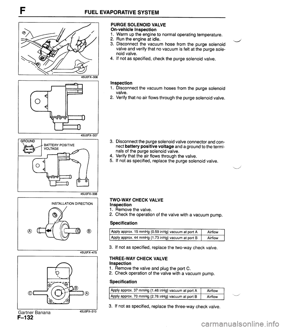
FUEL EVAPORATIVE SYSTEM I GROUND I PURGE SOLENOID VALVE On-vehicle lnspection 1. Warm up the engine to normal operating temperature. 2. Run the engine at idle. d 3. Disconnect the vacuum hose from the purge solenoid valve and verify that no vacuum is felt at the purge sole- noid valve. 4. If not as specified, check the purge solenoid valve. lnspection 1. Disconnect the vacuum hoses from the purge solenoid valve. 2. Verify that no air flows through the purge solenoid valve. 3. Disconnect the purge solenoid valve connector and con- nect battery positive voltage and a ground to the termi- nals of the purge solenoid valve. 4. Verify that the air flows through the valve. 5. If not as specified, replace the purge solenoid valve. TWO-WAY CHECK VALVE lnspection 1. Remove the valve. 2. Check the operation of the valve with a vacuum pump. INSTALLATION DIRECTION Specification I Apply approx. 15 mmHg i0.59 inHg} vacuum at port A 1 Airflow I 1 Agply apgrox. 44 mmH~ (1.73 inHd vacuum at Port 6 1 Airflow 1 3. If not as specified, replace the two-way check valve. THREE-WAY CHECK VALVE lnspection 1. Remove the valve and plug the port C. 2. Check operation of the valve with a vacuum pump. Specification 3. If not as specified, replace the three-way check valve. Apply approx. 37 mmHg {I -46 inHg} vacuum at port A Apply approx. 70 mmHg (2.76 inHg} vacuum at port I3 Airflow Airflow -d Gartner Banana
Page 285 of 1708
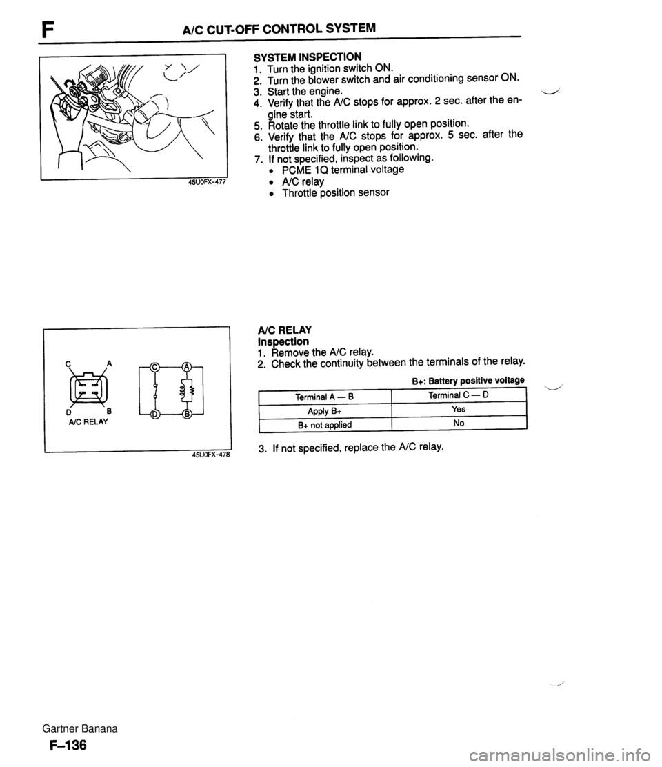
F A/C CUT-OFF CONTROL SYSTEM D B AIC RE LAY SYSTEM INSPECTION 1. Turn the ignition switch ON. 2. Turn the blower switch and air conditioning sensor ON. 3. Start the engine. d 4. Verify that the A/C stops for approx. 2 sec. after the en- gine start. 5. Rotate the throttle link to fully open position. 6. Verify that the A/C stops for approx. 5 sec. after the throttle link to fully open position. 7. If not specified, inspect as following. PCME 1Q terminal voltage A/C relay Throttle position sensor AIC RELAY Inspection 1. Remove the A/C relay. 2. Check the continuity between the terminals of the relay. 3. If not specified, replace the A/C relay. B+: Battery positive voltage Terminal A - B Apply B+ B+ not applied Terminal C - D Yes No Gartner Banana
Page 290 of 1708
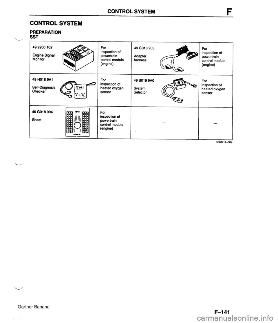
CONTROL SYSTEM CONTROL SYSTEM PREPARATION 49 9200 162 Engine Signal Monitor Self-Diagnosis Checker 49 GO1 8 904 Sheet For inspection of powertrain control module (engine) For inspection of heated oxygen sensor For inspection of powertrain control module (engine) 49 GO18 903 For inspection of Adapter powertrain harness control module 49 B019 9AO For inspection of System heated oxygen Selector sensor Gartner Banana
Page 293 of 1708
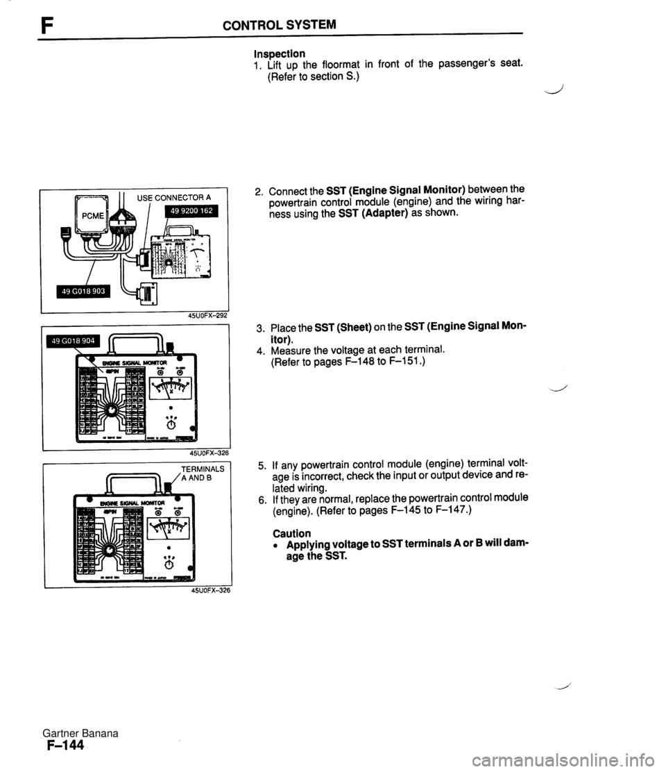
F CONTROL SYSTEM Inspection 1. Lift up the floormat in front of the passenger's seat. (Refer to section S.) ,i 1 USECONNECTORA TERMINALS /AANDB 2. Connect the SST (Engine Signal Monitor) between the powertrain control module (engine) and the wiring har- ness using the SST (Adapter) as shown. 3. Place the SST (Sheet) on the SST (Engine Signal Mon- itor). 4. Measure the voltage at each terminal. (Refer to pages F-148 to F-151.) 5. If any powertrain control module (engine) terminal volt- age is incorrect, check the input or output device and re- lated wiring. 6. If they are normal, replace the powertrain control module (engine). (Refer to pages F-145 to F-147.) Caution Applying voltage to SST terminals A or B will dam- age the SST. Gartner Banana
Page 294 of 1708
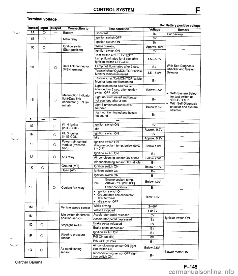
CONTROL SYSTEM F Terminal voltage B+: Battery positive voltage Test condition I Voltage I Remark - - - - - - - - - - - - - - - - - - Connection to Battery Constant Ignition switch OFF Main relay - B+ OV lgnition switch (Start position) For backup - Ignition switch ON While cranking Lamp illuminated for 3 sec. after 1 4.5-5.5V ianition switch OFF+ON 1 B+ Approx. 1 OV Ignition switch ON - - OV Data link connector (MEN terminal) Test switch at "SELF-TEST" .. Lamp not illuminated after 3 sec. Test switch at "02 MONITOR" at idle Monitor lam illuminated & 4.5-5.5v . . I Malfunction indicator IighVData link connector (FEN ter- minal) With Self-Diagnosis Checker and System Selector Test switch at "02 MONITOR" at idle Monitor lamp not illuminated Light illuminated and buzzer sounded for 3 sec. after ignition switch OFF-ON B+ tor tesiswitch at "SELF-TEST" With Self-Diagnosis checker and system selector Below 2.5V 1 Light illuminated and buzzer sounded 1 Below 2.5V I With System Selec- Light not illuminated and buzzer not sounded after 3 sec. I Light not illuminated and buzzer 1 n. 1 B+ not sound I D+ 1 - #I, 4 lgniter (in IG COIL) #2,3 Igniter (in IG COIL) Powertrain control module (transmis- sion) - Ignition switch ON Idle Ignition switch ON Idle lgnition switch ON (Engine coolant temp, below 60°C {I 40°F)) Ignition switch ON AtC relay Air conditioning sensor ON at idle Air conditioning sensor OFF at idle Ground (MT) - OV Approx. 0.2V OV Approx. 0.2V Below 1 .OV B+ Below 2.5V B+ - - - - , * Open (AT) - Ignition switch ON ( Below 1 .O V I Engine coolant temp. I Below .OV I ldle Above 97°C (206.6OF1 Ignition switch ON I I B+ Ignition switch ON Coolant fan relay B+ . - Other conditions lgnition switch On dround data link connector TEN terminal I Blow 1.0" I B+ Vehicle speed sensor ldle switch OFF While driving Vehicle sto~wed ldle switch (in throttle position sensor) 2-5V 1 or 7V . , Accelerator pedal released Accelerator ~edal de~ressed - Stoplight switch OV B+ Brake pedal released Brake ~edal deoressed lgnition switch ON Steering pressure sensor OV B+ I I - Ignition switch ON B+ - PIS ON (at idle) PIS OFF (at idle) Air conditioning sensor Air conditioning sensor ON (Igni- tion switch ON) Air conditioning sensor OFF (Igni- tion switch ON) OV B+ - Below 2.5V B+ Blower motor ON Gartner Banana