check engine MAZDA MX-5 1994 Workshop Manual
[x] Cancel search | Manufacturer: MAZDA, Model Year: 1994, Model line: MX-5, Model: MAZDA MX-5 1994Pages: 1708, PDF Size: 82.34 MB
Page 301 of 1708
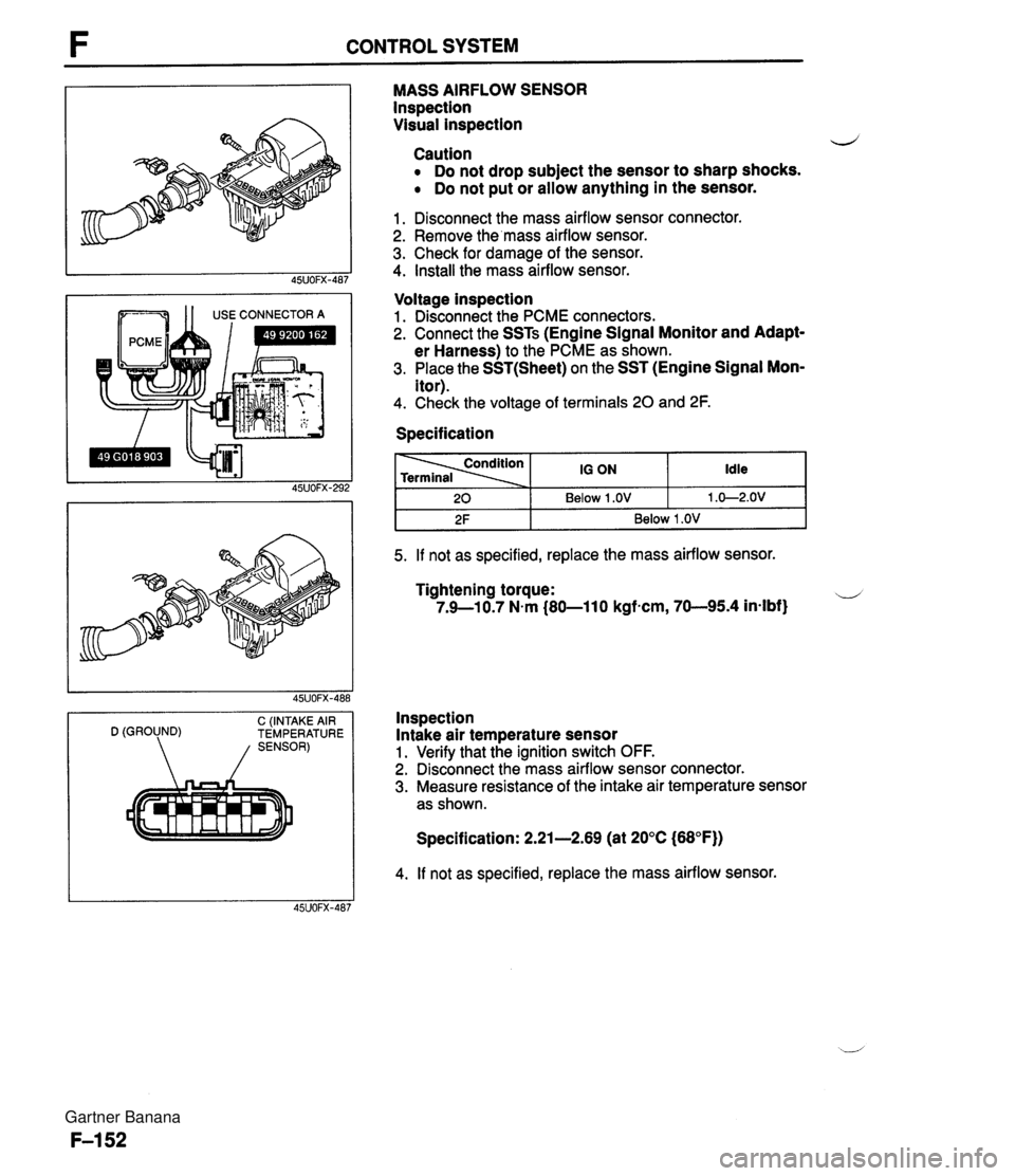
CONTROL SYSTEM --- 1 1 USE CONNECTOR A C (INTAKE AIR D (GROUND) TEMPERATURE MASS AIRFLOW SENSOR lnspection Visual inspection d Caution Do not drop subject the sensor to sharp shocks. Do not put or allow anything in the sensor. 1. Disconnect the mass airflow sensor connector. 2. Remove the'mass airflow sensor. 3. Check for damage of the sensor. 4. Install the mass airflow sensor. Voltage inspection 1. Disconnect the PCME connectors. 2. Connect the SSTs (Engine Signal Monitor and Adapt- er Harness) to the PCME as shown. 3. Place the SST(Sheet) on the SST (Engine Signal Mon- itor). 4. Check the voltage of terminals 20 and 2F. Specification I 2F I Below 1 .OV I 5. If not as specified, replace the mass airflow sensor. Idle 1 .O-2.OV 20 Tightening torque: u 7.9--10.7 N.m (80-11 0 kgfncm, 70-95.4 in-lbf} 10 ON Below 1 .OV Inspection Intake air temperature sensor 1. Verify that the ignition switch OFF. 2. Disconnect the mass airflow sensor connector. 3. Measure resistance of the intake air temperature sensor as shown. Specification: 2.21-2.69 (at 20°C (68°F)) 4. If not as specified, replace the mass airflow sensor. Gartner Banana
Page 302 of 1708
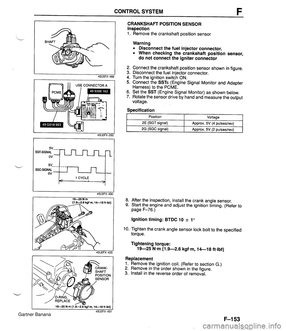
CONTROL SYSTEM 1 1 USE CONNECTOR A CRANKSHAFT POSITION SENSOR Inspection 1. Remove the crankshaft position sensor 5v- - - - SGGSIGNAL ov Warning Disconnect the fuel injector connector. When checking the crankshaft position sensor, do not connect the igniter connector - - - - I 1 CYCLE < > 2. Connect the crankshaft position sensor shown in figure. 3. Disconnect the fuel injector connector. 4. Turn the ignition switch ON. 5. Connect the SSTs (Engine Signal Monitor and Adapter Harness) to the PCME. 6. Set the SST (Engine Signal Monitor) as shown below. 7. Rotate the sensor drive by hand and measure the output voltage. Specification I 1 - Position - ~oltaael 8. After the inspection, install the crank angle sensor. 9. Start the engine and adjust the ignition timing. (Refer to page F-76.) 2E (SGT signal) 2G (SGC signal) Ignition timing: BTDC 10 2 1" Approx. 5V (4 pulseslrev) Approx. 5V (2 pulseslrev) 10. Tighten the crank angle sensor lock bolt to the specified torque. Tightening torque: 19-25 N-m (1 .+2.6 kgfem, 14-1 8 ftelbf} Replacement 1. Remove the ignition coil. (Refer to section G.) 2. Remove in the order shown in the figure. 3. Install in the reverse order of removal. Gartner Banana
Page 303 of 1708
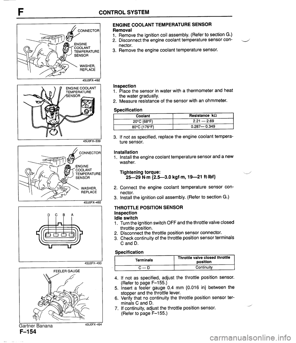
CONTROL SYSTEM TEMPERATURE NGlNE COOLANT EMPERATURE ENGINE COOLANT TEMPERATURE SENSOR Removal 1. Remove the ignition coil assembly. (Refer to section G.) 2. Disconnect the engine coolant temperature sensor con- 4 nector. 3. Remove the engine coolant temperature sensor. lnspection 1. Place the sensor in water with a thermometer and heat the water gradually. 2. Measure resistance of the sensor with an ohmmeter. 3. If not as specified, replace the engine coolant tempera- ture sensor. Specification DCBA Coolant 20°C {68"F) 80°C {I 76°F) FEELER GAUGE Resistance kR 2.21 - 2.69 0.287- 0.349 Installation 1. Install the engine coolant temperature sensor and a new washer. Tightening torque: -J 25-29 N.m (2.5-3.0 kgf-m, 19--21 ft-lbf) 2. Connect the engine coolant temperature sensor con- nector. 3. Install the ignition coil assembly. (Refer to section G.) THROTTLE POSITION SENSOR lnspection Idle switch 1. Turn the ignition switch OFF and the throttle valve closed throttle position. 2. Disconnect the throttle position sensor connector. 3. Check continuity of the throttle position sensor terminals C and D. I C-D I Continuity 4. If not as specified, adjust the throttle position sensor. (Refer to page F-155.) 5. Insert a feeler gauge 0.4 mm {0.016 in) between the stopper and the throttle lever. 6. Verify that no continuity the throttle position sensor ter- minals C and D. - 7. If continuity, adjust the throttle position sensor. (Refer to page F-155.) Specification Terminals Throttle valve closed throttle ~osition Gartner Banana
Page 305 of 1708

CONTROL SYSTEM SENSOR CONNECTOR EATED OXYGEN Specification Fully closed: 0.1-1.1 V Fully open: 3.14.5V (Verify that the voltage increase is directly d propotioned to the throttle valve opening angle.) 8. Tighten the attaching screws. Tightening torque: 1.6-2.3 N.m (16-24 kgfmm, 14-20 in-lbf} 9. If not adjusted, replace the throttle position sensor. 45UOFX-495 Replacement 1. Turn the ignition switch OFF. 2. Remove the throttle position sensor screws. 3. Remove the throttle position sensor . 4. Replace a new throttle position sensor and adjust it. (Refer to page F-155.) 5. Tighten the throttle position sensor screws. Tightening torque: 1.6-2.3 N.m (16-24 kgf-cm, 14-20 in-lbf} HEATED OXYGEN SENSOR Inspection On-vehicle 1. Warm-up the engine to normal operating temperature and run it at idle. 2. Disconnect the heated oxygen sensor connector. -.-' 3. Measure the voltage at terminal A. 4. If not as specified, check the intake air system, the fuel system and run the on-board diagnosis test. 5. If these system are OK, replace the heated oxygen sen- sor. Specification Heater 1. Disconnect the heated oxygen sensor connector. 2. Measure resistance between terminals C and D. Resistance: Approx. 13R (20°C (68°F)) Engine condition Terminal A 3. Replace the heater if not as specified. Increasing engine speed (V) 0.&1 .O Idle Below 1.0 Replacement 1. Disconnect the heated oxygen sensor connector. 2. Remove the heated oxygen sensor. 3. Install in the reverse order of removal. Decreasing engine speed (V) 0-0.4 Tightening torque: 3049 N-m (3.0-5.0 kgf-m, 22-36 ftlbf) Gartner Banana
Page 307 of 1708

CONTROL SYSTEM Replacement Replace the neutral switch as shown in the figure. STEERING PRESSURE SENSOR Inspection 1. Disconnect the steering pressure sensor connector. 2. Connect an ohmmeter to the switch. 3. Start the engine and let it idle. Check continuity of the switch while turning the steering wheel. PIS 1 Continuity Turnina Yes " I t ~ot turning I NO 4. If not as specified, replace the steering pressure sensor. Replacement Replace the steering pressure sensor as shown in the figure. Gartner Banana
Page 311 of 1708

TROUBLESHOOTING GUIDE TROUBLESHOOTING GUIDE Problem Will not crank Cranks slowly Discharged battery Misfire G-5 Will not crank I Will not crank I Check 1 1 , YES, Check if engine cranks with fully charged battery Check charging system (Refer to page G-7) I NO Check ignition switch (Refer to section T), starter interlock switch (Refer to page G-28) and parWneutral switch (Refer to section K) 45uOOx-OC - Check 1 Check if click is heard from starter magnetic switch when ignition is turned to START Cranks slowly Check starting system (Refer to page G-21) Crank slowly Check 1 Check charging system (Refer to page G-7) I NO ---- Check starting system (Refer to page G-21) Check 1 Gartner Banana
Page 314 of 1708

CHARGING SYSTEM G TROUBLESHOOTING Check 1 Check if battery p Check battery (Refer to page G-8) J Check 2 I. Turn ignition switch ON Check wire harness 2. Check if voltage exists at each terminal of alternator Check 3 YES 1. Start engine Check alternator (Refer to page G-10) 2. Check if alternator warning light goes off I YES Check if drive belt t Adjust or replace drive belt (Refer to page G-14) 1 YES I Check for dark current (Refer to page G-3) I Check 1 BATTERY r"; Check 3 I ALTERNATOR WARNING LIGHT Check 2 B+: Battery positive voltage I I I B 1 Approx. 12V 1 Approx. 12V I B+ ON ON (Idle) L S 45UOGX-006 OV Approx. 12V Approx. 1V Approx. 12V B+ B+ Gartner Banana
Page 316 of 1708

CHARGING SYSTEM G Battery discharge test capable of reading 0.01V Quick charge for 30 min- utes and recheck voltage elo ow 12.4V Above 12.4V I Replace battery el c Apply test load (see test load chart) to the battery using a battery load tester Record battery positive voltage at the end of 15 seconds; is voltage more than specifica- tion? I Measure open circuit voltage of battery 1 Replace battery I I Below 12.4V Abov'e 12.4V Test load I Battew I Load (A1 I Battery posltive voltage with load I Charge battery ( I Battery OK I Terminal and cable 1. Clean and tighten the battery terminals and cables. 2. Coat the terminals with arease. 3. Inspect for corroded or 6ayed battery cables. 4. Check the rubber protector on the positive terminal for proper coverage. Recharging Warning Before performing maintenance or recharging the battery, turn off all accessories and stop the engine. The negative battery cable must be removed first and installed last. Battery S46A24L(S) Caution Do not remove vent caps. Follow carefully the instructions of the battery charger to prevent overcharging. u Do not recharging over 30 minutes to prevent damage the battery. Slow charge (A) Under 3 - -- Quick charge (A) Max. 20 Gartner Banana
Page 320 of 1708
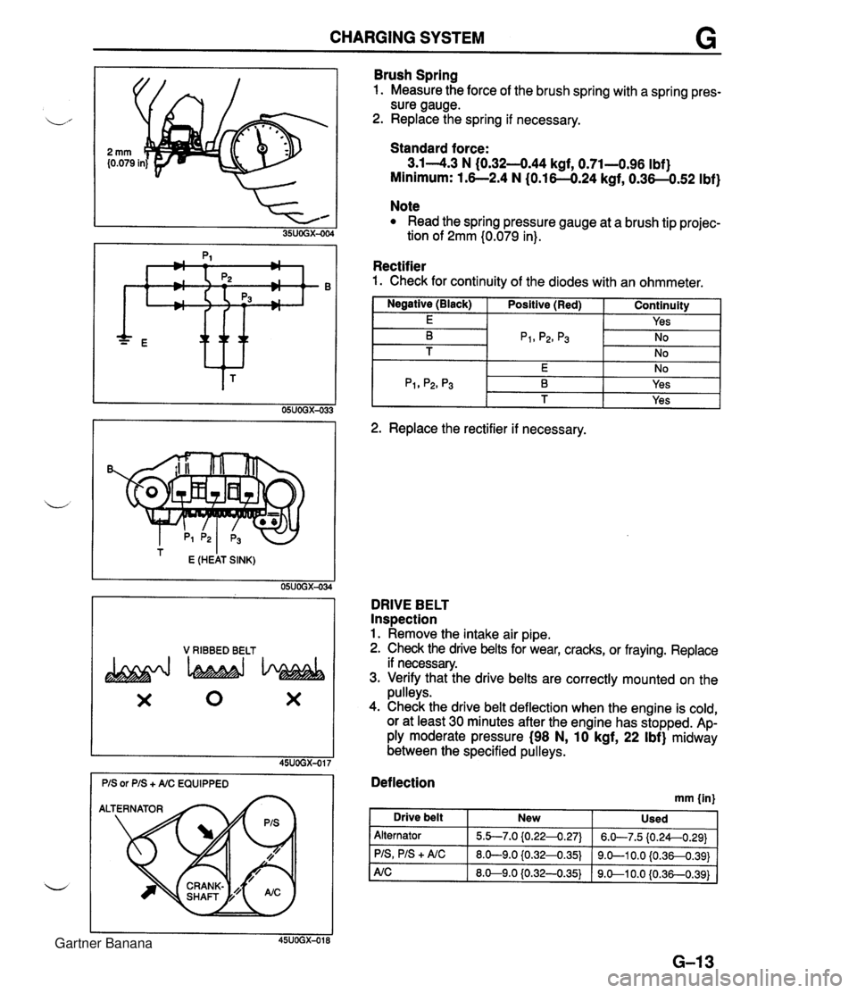
CHARGING SYSTEM G * ttt I E (HEAT SINK) 05UOGX-034 V RIBBED BELT X 0 X Brush Spring 1. Measure the force of the brush spring with a spring pres- sure gauge. 2. Replace the spring if necessary. Standard force: 3.14.3 N (0.32-444 kgf, 0.71-0.96 Ibf) Minimum: 1.6--2.4 N (0.16-0.24 kgf, 0.36-0.52 Ibf) Note Read the spring pressure gauge at a brush tip projec- tion of 2mm (0.079 in). Rectifier 1. Check for continuity of the diodes with an ohmmeter. I Negative (Black) I Positive (Red) I Continuity 1 I E I I Yes I -- 2. Replace the rectifier if necessary. DRIVE BELT Inspection 1. Remove the intake air pipe. 2. Check the drive belts for wear, cracks, or fraying. Replace if necessary. 3. Verify that the drive belts are correctly mounted on the pulleys. 4. Check the drive belt deflection when the engine is cold, or at least 30 minutes after the engine has stopped. Ap- ply moderate pressure (98 N, 10 kgf, 22 Ibf) midway between the specified pulleys. Deflection mm {in) I Drive belt New Used Alternator PIS, PIS + A/C 5.b7.0 {0.224.27) 8.0-9.0 iO.32-0.35) 6.W7.5 (0.24--0.29) 9.0-1 0.0 {0.36-0.391 Gartner Banana
Page 321 of 1708
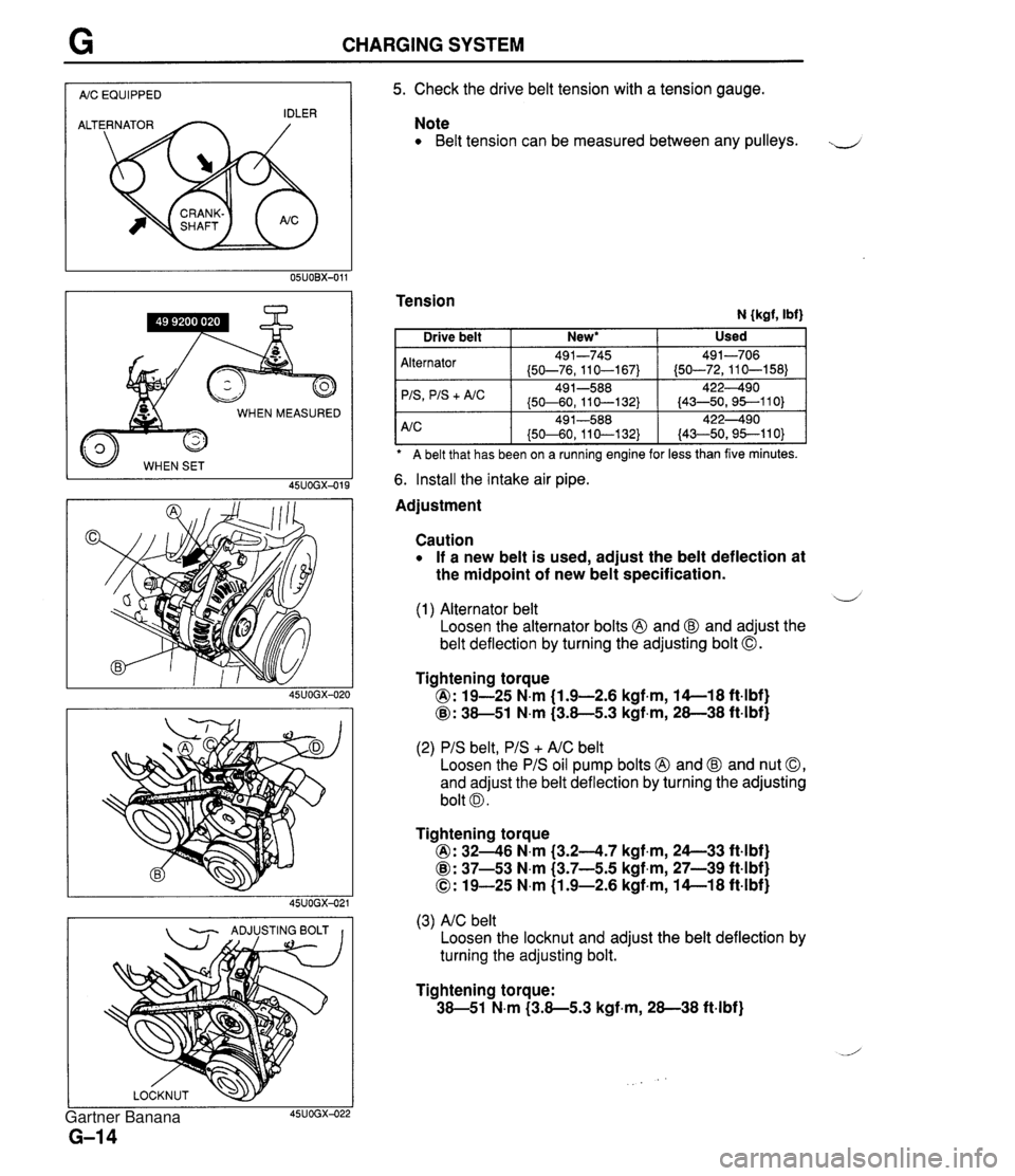
CHARGING SYSTEM I AIC EQUIPPED I WHEN MEASURED 45UOGX-015 - ADJUSTING BOLT I I 5. Check the drive belt tension with a tension gauge. Note Belt tension can be measured between any pulleys. J Tension N {kgf, Ibf) A belt that has been on a ruining engine for less than five minutes. Alternator 'IS
+ A/C 6. Install the intake air pipe. Used Drive belt Adjustment New* I Caution If a new belt is used, adjust the belt deflection at the midpoint of new belt specification. 491-745 (50-76,110-167) 49 1-588 (50-60, 11 0-1 32) d (1) Alternator belt Loosen the alternator bolts @ and @ and adjust the belt deflection by turning the adjusting bolt 0. 491-706 (50-72,110-158) 422490 (43-50,95--110) Tightening torque @: 19-25 N.m (1.9-2.6 kgf.m, 14-1 8 ft4bf) @: 38-51 N.m (3.8-5.3 kgf,m, 28-38 ft-lbf) (2) PIS belt, PIS + AIC belt Loosen the PIS oil pump bolts @ and @ and nut 0, and adjust the belt deflection by turning the adjusting bolt 0. Tightening torque @: 3246 N.m (3.24.7 kgf.m, 24--33 ft4bf) @: 37-53 N.m (3.7-5.5 kgf,m, 27-39 ft-lbf) 0: 19-25 N.m (1.9-2.6 kgf-m, 14-1 8 ft-lbf) (3) AIC belt Loosen the locknut and adjust the belt deflection by turning the adjusting bolt. Tightening torque: 38-51 N.m (3.8-5.3 kgf-m, 28-38 ft-lbf) Gartner Banana