check engine MAZDA MX-5 1994 Workshop Manual
[x] Cancel search | Manufacturer: MAZDA, Model Year: 1994, Model line: MX-5, Model: MAZDA MX-5 1994Pages: 1708, PDF Size: 82.34 MB
Page 1035 of 1708

T SRS AIR BAG SYSTEM Possible cause ij Defective diagnostic module Defective wiring harness Defective S-sensor Step 1 Carry out "Before Servicing" procedure under GEN- ERAL PROCEDURES, page T-1 60. Service Code 12 Flowchart No.3 Step 2 Check the ENGINE fuse. Fuse Action I Symptom Step 3 1. Disconnect the diagnostic module connector. 2. Connect the negative battery cable. 3. Measure the voltage at terminal 1 L (WIG) of the diagnos- OK Burnt tic module connector. Go to Step 3 Go to Step 4 B+: Battery positive voltage - Other Repair wiring harness iEGI INJ fuss-Diaanostic module1 I Voltage B+ -- ~ Action Replace diagnostic module (Refer to page T-208) I NO Replace diagnostic module (Refer to Daae T-2081 Step 4 1. Disconnect the diagnostic module connector. 2. Check for continuity between terminal 1 H (GIB) of the diagnostic module connector and ground. Step 5 1. Disconnect the orange and blue S-sensor connectors. 2. Check for continuity between terminal 2C (G) of the diag- nostic module connector and ground. 1 Continuity Action 1 Continuity Yes Action Go to Step 5 Yes No Replace wiring harness Go to Step 6 L Gartner Banana
Page 1069 of 1708

TROUBLESHOOTING u 7- Symptom: Magnetic clutch does not operate I Normal operation of magnetic clutch The PCME controls the operation of the condenser fan and magnetic clutch, depending on engine load. (Refer to section F.) The magnetic clutch is supplied with battery positive voltage as follows: 1. The ACS and fan switch are turned on. 2. The PCME receives a signal that the ACS and fan switch are on and creates a ground circuit. 3. The A/C relay is magnetized and the contact is closed. 4. Battery positive voltage is applied to the magnetic clutch and the clutch locks. WIPER 20A AD FAN 20A FUSE BLOCK MAIN FUSE BLOCK Step 1 1. Check the following fuses. I Fuse I Amperage I Location I I I . - I WIPER I 20A 1 In fuse block I I AD FAN I 20A 1 In main fuse block I 2. If the fuses are OK, go to Step 2. 3. If a fuse is burned, check for a short circuit in the harness before replacing it. Step 2 1. Run the engine at idle. 2. Turn on the ACS and fan switch. 3. Measure the voltage at the A terminal wire of the mag- netic clutch connector. B+: Battery positive voltage I Terminal I Voltage I Action 1 Step 3 1. Start the engine. 2. Turn on the fan switch and ACS. 3. Measure the voltage at terminal C and A of the A/C relay connector. B+: Batterv positive voltaae - -- A 1 Terminal I V0lta0e 1 Action I I C I Other I Repair wiring harness (AD FAN 20A fuse - AIC relay) I B+ Other I 1. -. B+ I GO to step 4 Replace magnetic clutch Go to Step 3 I A 1 Other I Repair wiring harness (WIPER 20A fuse - AIC relay) I Gartner Banana
Page 1071 of 1708

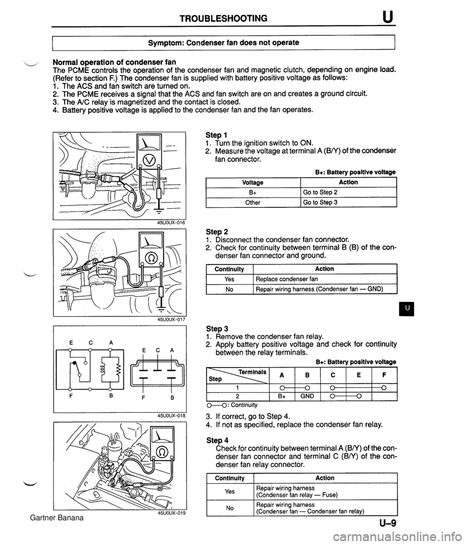
TROUBLESHOOTING u Symptom: Condenser fan does not operate Normal operation of condenser fan The PCME controls the operation of the condenser fan and magnetic clutch, depending on engine load. (Refer to section F.) The condenser fan is supplied with battery positive voltage as follows: 1. The ACS and fan switch are turned on. 2. The PCME receives a signal that the ACS and fan switch are on and creates a ground circuit. 3. The A/C relay is magnetized and the contact is closed. 4. Battery positive voltage is applied to the condenser fan and the fan operates. Step 1 1. Turn the ignition switch to ON. 2. Measure the voltage at terminal A (B/Y) of the condenser fan connector. B+: Battery positive voltage Step 2 1. Disconnect the condenser fan connector. 2. Check for continuity between terminal B (B) of the con- denser fan connector and ground. Voltage B+ Other I GO to step 3 Action Go to Step 2 I continuity I Action I Step 3 1. Remove the condenser fan relay. 2. Apply battery positive voltage and check for continuity between the relay terminals. B+: Battery positive voltage Yes No Replace condenser fan Repair wiring harness (Condenser fan - GND) M: Continuity - - - 3. If correct, go to Step 4. 4. If not as specified, replace the condenser fan relay. 1 0 2 B+ Step 4 Check for continuity between terminal A (BN) of the con- denser fan connector and terminal C (BN) of the con- denser fan relay connector. I Continuity I Action 1 Repair wiring harness (Condenser fan relay - Fuse) B 0 GND I Repair wiring harness (Condenser fan - Condenser fan relay) I C 0 0 E 0 F 0 Gartner Banana
Page 1072 of 1708

TROUBLESHOOTING I ltem 1 Symptom Symptom: lnsuff icient cooling No cooling Intermittent cooling Ill Bubbles present in sight glass u Immediately after air conditioner turned off, refrigerant in sight glass stavs clear I. When air conditioner turned off, re- frigerant foams, and then sight glass becomes clear No bubbles present in sight glass Step 1 Checking refrigerant charge 1. Run the engine at a fast idle. 2. Operate the air conditioner at maximum cooling for a few minutes. 3. Observe the sight glass to determine the amount of re- frigerant and the related action as shown below. Amount of refrigerant Action Insufficient refrigerant Too much or proper amount of refrig- erant Too much refrigerant Step 2 Checking refrigerant pressure 1. Connect the manifold gauge set. 2. Operate the engine at 1,500 rpm and set the air condi- tioner to maximum cooling. 3. Measure the refrigerant pressure. 1 Proper amount of refrigerant Normal pressure Low-pressure side: 0.1 5-4.24 MPa (1.5--2.5 kgf/cm2, 22--35 psi) High-pressure side: 1.38-1.56 MPa (1 4.0-1 6.0 kgf/cm2, 200-227 psi) Check refrigerant pressure, go to Step 2 Turn air conditioner off, and watch bubbles (Refer to Items 3 and 4) Check refrigerant pressure, go to Step 2 Refrigerant amount normal 4. If the pressures not as specified, refer to the chart on the next page and check the system. ,d Gartner Banana
Page 1076 of 1708

u TROUBLESHOOTING Case 6: Expansion valve stuck open Measured pressure Low-pressure side: 0.30-0.39 MPa {3.0-4.0 kgf/cm2, 43-56 psi) High-pressure side: 1.97-2.45 MPa (20.0-25.0 kgf/cm2, 285-355 psi) Condition Insufficient cooling. CAUSE ACTION 7 m EXPANSION REPLACE / VALWEiUCK I *I EXPANSION VALVE Case 7: Faulty AIC compressor Measured pressure 1. Check whether there is frost or heavy dew on the suction pipe (between cooling unit and AIC compressor). 2. If neither is found, refer to "Excessive refrigerant or insuf- ficient condenser cooling"; page U-12. 3. If either is found, replace the expansion valve. (Refer to page U-31.) LOW-pressure side: 0.4-0.5 MPa (4.0-6.0 kgf/cm2, 57-85 psi) High-pressure side: 0.69-0.98 MPa (7.0-10.0 kgflcm2, 100-1 42 psi) Condition No cooling. I 1 Remedy CAUSE ACTION MOISTURE IN 1. Run ihe engine at a first idle. 2. Verify that the magnetic clutch is on when the ACS and fan switch are on. 3. If the magnetic clutch remains off, refer to "Magnetic clutch does not operate"; page U-7. Gartner Banana
Page 1088 of 1708

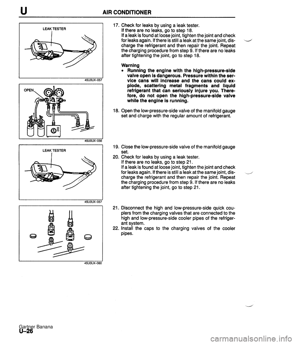
u AIR CONDITIONER LEAK TESTER I LEAK TESTER I 17. Check for leaks by using a leak tester. If there are no leaks, go to step 18. If a leak is found at loose joint, tighten the joint and check for leaks again. If there is still a leak at the same joint, dis- 4 charge the refrigerant and then repair the joint. Repeat the charging procedure from step 9. If there are no leaks after tightening the joint, go to step 18. Warning Running the engine with the high-pressure-side valve open is dangerous. Pressure within the ser- vice cans will increase and the cans could ex- plode, scattering metal fragments and liquid refrigerant that can seriously injure you. There- fore, do not open the high-pressure-side valve while the engine is running. 18. Open the low-pressure-side valve of the manifold gauge set and charge with the regular amount of refrigerant. 19. Close the low-pressure-side valve of the manifold gauge set. 20. Check for leaks by using a leak tester. If there are no leaks, go to step 21. If a leak is found at loose joint, tighten the joint and check for leaks again. If there is still a leak at the same joint, dis- charge the refrigerant and then repair the joint. Repeat the charging procedure from step 9. If there are no leaks after tightening the joint, go to step 21. 21. Disconnect the high and low-pressure-side quick cou- plers from the charging valves that are connected to the high and low-pressure-side cooler pipes of the refriger- ant system. 22. Install the caps to the charging valves of the cooler pipes. Gartner Banana
Page 1091 of 1708

AIR CONDITIONER u "C "F 26 24 22 20 18 16 14 12 10 40 59 60 70 RELATIVE HUMIDITY I ltem I Symptom 10. Read the dry thermometer at the air outlet, and calculate the difference between the inlet dry bulb and outlet dry bulb temperatures. 11. Verify that the intersection of the relative humidity and temperature difference is in the shaded zone. Checking Refrigerant Charge 1. Run the engine at a fast idle. 2. Operate the air conditioner at maximum cooling for a few minutes. 3. Determine the amount of refrigerant as shown below by observing the sight glass. 1 Bubbles present in sight glass 2 No bubbles present in sight glass Immediately after air conditioner turned OFF, refrigerant in sight glass stavs clear 141 When air conditioner turned OFF, re- frigerant foams, and then sight glass becomes clear -- Amount of refrigerant Insufficient refrigerant Action Check refrigerant pressure -- Too much or proper amount of refrig- erant Too much refrigerant Checking Refrigerant Pressure 1. Connect the manifold gauge set. (Refer to page U-25.) 2. Operate the engine at 1,500 rpm and set the air condi- tioner to maximum cooling. 3. Measure the low- and high-pressure sides. Turn air conditioner OFF, and watch bubbles (Refer to Items 3 and 4) Check refrigerant pressure Proper amount of refrigerant Stabilized condition Low-pressure side: 0.15-4.24 MPa {I .5--2.5 kgf/cm2, 22-35 psi) High-pressure side: 1.38-1.56 MPa (1 4.61 6.0 kgflcm*, 200-227 psi) Refrigerant amount normal Gartner Banana
Page 1094 of 1708

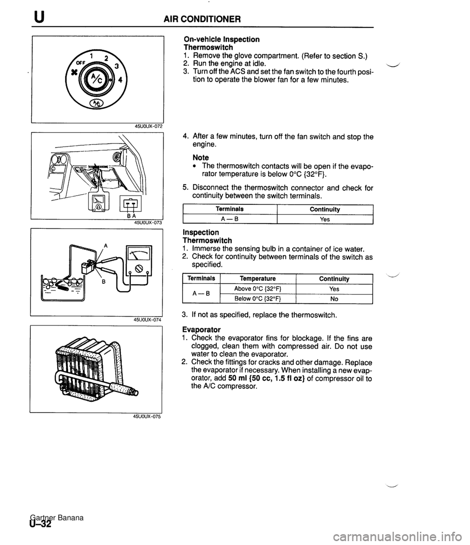
AIR CONDITIONER On-vehicle Inspection Thermoswitch 1. Remove the glove compartment. (Refer to section S.) 2. Run the engine at idle. u 3. Turn off the ACS and set the fan switch to the fourth posi- tion to operate the blower fan for a few minutes. 4. After a few minutes, turn off the fan switch and stop the engine. Note The thermoswitch contacts will be open if the evapo- rator temperature is below 0°C (32°F). 5. Disconnect the thermoswitch connector and check for continuity between the switch terminals. I Terminals I Continuity I I A-B I Yes I - -- Inspection Thermoswitch 1. Immerse the sensing bulb in a container of ice water. 2. Check for continuity between terminals of the switch as specified. 3. If not as specified, replace the thermoswitch. Continuity ( Terminals I Temperature A-B Evaporator 1. Check the evaporator fins for blockage. If the fins are clogged, clean them with compressed air. Do not use water to clean the evaporator. 2. Check the fittings for cracks and other damage. Replace the evaporator if necessary. When installing a new evap- orator, add 50 ml (50 cc, 1.5 fl oz) of compressor oil to the A/C compressor. d Above 0°C {32OFj Below 0°C (32°F) Yes No Gartner Banana
Page 1113 of 1708

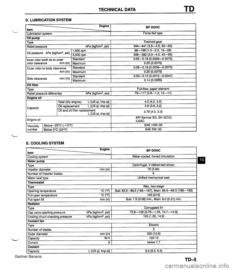
TECHNICAL DATA D. LUBRICATION SYSTEM - Engine ltem BP DOHC - -. Lubrication system Force-fed type E. COOLING SYSTEM Trochoid gear 344-41 I3.5--4.5,s-31 9&l96 {I .&2.0, 15--28) 295-392 {3.0-4.0,43-56) 0.02-0.1 8 {0.000&0.0070) 0.20 {0.0079) 0.09-0.18 (0.0036-0.0070) 0.20 {0.0079) 0.03-0.1 2 {0.0012-0.0047) 0.14 (0.0055) TY pe Relief pressure kPa {kgf/cm2, psi) Oil pressure kPa {kgf/cm2, psi) Inner rotor tooth tip to outer rotor clearance mm {in) Outer rotor to body clearance mm {in) Side clearance mm {in) Water seal type I Unified mechanical seal Thermostat 1,000 rpm 3,000 rpm Standard Maximum Standard Maximum Standard Maximum Oil filter Engine ltem - - Cooling system . . Impeller diameter mm {in) Number of impeller blades Type Relief pressure differential kPa {kgf/cm2, psi) BP DOHC Water-cooled, forced circulation - 75 i2.95) 6 Full-flow, paper element 74-1 17 {0.&1.2, 12-1 7) TY pe . ., . . . - Radiator I Water pump Wax, two-stage v. . . Full-open temperature "c {OF) Full-open lift mm {in) Engine oil TVD~ O~enina tem~erature "C con I Sub: 83.5-86.5 U83-187). Main: 86.5-89.5 (1 88-1 931 100 (21 2) Sub: 1.5 (0.06) min., Main: 8.0 (0.31) min. -. . - . . Cooling circuit checking pressure kPa {kgflcmz, psi) I 103 {I .05, 14.9) I Centrifugal, V-ribbed belt driven TY pe I Coolant fan I 4.0 (4.2, 3.5) 3.6 {3.8,3.2) 3.75 (4.0, 3.3) API Service SG, SH (ECII) ILSAC Capacity Corrugated fin viscosity Above -25°C (-1 3°F) SAE 1 OW-30 number Below 0°C {3Z°F) SAE 5W-30 Total (dry engine) L {US qt, Imp qt) Oil replacement L {US qt, Imp qt) Oil and oil filter replacement L {US qt, Imp qtl Cap valve o~enina pressure kPa {krrf/cm2, psi} 1 73.6--102 {0.75--1.05, 10.7-14.91 Capacity W-V I 120-1 2 Current A 1 below 7.7 Engine oil Type Number of blades Outer diameter mm {in) Coolant Capacity L {US qt, Imp qt) I 6.0 {6.3,5.3) Electric 5 320 (1 2.61 Gartner Banana
Page 1124 of 1708

SPECIAL TOOLS .................... GENERAL INFORMATION ST- 2 ..................................... ENGINE ST- 3 CLUTCH AND MANUAL TRANSMISSION ...... ST- 4 ................. AUTOMATIC TRANSMISSION ST- 5 .............................. DIFFERENTIAL ST- 6 ................... FRONT AND REAR AXLES ST- 7 ......................... STEERING SYSTEM ST- 7 .......................... BRAKING SYSTEM ST- 9 ........... FRONT AND REAR SUSPENSIONS ST-1 0 CHECKERS AND OTHER EQUIPMENT ........ ST-10 4SUOTX-001 Gartner Banana