engine MAZDA MX-5 1994 Workshop Manual
[x] Cancel search | Manufacturer: MAZDA, Model Year: 1994, Model line: MX-5, Model: MAZDA MX-5 1994Pages: 1708, PDF Size: 82.34 MB
Page 235 of 1708
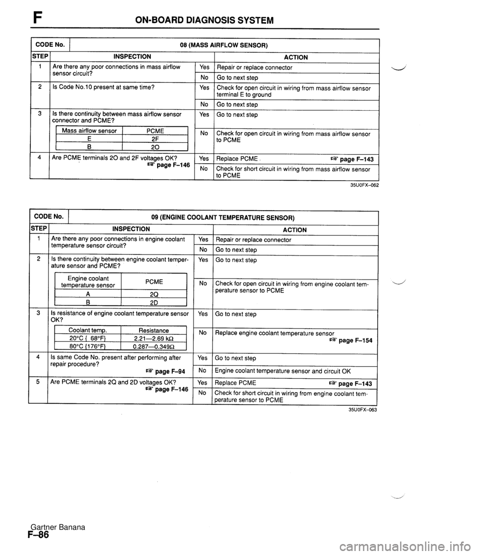
F ON-BOARD DIAGNOSIS SYSTEM CODE No. ACTION Yes I Repair or replace connector 08 (MASS AIRFLOW SENSOR) iTEP 1 No I Go to next step INSPECTION Are there any poor connections in mass airflow sensor circuit? Yes 2 Check for open circuit in wiring from mass airflow sensor terminal E to wound Is Code No.10 present at same time? No ( Go to next step 1 Is there continuity between mass airflow sensor connector and PCME? Yes Go to next step Mass airflow sensor E B I Yes I Replace PCME . us page F-143 PCME 2F 20 No Check for short circuit in wiring from mass airflow sensor to PCME Are PCME terminals 20 and 2F voltages OK? page F-146 Check for open circuit in wiring from mass airflow sensor to PCME CODE No. ACTION 09 (ENGINE COOLANT TEMPERATURE SENSOR) STEP 1 Repair or replace connector Go to next step INSPECTION Are there any poor connections in engine coolant temperature sensor circuit? Go to next step Yes - No 2 Engine coolant temperature sensor PCME Check for open circuit in wiring from engine coolant tem- perature sensor to PCME Is there continuity between engine coolant temper- ature sensor and PCME? 4 Is resistance of engine coolant temperature sensor 1 /om I yes Yes Go to next step Coolant temp. Resistance 1 I 20°C ( 68°F) 1 2.21-2.69 kR Replace engine coolant temperature sensor page F-154 Is same Code No. present after performing after repair procedure? page F-94 Go to next step Engine coolant temperature sensor and circuit OK Are PCME terminals 2Q and 2D voltages OK? page F-146 Re~lace PCME ~aae F-143 Check for short circuit in wiring from engine coolant tem- perature sensor to PCME Gartner Banana
Page 236 of 1708
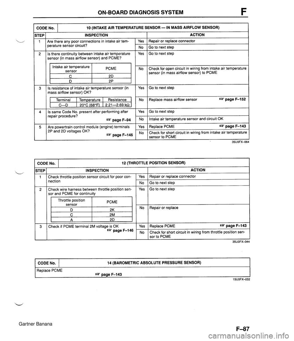
ON-BOARD DIAGNOSIS SYSTEM I CODE No. I -- -- 10 (INTAKE AIR TEMPERATURE SENSOR - IN MASS AIRFLOW SENSOR) INSPECTION Are there any poor connections in intake air tem- Yes perature sensor circuit? No Is there continuity between intake air temperature Yes sensor (in mass airflow sensor) and PCME? Intake air temperature sensor PCME I D 2 P Is resistance of intake air temperature sensor (in Yes mass airflow sensor) OK? Terminal I Temperature I Resistance No C-D I 20°C {68"F) 1 2.21-2.69 kR Is same Code No. present after performing after Yes repair procedure? page F-94 No Are powertrain control module (engine) terminals 2P and 2D voltages OK? @= page F-146 ACTION Repair or replace connector Go to next step Go to next step Check for open circuit in wiring from intake air temperature sensor (in mass airflow sensor) to PCME Go to next step Replace mass airflow sensor @= page F-152 -- Go to next step Intake air temperature sensor and circuit OK Replace PCME IS= page F-143 Check for short circuit in wiring from intake air temperature sensor to PCME CODE No. 12 (THROTTLE POSITION SENSOR) I Check throttle position sensor circuit for poor con- nection Throttle position sensor PCME D 2K 2 Repair or replace STEP 1 INSPECTION Yes No ACTION Repair or replace connector Go to next step Check wire harness between throttle position sen- sor and PCME for continuity 3 Replace PCME IS= page F-143 15UOFX-032 Yes CODE No. Go to next step 35UOFX-04 Check if PCME terminal 2M voltage is OK page F-146 14 (BAROMETRIC ABSOLUTE PRESSURE SENSOR) Yes No Replace PCME I@= page F-143 Check for short circuit in wiring from throttle position sen- sor to PCME Gartner Banana
Page 237 of 1708
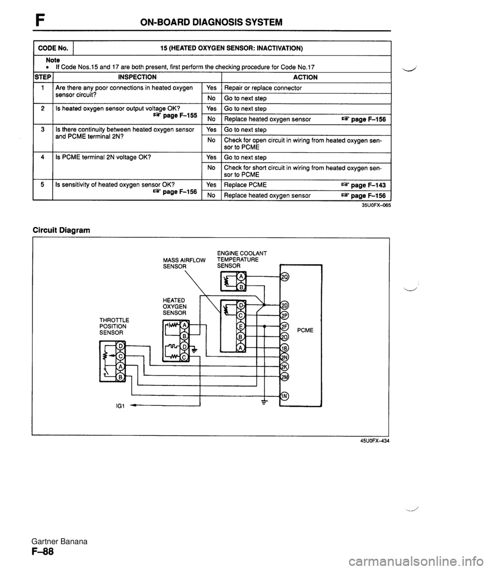
F ON-BOARD DIAGNOSIS SYSTEM CODE No. 15 (HEATED OXYGEN SENSOR: INACTIVATION) 111 Are there any poor connections in heated oxygen sensor circuit? Note a If Code Nos.15 and 17 are both present, first perform the checking procedure for Code No.17 STEP 1 INSPECTION I ACTION 2 3 Circuit Diagram I Yes No 4 5 ENGINE COOLANT MASS AIRFLOW TEMPERATURE SENSOR SENSOR ~ Repair or replace connector Go to next steD Is heated oxygen sensor output voltage OK? page F-155 Is there continuity between heated oxygen sensor and PCME terminal 2N? THROTTLE POSITION SENSOR 35UOFX-065 Is PCME terminal 2N voltage OK? Is sensitivity of heated oxygen sensor OK? * page F-156 PCME Yes No Yes No Go to next step Replace heated oxygen sensor r@ page F-156 Go to next step Check for open circuit in wiring from heated oxygen sen- sor to PCME Yes No Yes No Go to next step Check for short circuit in wiring from heated oxygen sen- sor to PCME Replace PCME aPi. page F-143 Replace heated oxygen sensor r@ page F-156 Gartner Banana
Page 239 of 1708

F ON-BOARD DIAGNOSIS SYSTEM CODE No. 17 (HEATED OXYGEN SENSOR: INVERSION) I Circuit Diagram INSPECTION Warm up engine and run it at 2,500-3,000 rpm for 3 min. HEATED OXYGEN SENSOR ACTION Does monitor lamp of Self-Diagnosis Checker illu- minate at idle? Are spark plugs clean? Is heated oxygen sensor voltage OK? * page F-156 Is same Code No. present after performing after repair procedure? ESI= page F-90 Is there continuity between heated oxygen sensor and PCME terminal 2N? Is PCME terminal 2N voltage OK? * page F-146 PCME Yes No Yes No Yes No Yes No Yes No Yes No Go to next step Check for air leak in vacuum hoses or emission compo- nents Check for contaminated heated oxygen sensor Check for insufficient fuel injection Go to next step Clean or replace spark plugs Go to next step Replace heated oxygen sensor page F-156 Go to next step Check for short circuit in wiring from heated oxygen sen- sor to PCME terminal 2N Go to next step Check for open circuit in wiring from heated oxygen sen- sor to PCME Replace PCME page F-143 Check for short circuit in wiring from heated oxygen sen- sor to PCME Gartner Banana
Page 243 of 1708
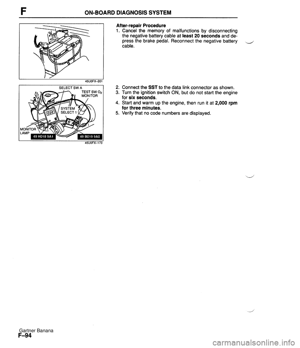
ON-BOARD DIAGNOSIS SYSTEM SELECT SW A Af ter-repair Procedure 1. Cancel the memory of malfunctions by disconnecting the negative battery cable at least 20 seconds and de- press the brake pedal. Reconnect the negative battery cable. 2. Connect the SST to the data link connector as shown. 3. Turn the ignition switch ON, but do not start the engine for six seconds. 4. Start and warm up the engine, then run it at 2,000 rpm for three minutes. 5. Verify that no code numbers are displayed. Gartner Banana
Page 244 of 1708
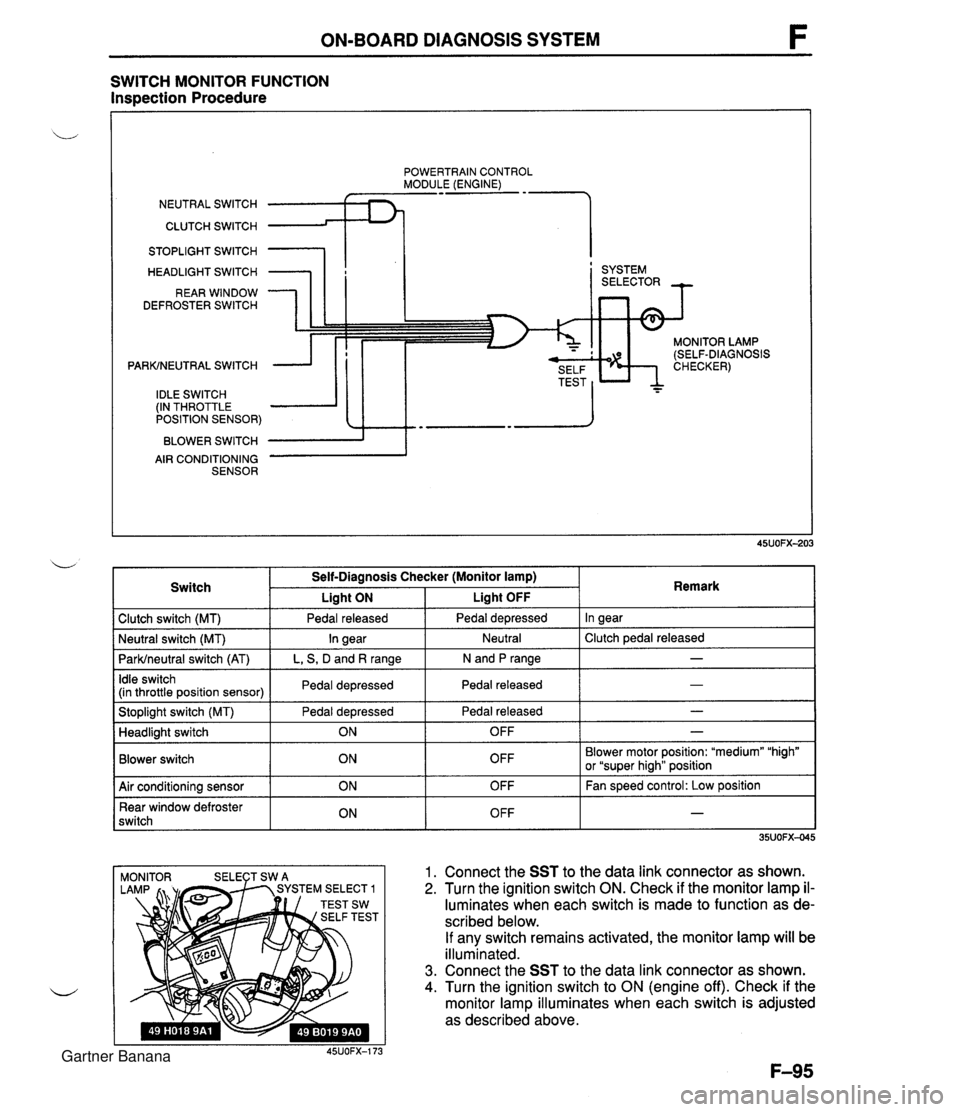
ON-BOARD DIAGNOSIS SYSTEM SWITCH MONITOR FUNCTION Inspection Procedure POWERTRAIN CONTROL MODULE (ENGINE) NEUTRAL SWITCH CLUTCH SWITCH 1 STOPLIGHT SWITCH HEADLIGHT SWITCH REAR WINDOW DEFROSTER SWITCH PARKINEUTRAL SWITCH IDLE SWITCH (IN THROTTLE POSITION SENSOR) BLOWER SWITCH AIR CONDITIONING SENSOR I ' SYSTEM MONITOR LAMP (SELF-DIAGNOSIS 1 Clutch switch (MT) 1 Pedal released I Pedal depressed I In gear I Switch Self-Diagnosis Checker (Monitor lamp) I Liaht ON Liaht OFF . . I I I - I Idle switch (in throttle position sensor) I Pedal depressed I Pedal released 1 Remark ParWneutral switch (AT) I L, S, D and R range I N and P range I I I Stoplight switch (MT) Pedal depressed I Pedal released - I Neutral I Clutch pedal released Neutral switch (MT) - In gear I I Blower switch Headlight switch OFF Blower motor position: "medium" "high" or "super hiah" position I I ON 1. Connect the SST to the data link connector as shown. 2. Turn the ignition switch ON. Check if the monitor lamp il- luminates when each switch is made to function as de- scribed below. If any switch remains activated, the monitor lamp will be illuminated. 3. Connect the SST to the data link connector as shown. 4. Turn the ignition switch to ON (engine off). Check if the monitor lamp illuminates when each switch is adjusted as described above. 45UOFX-173 OFF 1 Air conditioning sensor Rear window defroster switch - ON ON OFF OFF Fan speed control: Low position - Gartner Banana
Page 245 of 1708

F ON-BOARD DIAGNOSIS SYSTEM Procedure - Set conditions to deactivate each switch a All accessories OFF a Transmission in neutral a All pedals released Verify that monitor lamp does not illuminate Neutral and Clutch switches (MT) Parklneutral switch (AT) Depress clutch pedal Verify that monitor lamp does not illuminate Return transmission to neutral NO PC: a Neutral or clutch switch malfunction (Refer to F-146) a Open circuit in related wire harness a Powertrain control module (engine) terminal 1V malfunction (Refer to page F-146) - Shift transmission into gear Verify that monitor lamp illuminates with clutch pedal is re- leased PC: a Clutch switch malfunction (Refer to page F-157) 35UOFX-046 I ParWneutral switch OK Shift into P or N range Check each switch and related wire harness a Clutch and Neutral switch :Refer to page F-I57 a Idle switch (in throttle position sensor) :Refer to page F-154 a Stoplight switch :Refer to Section T Headlight switch :Refer to Section T 1 Check each switch as described I I NO - ldle switch (in throttle position sensor) a Blower switch :Refer to Section T a Air conditioning sensor :Refer to Section U a Rear window defroster switch :Refer to Section T a ParWneutral switch :Refer to Section K YES PC: a ParWneutral switch malfunction (Refer to Section K) a Open or short circuit in related wire harness a PCME terminal 1 V voltage incorrect (Refer to page F-I 46) PCME malfunction - Shift transmission into L, S, D, or P range Check that monitor lamp illuminates 35UOFX-06 NO + YES I 1 I ldle switch OK I L I PC: Throttle position sensor malfunction (Refer to page F-144) a Short circuit in wire harness from throttle position sensor to PCME a PCME terminal 1 N voltage incorrect (Refer to page F-145) a PCME malfunction - Depress accelerator pedal and check that monitor lamp illu- minates f NO --c YES PC: a Throttle position sensor malfunction (Refer to page F-144) Open circuit in wire harness from throttle position sensor to PCME PCME terminal 2M voltage incorrect (Refer to page F-146) Release acceleration pedal and check that monitor lamp does not illuminate 2 YES I I Gartner Banana
Page 246 of 1708

ON-BOARD DIAGNOSIS SYSTEM Stoplight switch OK Release brake pedal Stoplight switch (MT) Headlight switch PC: Stoplight switch malfunction (Refer to Section T) 0 Open circuit in wire harness from stoplight switch to powertrain control module (engine) Powertrain control module (engine) terminal 10 malfunction (Refer to page F-145) Headlight switch OK Turn OFF headlight switch I I NO ---c L, Blower switch YES Depress brake pedal and verify that monitor lamp illuminates PC: Headlight switch malfunction (Refer to section T) Open circuit in wire harness from headlight switch to powertrain control module (engine) Powertrain control module (engine) terminal 1 U malfunction (Refer to page F-146) Turn ON headlight switch Verify that monitor lamp illuminates Verify that monitor lamp illuminates NO - I YES YES Blower switch OK Turn OFF blower switch Air conditioning sensor PC: Blower switch malfunction (Refer to section T) 0 Open circuit in wire harness from blower switch to powertrain control module (engine) 0 Powertrain control module (engine) terminal IS malfunction (Refer to page F-146) 1 I YES I ' Set fan speed control to low position Turn air conditioning sensor ON, and verify that monitor lamp illuminates PC: Air conditioning sensor malfunction (Refer to Section U) Blower switch malfunction Open circuit in wire harness from air conditioning sensor to blower switch Powertrain control module (engine) terminal 1Q malfunction (Refer to page F-146) NO' 4 Air conditioning sensor OK Turn air conditioning sensor and blower switch OFF Rear window defroster switch Turn rear window defroster switch ON Is monitor lamp illuminated? NO PC: Rear window defroster switch malfunction (Refer to Section T) Open circuit in wire harness (Rear window defroster switch - PCME) PCME terminal 2L voltage incorrect (Refer to page F-146) PCME malfunction YES Turn rear window defroster switch OFF u Rear window defroster switch OK Gartner Banana
Page 247 of 1708
INTAKE AIR SYSTEM INTAKE AIR SYSTEM COMPONENTS Removal 1 Inspection l Installation Warning Fuel vapor is hazardous. It can very easily ignite, causing serious injury and damage. Always keep sparks and flames away from fuel. Fuel in the fuel system is under high pressure when the engine is not running. Warning Fuel line spills and leaks are dangerous. Fuel can ignite and cause serious injuries or death and damage. Fuel can also irritate skin and eyes. To prevent this, always complete the follow- ing "Fuel Line Safety Procedures". Fuel Line Safety Procedures A. Release the fuel pressure before disconnecting a fuel line. 1. Start the engine. 2. Remove the fuel pump relay. 3. After the engine stalls, turn the ignition switch to OFF. 4. lnstall the fuel pump relay. B. Avoid leakage. 1. When disconnecting a fuel line hose, wrap a rag around it to protect against fuel leakage. 2. Plug the hose after removal. C. lnstall hose clamps to secure the fuel pressure gauge connections. 1. Drain the engine coolant. (Refer to section E.) 2. Remove in the order shown in the figure. 3. Check the components for damage and repair or replace as necessary. 4. lnstall in the reverse order of removal, using new gaskets. 5. Refill the engine coolant. (Refer to section E.) Gartner Banana
Page 252 of 1708
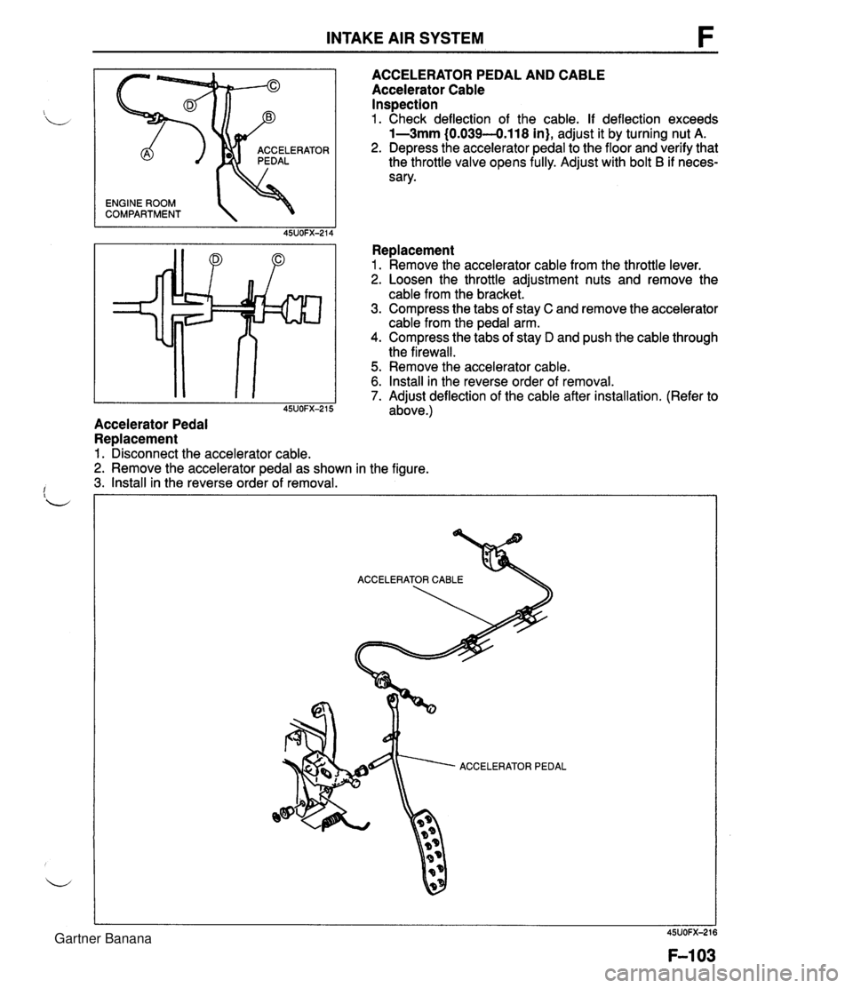
INTAKE AIR SYSTEM ENGINE ROOM COMPARTMENT 'OR ACCELERATOR PEDAL AND CABLE Accelerator Cable Inspection 1. Check deflection of the cable. If deflection exceeds 1-3mm (0.039-0.118 in), adjust it by turning nut A. 2. Depress the accelerator pedal to the floor and verify that the throttle valve opens fully. Adjust with bolt B if neces- sary. Replacement 1. Remove the accelerator cable from the throttle lever. 2. Loosen the throttle adjustment nuts and remove the cable from the bracket. 3. Compress the tabs of stay C and remove the accelerator cable from the pedal arm. 4. Compress the tabs of stay D and push the cable through the firewall. 5. Remove the accelerator cable. 6. Install in the reverse order of removal. 7. Adiust deflection of the cable after installation. (Refer to I 45~0~~-215 adbve.) Accelerator Pedal Replacement 1. Disconnect the accelerator cable. 2. Remove the accelerator pedal as shown in the figure. 3. Install in the reverse order of removal. ACCELERATOR PEDAL Gartner Banana