spark plugs MAZDA MX-5 1994 User Guide
[x] Cancel search | Manufacturer: MAZDA, Model Year: 1994, Model line: MX-5, Model: MAZDA MX-5 1994Pages: 1708, PDF Size: 82.34 MB
Page 188 of 1708

TROUBLESHOOTING GUIDE - TEP - 4 INSPECTION ACTION ;heck for correct intake manifold vacuum at idle Yes - No - Yes Go to next step Intake manifold vacuum: More than 450 mmHg I17.7 InHg} ,VACUUM GAUGE Low vacuum Check for air leakage of intake air system page F-100 Zheck for fuel injector operating sound at idle with sound scope or screwdriver Go to Step 7 Go to Step 6 Check if fuel injector resistance is OK us page F-119 Check if battery positive voltage exists at fuel injec- tor connector B terminal Yes - No - Yes - No Resistance: 12-1 6R e If OK, check wiring between PCME and fuel injector page F-7 Q If not OK, replace fuel injector us page F-119 Check wiring between PCME and fuel injector page F-7 Disconnect each fuel injector connector at idle and check if engine speed decreases equally each time Disconnect each high-tension lead at idle and :heck if engine speed decreases equally each time Q If OK, go to Step 9 Q If not OK, check fuel injector for fuel leakage page F-120 Go to step 8 Zheck if spark plugs are OK ILDUP PLUG GAP 1.0-l.lmrn [0.04-.043 in) DAMAGE AND DETERIORATION Check if PCME terminal voltages are OK (1 R, IT, 2Q2Q and 2X) page F-146 Yes - No - Yes Check for correct engine compression Section B + If OK, replace fuel injector page F-119 Q If not OK, check for cause (Refer to Section 6) Section B Repair, clean, or replace Go to next step No - Yes Check for cause (Refer to "Check Point for Each Termi- nal") page F-148 Check purge solenoid valve = page F-132 - - Check if vacuum is felt at purge solenoid valveat Go to next step Try known good PCME and check if condition im- proves page F-144 Gartner Banana
Page 190 of 1708

TROUBLESHOOTING GUIDE INSPECTION ACTION ;heck if PCME terminal voltages are OK 1 R, IT, 20.20 and 2Q) page F-146 :heck if strong blue spark is visible at each discon- iected high-tension lead while cranking engine ;heck for fuel injector operating sound at each fuel njector at idle ;heck if battery positive voltage exists at fuel injec- :or connector B terminal :heck if spark plugs are OK PLUG GAP 14-1 .l mm (0.040-4.043 in) DAMAGE AND DETERIORATION :heck for EGR system malfunction uz page F-124 Yes No - Yes - No - Yes No - Yes - No - Yes No - Yes - No - Go to next step Check for cause (Refer to "Check Point for Each Termi- nal") @&T page F-148 Go to next step Check ignition system (Refer to Troubleshooting "Misfire") I@? Section G Go to Step 9 Go to Step 8 Check if fuel injector resistance is OK @&T page F-119 Resistance: 12-1 6R o If OK, check wiring between PCME and fuel injector page F-7 0 If not OK, replace fuel injector @&T page F-119 Check wiring between PCME and fuel injector I@? page F-7 Go to next step Repair or replace Section G Repair or replace Go to next step Gartner Banana
Page 207 of 1708

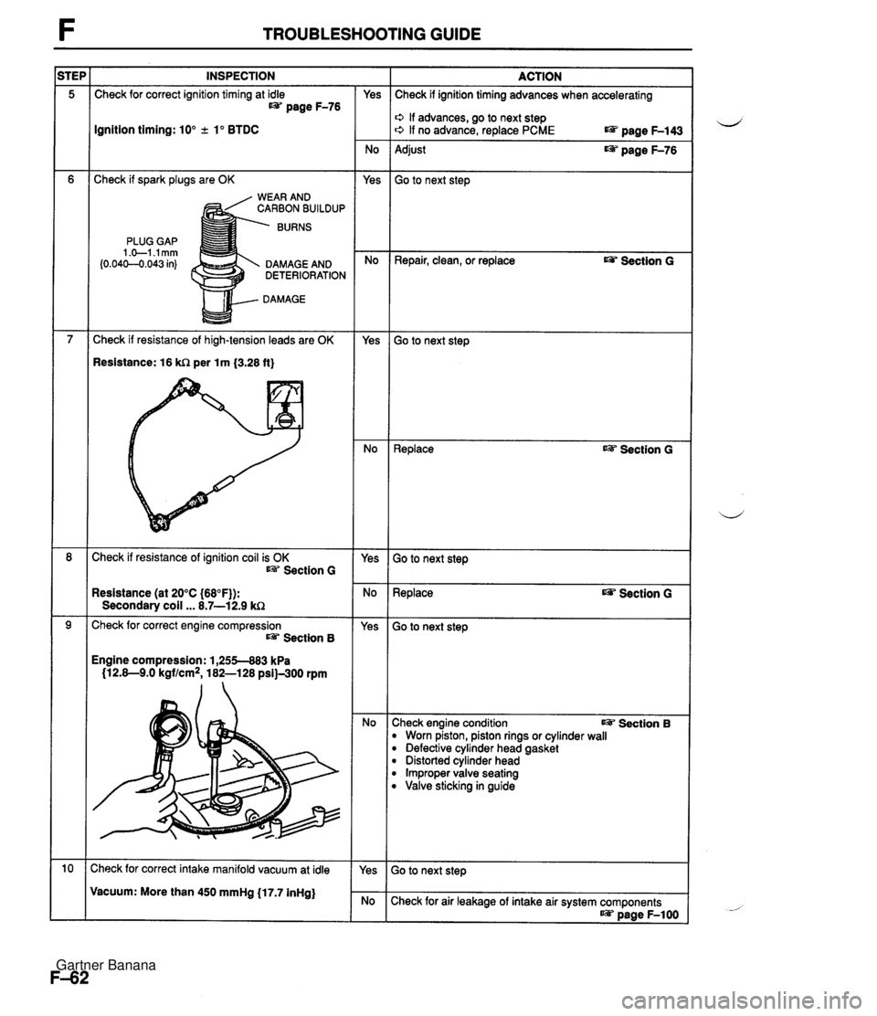
TROUBLESHOOTING GUIDE INSPECTION :heck for correct ignition timing at idle page F-76 gnition timing: 10" .t lo BTDC ;heck if spark plugs are OK RBON BUILDUP PLUG GAP 1 .O-l.lmrn b.040--0.043 in} DAMAGE AND DETERIORATION DAMAGE :heck if resistance of high-tension leads are OK lesistance: 16 k!2 per 1 m (3.28 ft) :heck if resistance of ignition coil is OK Section G lesistance (at 20°C (66°F)): Secondary coil ... 8.7-12.9 'heck for correct engine compression Section B ngine compression: 1,255483 kPa (12.8-9.0 kgf/cm2, 182-128 psiE.300 rpm Yes No Yes No - Yes Yes No - Yes - No ACTION Check if ignition timing advances when accelerating s, If advances, go to next step +, If no advance, replace PCME terminal voltages page F-143 Adjust page F-76 Go to next step Repair, clean, or replace us Section G Go to next step Replace w Section G Go to next step Replace Section G 30 to next step Zheck engine condition w Section B D Worn piston, piston rings or cylinder wall D Defective cylinder head gasket Distorted cylinder head Improper valve seating B Valve sticking in guide Gartner Banana
Page 211 of 1708

TROUBLESHOOTING GUIDE INSPECTION Check for correct ignition timing at idle t@= page F-76 Ignition timing: 10" +. lo BTDC Check if spark plugs are OK WEAR AND CARBON BUILDUP BURNS PLUG GAP 1 .+I .I mm (0.04C-O.043 in) DAMAGE AND DETERIORATION DAMAGE Check if resistance of high-tension leads are OK Resistance: 16 kR per lm {3.28 ft} Check if resistance of ignition coil is OK Section G Resistance (at 20°C {68"F)): Secondary coil ... 8.7-12.9 kC2 Check for correct engine compression Section 8 Engine compression: 1,255-883 kPa (12.8-9.0 kgf/cm2, 182-128 psi)-300 rpm :heck for correct intake manifold vacuum at idle Vacuum: More than 450 mmHg (17.7 inHg) - Yes - No Yes - No - Yes - No - Yes - No - Yes - No - Yes ACTION Check if ignition timing advances when accelerating o If advances, go to next step o If no advance, replace PCME page F-143 Adjust page F-76 Go to next step Repair, clean, or replace Ojp Section G Go to next step ~eplace as? Section G Go to next step Replace Section G - -- Go to next step :heck engine condition I@= Section B B Worn piston, piston rings or cylinder wall B Defective cylinder head gasket B Distorted cylinder head B Improper valve seating B Valve sticking in guide Check for air leakage of intake air system components as? page F-1 00 Gartner Banana
Page 239 of 1708

F ON-BOARD DIAGNOSIS SYSTEM CODE No. 17 (HEATED OXYGEN SENSOR: INVERSION) I Circuit Diagram INSPECTION Warm up engine and run it at 2,500-3,000 rpm for 3 min. HEATED OXYGEN SENSOR ACTION Does monitor lamp of Self-Diagnosis Checker illu- minate at idle? Are spark plugs clean? Is heated oxygen sensor voltage OK? * page F-156 Is same Code No. present after performing after repair procedure? ESI= page F-90 Is there continuity between heated oxygen sensor and PCME terminal 2N? Is PCME terminal 2N voltage OK? * page F-146 PCME Yes No Yes No Yes No Yes No Yes No Yes No Go to next step Check for air leak in vacuum hoses or emission compo- nents Check for contaminated heated oxygen sensor Check for insufficient fuel injection Go to next step Clean or replace spark plugs Go to next step Replace heated oxygen sensor page F-156 Go to next step Check for short circuit in wiring from heated oxygen sen- sor to PCME terminal 2N Go to next step Check for open circuit in wiring from heated oxygen sen- sor to PCME Replace PCME page F-143 Check for short circuit in wiring from heated oxygen sen- sor to PCME Gartner Banana
Page 324 of 1708

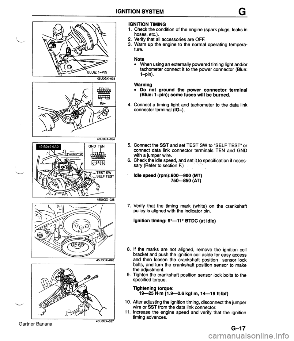
IGNITION SYSTEM G GND TEN I I I IGNITION TIMING 1. Check the condition of the engine (spark plugs, leaks in hoses, etc.). 2. Verify that all accessories are OFF. 3. Warm up the engine to the normal operating tempera- ture. Note When using an externally powered timing light and/or tachometer connect it to the power connector (Blue: l-pin). Warning Do not ground the power connector. terminal (Blue: l-pin); some fuses will be burned. 4. Connect a timing light and tachometer to the data link connector terminal (IG-). 5. Connect the SST and set TEST SW to "SELF TEST" or connect data link connector terminals TEN and GND with a jumper wire. 6. Check the idle speed, and set it to specification if neces- sary (Refer to section F.) ' Idle speed (rpm):800-900 (MT) 75-50 (AT) 7. Verify that the timing mark (white) on the crankshaft pulley is aligned with the indicator pin. Ignition timing: 9"-11" BTDC (at idle) 8. If the marks are not aligned, remove the ignition coil bracket and push the ignition coil aside for easy access and then loosen the crankshaft position sensor lock bolts, and turn the crankshaft position sensor to make the adjustment. 9. Tighten the crankshaft position sensor lock bolts to the specified torque. Tightening torque: 19-25 N-m (1 3-2.6 kgf~m, l4--19 ft.lbf) 10. After adjusting the ignition timing, disconnect the jumper wire or SST from the data link connector. 11. Increase the engine speed and verify that the ignition timing advances. Gartner Banana
Page 325 of 1708

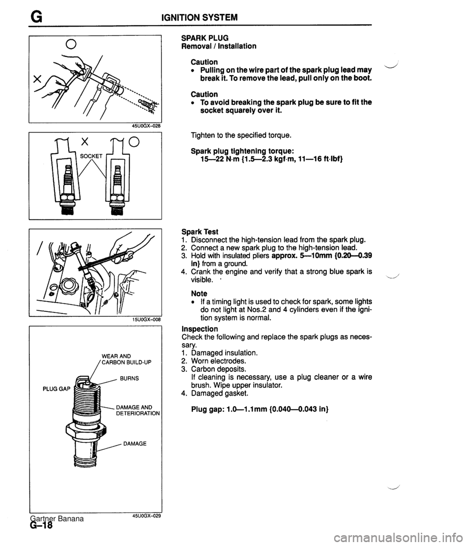
G IGNITION SYSTEM BURNS PLUG GAP DAMAGE AND DETERIORATION DAMAGE SPARK PLUG Removal 1 Installation Caution Pulling on the wire part of the spark plug lead may i/ break it. To remove the lead, pull only on the boot. Caution To avoid breaking the spark plug be sure to fit the socket squarely over it. Tighten to the specified torque. Spark plug tightening torque: 15--22 N-m (1.5--2.3 kgf-m, 11-16 ft-lbf) Spark Test 1. Disconnect the high-tension lead from the spark plug. 2. Connect a new spark plug to the high-tension lead. 3. Hold with insulated pliers approx. 5-10mm (0.20-4.39 in) from a ground. 4. Crank the engine and verify that a strong blue spark is visible. . -.d' Note If a timing light is used to check for spark, some lights do not light at Nos.:! and 4 cylinders even if the igni- tion system is normal. Inspection Check the following and replace the spark plugs as neces- sary. 1. Damaged insulation. 2. Worn electrodes. 3. Carbon deposits. If cleaning is necessary, use a plug cleaner or a wire brush. Wipe upper insulator. 4. Damaged gasket. Plug gap: 1 .O-1 .l mm (0.040-0.043 in) Gartner Banana