suspension MAZDA MX-5 1994 User Guide
[x] Cancel search | Manufacturer: MAZDA, Model Year: 1994, Model line: MX-5, Model: MAZDA MX-5 1994Pages: 1708, PDF Size: 82.34 MB
Page 733 of 1708

Before beginning any service procedure. refer to section T of this manual for I air bag system service warnings and audio antitheft system alarm conditions . INDEX ....................................... R- 2 OUTLINE ..................................... R- 4 SPECIFICATIONS ........................... R- 4 TROUBLESHOOTING GUIDE .................. R- 5 WHEEL ALIGNMENT .......................... R- 6 PRE-INSPECTION .......................... R- 6 FRONT WHEEL ALIGNMENT ................. R- 6 .................. REAR WHEEL ALIGNMENT R- 9 FRONT SUSPENSION (DOUBLE-WISHBONE) ... R-11 PREPARATION ............................. R-11 SHOCK ABSORBER AND SPRING ............ R-11 LOWER ARM ............................... R-15 UPPER ARM ............................... R-17 STABILIZER ................................ R-19 CROSSMEMBER ........................... R-20 REAR SUSPENSION (DOUBLE-WISHBONE) .... R-21 PREPARATION ............................. R-21 SHOCK ABSORBER AND SPRING ............ R-22 LOWER ARM ............................... R-23 UPPER ARM ............................... R-24 STABILIZER ................................ R-25 CROSSMEMBER ........................... R-26 25UORX-001 Gartner Banana
Page 734 of 1708

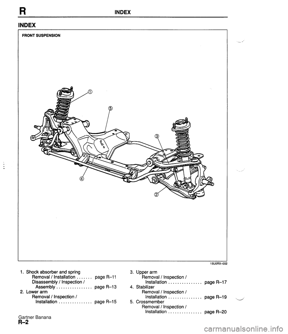
INDEX INDEX FRONT SUSPENSION 1. Shock absorber and spring 3. Upper arm ....... Removal / Installation page R-1 1 Removal / Inspection / ............... Disassembly / Inspection / Installation page R-17 ................ Assembly page R-13 4. Stabilizer 2. Lower arm Removal / Inspection 1 Removal / Inspection 1 Installation ............... page R-19 -, ............... Installation page R-15 5. Crossmember Removal / Inspection / Installation ............... page R-20 Gartner Banana
Page 735 of 1708

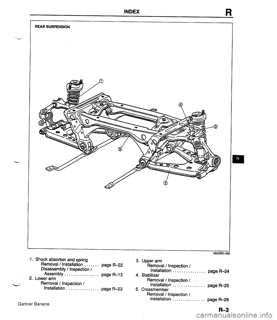
INDEX R REAR SUSPENSION 1. Shock absorber and spring 3. Upper arm Removal I Installation ....... page R-22 Removal 1 Inspection 1 Disassembly 1 Inspection / Installation ............... page R-24 Assembly ................ page R-13 4. Stabilizer 2. Lower arm Removal 1 Inspection 1 L' Removal I Inspection / Installation ............... page R-25 Installation ............... page R-23 5. Crossmember Removal / Inspection 1 Installation ............... page R-26 Gartner Banana
Page 736 of 1708

OUTLINE OUTLINE SPECIFICATIONS Front Suspension - Transmission item (Stabilizer Specifications MT I AT - I Susoension tvoe I . , . , I . , Shock absorber Cylindrical double acting, low-pressure-gas charged I Double-wishbone TY pe Torsion bar Coil spring I - Diameter mm linl I 20.0 10.79) Identification mark color 19.0 (0.75) White Wire diameter mm (in) Coil inner diameter mm {in) I Blue Free length mm {in) Coil number 11 .O (0.43) 83 i3.27) 11 .O (0.43) 83 (3.27) 292.5 (1 1 32) 6.32 3 +. 3 (0.12 + 0.12) 0°18' + 18' Total toe-in I - I 35UORX-001 Rear Suspension 302.0 (1 1.89) 6.32 mm {in) degree Total toe-in (per side) 1 degree Front wheel alignment (Unladedt1) 0°09' +. 09' Caster anglee3 4"26' +. 45' Kingpin angle 11 "20' Maximum steering angle Transmission Specifications MT I AT Item Differential - Suspension type Inner Outer "TORSEN" LSD 1 Standard Double-wishbone Coil springs 370 23' a 2" 32" 32' -t 2" Camber anglee2 Torsion bar 12.0 (0.47) 1 11.0 (0.43) 1 11 .O (0.43) Cylindrical double acting, low-pressure-gas charged - Stabilizer Identification mark color Wire diameter mm {in) 0°24' + 45' Type Diameter mm {in) I Coil number I 7.68 I 7.96 I Shock absorber Yellow 10.1 {0.40} Coil inner diameter mm {in) Free length mm {in) Green 10.2 {0.40) 35UORX-002 *I Fuel tank full; radiator coolant and engine oil at specified levels; spare tire, jack, and tools in designated positions. '2 Difference between left and right must not exceed I O. '3 Difference between left and right must not exceed 1'30'. "TORSEN" is a registered trademark of ZEXEL-GLEASON USA.INC 83 I3.27) 348.5 j13.72) Rear wheel alignment (Unladed*') 83 (3.27) 356.5 (1 4.04) Total toe-in Total toe-in (per side) mm (in) degree degree 3 -c 3 (0.12 + 0.121 0°18' + 18' 0°09' + 09' Camber angle*2 -0°43' 2 30' Gartner Banana
Page 737 of 1708

TROUBLESHOOTING GUIDE TROUBLESHOOTING GUIDE Problem General instabllity Body "rolls" "Heavy" steering wheel operation Steering wheel pulls to one side Excessive steering wheel play Body leans Abnormal noise from suspension system Shake (Steering wheel tibrates upldown) Shimmy (Steering wheel vibrates leftlright) Possible cause Weak coil spring Malfunction of shock absorber Worn or damaged stabilizer and/or suspension arm bushings Worn or damaged upper or lower arm ball joint Improperly adjusted wheel alignment Weak stabilizer Worn or damaged stabilizer and/or suspension arm bushings Insufficiently lubricated or stuck upper arm lower arm ball joint lmproperly adjusted wheel alignment Weak coil spring Worn or damaged stabilizer and/or suspension arm bushings Deformed upper or lower arm or knuckle Loose upper or lower arm bushing Worn or damaged upper or lower arm bushing Worn or damaged upper or lower arm ball joint Weak coil spring Weak stabilizer andlor suspension arm bushings Loose mounting component Poorly lubricated or worn upper or lower arm ball joint Malfunction of shock absorber Worn or damaged stabilizer and/or suspension arm bushings Excessive tire or wheel runout Loose lug nuts Unbalanced wheel@) Cracked or worn engine mounting rubber Cracked or worn steering gear mounting rubber Loose steering gear mounting bolts Stuck or damaged steering ball joint Excessive tire or wheel runout Loose lug nuts Unbalanced wheel(s) Insufficient tire pressure Unevenly worn tires Malfunction of shock absorber Loose shock absorber mounting bolts Stuck or damaged upper or lower arm ball joint Cracked or worn suspension bushings Damaged or worn front wheel bearing lmproperly adjusted front wheel alignment Action Replace Replace Replace Replace Adjust Replace Replace Replace Adjust Replace Replace Replace Replace Replace Replace Replace Replace Tighten Replace Replace Replace Replace Tighten Adjust or replace Replace Replace Tighten Replace Replace Tighten Adjust or replace Adjust Replace Replace Tighten Replace Replace Replace Adjust Page R-13 R-12,22 R-16, 18, 19, 23,24,25 section M R-15,17 R- 6 R-19,25 R-16, 18,19, 23, 24,25 section M R-15,17 R- 6 R-13 R-16, 18,19, 23, 24,25 R-15,17 section M R-16,18 R-16,18 R-15,17 R-13 R-16, 18, 19, 23,24,25 section M 7 R-15,17 R-l2,22 R-16, 18,19, 23,24,25 section M - section Q section Q section B section N section N section N - section Q section Q section Q section Q R-l2,22 R-12,22 R-15, 17 R-16,18,19 section M R- 6 15UORX-00 Gartner Banana
Page 743 of 1708

FRONT SUSPENSION (DOUBLE-WISHBONE) FRONT SUSPENSION (DOUBLE-WISHBONE) PREPARATION SST 49 0727 575 Puller, socket oint Attachment, steering worm bearing preload measuring 49 GO34 1 A0 Compressor, coil spring Screw (Part of - 49 GO34 1 AO) - Wrench, flare nut For removal of lower arm ball joint For 1 49 GO34 101 49 01 18 850C Puller, ball joint For inspection of upper arm ball joint 49 H028 301 Installer, dust boot For 1 49 GO34 103 removal and installation of coil spring Body (Part of 49 GO34 1 AO) For removal and installation of brake pipe removal and installation of coil spring SHOCK ABSORBER AND SPRING Removal / Installation 1. Jack up the front of the vehicle and support it with safety stands. 2. Remove the undercover. 3. Remove the band for the wheel speed sensor harnes. 4. Remove in the order shown in the figure, referring to Removal Note. Arm (Part of 49 GO34 I AO) 5. Inspect all parts and repair or replace as necessary. 6. Install in the reverse order of removal. For removal of upper arm ball joint For installation of front lower arm boot For removal and installation of coil spring For removal and installation of coil spring 7. Loosely tighten the shock absorber, upper arm, stabilizer control link, and stabilizer bracket bolts. Tighten all other nuts and bolts to the specified torques. 8. Install the band for the wheel speed sensor. 9. Lower the vehicle. 10. With the vehicle unloaded, tighten the upper arm and shock absorber bolts to the specified torques. - 11. Adjust the front wheel alignment. (Refer to page R-6.) 25UORX406 Gartner Banana
Page 744 of 1708

FRONT SUSPENSION (DOUBLE-WISHBONE) 1. Wheel and tire 2. Stabilizer control link bolt 3. Upper arm ball joint Removal Note ........ 4. Mounting plate nut 5. Shock absorber and spring Removal Note ............. page R-12 Disassembly l Inspection I , . . page R-18 Assembly ................ page R-13 Removal note Shock absorber and spring 1. Loosen the lower arm bolts. Caution Do not lower the arm excessively, which may damage the brake hose. L 2. Lower the lower arm to remove the shock absorber. Gartner Banana
Page 745 of 1708

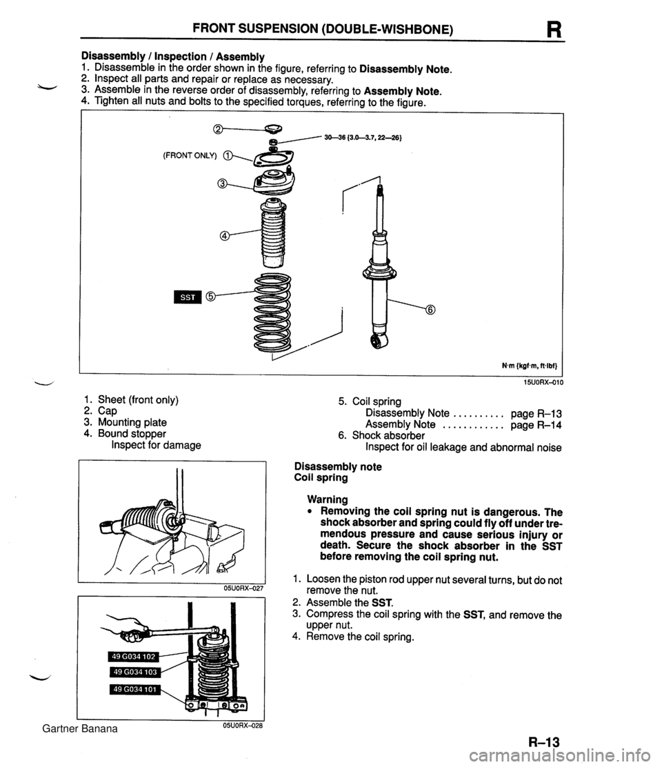
FRONT SUSPENSION (DOUBLE-WISHBONE) R Disassembly I Inspection I Assembly 1. Disassemble in the order shown in the figure, referring to Disassembly Note. 2. lnspect all parts and repair or replace as necessary. 3. Assemble in the reverse order of disassembly, referring to Assembly Note. 4. Tighten all nuts and bolts to the specified torques, referring to the figure. (FRONT ONLY) & 3 1. Sheet (front only) 2. Cap 3. Mounting plate 4. Bound stopper lnspect for damage 5. Coil spring .......... Disassembly Note page R-13 ............ Assembly Note page R-14 6. Shock absorber lnspect for oil leakage and abnormal noise Disassembly note Coil spring Warning Removing the coil spring nut is dangerous. The shock absorber and spring could fly off under tre- mendous pressure and cause serious injury or death. Secure the shock absorber in the SST before removing the coil spring nut. 1. Loosen the piston rod upper nut several turns, but do not remove the nut. 2. Assemble the SST. 3. Compress the coil spring with the SST, and remove the upper nut. 4. Remove the coil spring. Gartner Banana
Page 746 of 1708

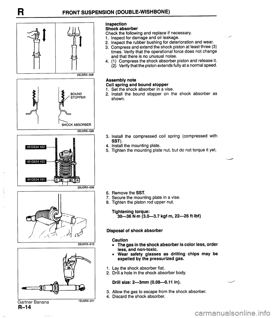
I3 FRONT SUSPENSION (DOUBLE-WISHBONE) I t'- SHOCK ABSORBER 05UORX-02 Inspection Shock absorber Check the following and replace if necessary. 1. lnspect for damage and oil leakage. 2. lnspect the rubber bushing for deterioration and wear. 3. Compress and extend the shock piston at least three (3) times. Verify that the operational force does not change and that there is no unusual noise. 4. (1) Compress the shock absorber piston and release it. (2) Verify that the piston extends fully at a normal speed. Assembly note Coil spring and bound stopper 1. Set the shock absorber in a vise. 2. Install the bound stopper on the shock absorber as shown. 3. lnstall the compressed coil spring (compressed with SST). 4. Install the mounting plate. 5. Tighten the mounting plate nut, but do not torque it yet. 6. Remove the SST. 7. Secure the mounting plate in a vise. 8. Tighten the piston rod upper nut. Tightening torque: 30-36 N.m (3.0-3.7 kgf.m, 22-26 ftdbf) Disposal of shock absorber Caution The gas in the shock absorber is color less, order less, and non-toxic. Wear safety glasses as drilling chips may be expelled by the pressurized gas. 1. Lay the shock absorber flat. 2. Drill a hole in the shock absorber body. Drill size: 2-3mm (0.08-0.11 in). 3. Allow the gas to escape from the shock absorber. 4. Discard the shock absorber. Gartner Banana
Page 747 of 1708

FRONT SUSPENSION (DOUBLE-WISHBONE) LOWER ARM Removal / lnspection I Installation 1. Jack up the front of the vehicle and support it with safety stands. 2. Remove the undercover. 3. Remove in the order shown in the figure, referring to Removal Note. 4. lnspect all parts and repair or replace as necessary. 5. Install in the reverse order of removal, referring to lnstallation Note. 6. Loosely tighten the lower arm, shock absorber, and stabilizer control link bolts. Tighten all other nuts and bolts to the specified torque with the vehicle unladen. 7. Lower the vehicle. 8. With the vehicle unloaded, tighten the lower arm, shock absorber, and stabilizer control link bolts to the - specified torques. 9. Adjust the front wheel alignment. (Refer to page R-6.) 1. Wheel and tire 15UORX-012 5. Ball joint dust boot 2. Stabilizer control link bolt emo oval ~ote ............. page R-16 3. Shock absorber bolt Installation Note ........... page R-16 u 4. Lower arm ball joint 6. Lower arm Removal Note ............. page R-16 Inspect for damage and cracks Inspection ................. page R-16 7. Lower arm bushing (front and rear) lnspect for deterioration and wear Gartner Banana