suspension MAZDA MX-5 1994 Owner's Manual
[x] Cancel search | Manufacturer: MAZDA, Model Year: 1994, Model line: MX-5, Model: MAZDA MX-5 1994Pages: 1708, PDF Size: 82.34 MB
Page 748 of 1708
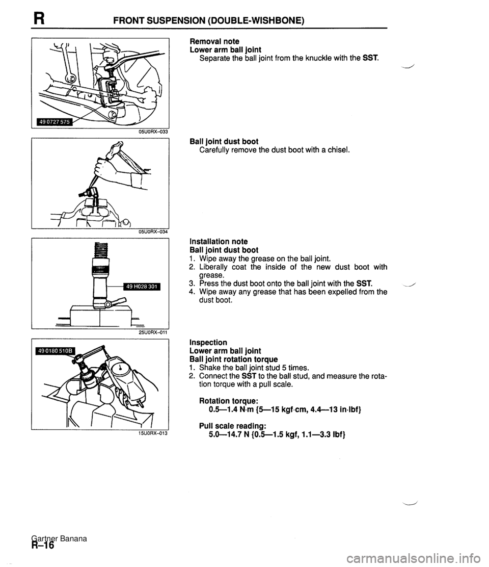
FRONT SUSPENSION (DOUBLE-WISHBONE) Removal note Lower arm ball joint Separate the ball joint from the knuckle with the SST. ./-' Ball joint dust boot Carefully remove the dust boot with a chisel. Installation note Ball joint dust boot 1. Wipe away the grease on the ball joint. 2. Liberally coat the inside of the new dust boot with grease. 3. Press the dust boot onto the ball joint with the SST. J 4. Wipe away any grease that has been expelled from the dust boot. Inspection Lower arm ball joint Ball joint rotation torque 1. Shake the ball joint stud 5 times. 2. Connect the SST to the ball stud, and measure the rota- tion torque with a pull scale. Rotation torque: 0.5-1.4 N.m (5--15 kgf.cm, 4.4--13 in-lbf) Pull scale reading: 5.b14.7 N (0.5-1.5 kgf, 1.1-3.3 Ibf) Gartner Banana
Page 749 of 1708

FRONT SUSPENSION (DOUBLE-WISHBONE) R UPPER ARM Removal I Inspection I Installation 1. Jack up the front of the vehicle and support it with safety stands. L/ 2. Remove the undercover. 3. Remove the band for the wheel speed sensor harness. 4. Remove in the order shown in the figure, referring to Removal Note. 5. lnspect all parts and repair or replace as necessary. 6. Install in the reverse order of removal, referring to Installation Note. 7. Loosely tighten the upper arm and shock absorber bolts. Tighten all other nuts and bolts to the specified torques. 8. Install the band for the wheel speed sensor harnes. 9. Lower the vehicle. 10. With the vehicle unloaded, tighten the upper arm and shock absorber bolts to the specified torques. 11. Adjust the front wheel alignment. (Refer to page R-6.) 25UORX-01 1. Wheel and tire 5, Ball ioint dust boot Upper arm ball joint demoval ~ote ............. page R-18 Removal Note ............. page R-18 Installation Note ........... page R-18 Shock absorber bolt 6. Upper arm bushing (front and rear) 4. Upper arm Inspect for deterioration and damage Inspect for damage and cracks Gartner Banana
Page 750 of 1708
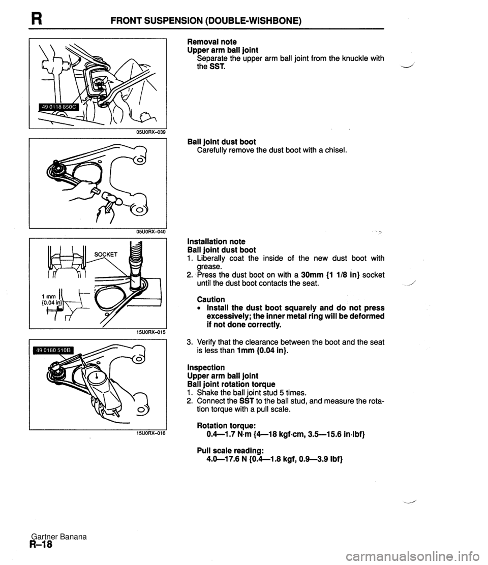
R FRONT SUSPENSION (DOUBLE-WISHBONE) I0.04 in} Removal note Upper arm ball joint Separate the upper arm ball joint from the knuckle with the SST. Ball joint dust boot Carefully remove the dust boot with a chisel. Installation note Ball joint dust boot 1. Liberally coat the inside of the new dust boot with grease. 2. Press the dust boot on with a 30mm (1 118 in) socket until the dust boot contacts the seat. Caution Install the dust boot squarely and do not press excessively; the inner metal ring will be deformed if not done correctly. 3. Verify that the clearance between the boot and the seat is less than 1mm (0.04 in). Inspection Upper arm ball joint Ball joint rotation torque 1. Shake the ball joint stud 5 times. 2. Connect the SST to the ball stud, and measure the rota- tion torque with a pull scale. Rotation torque: O.4--1.7 N.m {&-I 8 kgf.cm, 3.5--15.6 in4 bf) Pull scale reading: 4.b17.6 N (0.4--1.8 kgf, 0.9--3.9 Ibf) Gartner Banana
Page 751 of 1708
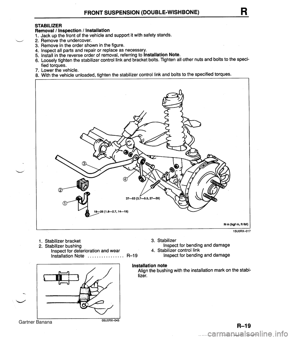
FRONT SUSPENSION (DOUBLE-WISHBONE) R STABILIZER Removal / Inspection / installation 1. Jack up the front of the vehicle and support it with safety stands. - 2. Remove the undercover. 3. Remove in the order shown in the figure. 4. lnspect all parts and repair or replace as necessary. 5. Install in the reverse order of removal, referring to Installation Note. 6. Loosely tighten the stabilizer control link and bracket bolts. Tighten all other nuts and bolts to the speci- fied torques. - 7. Lower the vehicle. 8. With the vehicle unloaded, tighten the stabilizer control link and bolts to the specified torques. 1. Stabilizer bracket 3. Stabilizer 2. Stabilizer bushing Inspect for bending and damage Inspect for deterioration and wear 4. Stabilizer control link Installation Note . . . . . . . . . . . . . . . . R-19 Inspect for bending and damage Installation note Align the bushing with the installation mark on the stabi- lizer. Gartner Banana
Page 752 of 1708

FRONT SUSPENSION (DOUBLE-WISHBONE) CROSSMEMBER Removal I Inspection 1 lnstallation Note 4 Use a container or rags to collect the power steering fluid when disconnecting the power steering pipes. 1. Jack up the vehicle. 2. Remove the wheels and the undercover. 3. Support the engine with a hoist. 4. Lower the crossmember and other suspension parts as an assembly, and then separate the parts. 5. Remove in the order shown in the figure. 6. lnspect all parts and repair or replace as necessary. 7. Loosely tighten the stabilizer bracket, upper arm, and lower arm bolts. Tighten all other nuts and bolts to the specified torques. 8. Lower the vehicle. 9. With the vehicle unloaded, tighten the stabilizer bracket, upper arm, and lower arm bolts to the specified torques. 10. Adjust the front wheel alignment. (Refer to page R-6.) 11. Bleed the air from the brake system. (Refer to section P.) 12. Bleed the air from the Power Steering System. (Refer to section N.) Q - re-no ~L1.3--11.W, Okl-m} 94-1;2 (9.Cll.5,69--83) 1 &26 {1.&2.7,14--19) 1 S21 (1 3-- 1. Brake pipe Removal / lnstallation . . . . . . . . . Section P 2. Pinion shaft bolt Removal / lnstallation . . . . . . . . Section N 3. Power steering pipe Removal 1 lnstallation . . . . . . . . Section N 4. Shock absorber bolt 5. Stabilizer bracket bolt 6. Upper arm bolt 7. Performance rod 8. Adjusting cam bolt 9. Steering gear bracket bolt 10. Front crossmember assembly lnspect for damage Gartner Banana
Page 753 of 1708
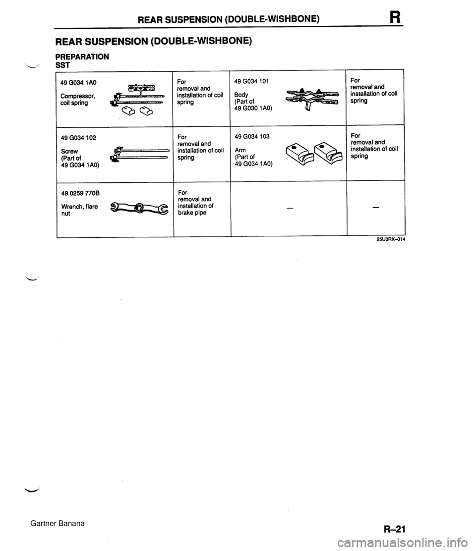
REAR SUSPENSION (DOUBLE-WISHBONE) R REAR SUSPENSION (DOUBLE-WISHBONE) PREPARATION L., SST Compressor, coil spring Screw (Part of 49 GO34 1 AO) 49 0259 7708 Wrench, flare nut For 1 49 GO34 I01 For 1 49 GO34 103 removal and installation of coil spring Body (Part of 49 GO30 I AO) For removal and installation of brake pipe removal and installation of coil spring For removal and installation of coil spring Arm (Part of 49 GO34 1 AO) For removal and installation of coil spring Gartner Banana
Page 754 of 1708

R REAR SUSPENSION (DOUBLE-WISHBONE) SHOCK ABSORBER AND SPRING Removal / Installation 1. Jack up the front of the vehicle and support it with safety stands. 2. Remove in the order shown in the figure, referring to Removal Note. 3. Inspect all parts and repair or replace as necessary. 4. Install in the reverse order of removal. 5. Loosely tighten the stabilizer control link bolt. Tighten all other nuts and bolts to the specified torques. 6. Lower the vehicle. 7. With the vehicle unloaded, tighten the stabilizer control link bolt to the specified torques. 8. Adjust the rear wheel alignment. (Refer to page R-9.) Nm (kgfm, ft4bf) 1. Wheel and tire 2. Filler pipe protector (left side) 3. Stabilizer control link bolt 4. Shock absorber and spring Removal Note . . . . . . . . . . . . . page R-22 Disassembly l Inspection / Assembly . . . . . . . . . . . . . . . . page R-13 Removal note Shock absorber and spring Caution Do not lower the arms excessively, which may damage the brake hose. 1. Loosen the upper arm and Adjusting cam nuts. 2. Lower the upper and lower arms to remove the shock absorber and spring. Gartner Banana
Page 755 of 1708

REAR SUSPENSION (DOUBLE-WISHBONE) LOWER ARM Removal / Inspection / Installation 1. Jack up the rear of the vehicle and support it with safety stands. 2. Remove in the order shown in the figure. 3. lnspect all parts and repair or replace as necessary. 4. Install in the reverse order of removal. 5. Loosely tighten the lower arm, shock absorber, and stabilizer control link bolts. Tighten all other nuts and bolts to the specified torques. 6. Lower the vehicle. 7. With the vehicle unloaded, tighten the lower arm, shock absorber, and stabilizer control link bolts to the - specified torques. 8. Adiust the rear wheel alignment. (Refer to page R-9.) 1. Wheel and tire 2. Stabilizer control link bolt 3. Shock absorber bolt 4. Lower arm lnspect for damage and cracks 5. Lower arm bushing (crossmember side and knuckle side) lnspect for deterioration and wear Gartner Banana
Page 756 of 1708

REAR SUSPENSION (DOUBLE-WISHBONE) UPPER ARM Removal I Inspection I Installation 1. Jack up the rear of the vehicle and support it with safety stands. 2. Remove in the order shown in the figure. 3. lnspect all parts and repair or replace as necessary. 4. Install in the reverse order of removal. 5. Loosely tighten the upper arm bolts. Tighten all other nuts and bolts to the specified torques. 6. Lower the vehicle. 7. With the vehicle unloaded, tighten the upper arm bolts to the specified torques. 8. Adjust the rear wheel alignment. (Refer to page R-9.) REPLACE 1. Wheel and tire 2. Upper arm lnspect for damage and cracks 3. Upper arm bushing lnspect for deterioration and wear Gartner Banana
Page 757 of 1708
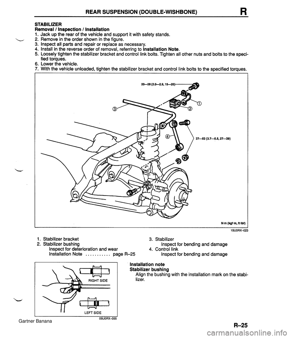
REAR SUSPENSION (DOUBLE-WISHBONE) R STABILIZER Removal / Inspection / lnstallation 1. Jack up the rear of the vehicle and support it with safety stands. 2. Remove in the order shown in the figure. 3. lnspect all parts and repair or replace as necessary. 4. Install in the reverse order of removal, referring to lnstallation Note. 5. Loosely tighten the stabilizer bracket and control link bolts. Tighten all other nuts and bolts to the speci- fied toraues. 6. Lower the vehicle. 7. With the vehicle unloaded, tighten the stabilizer bracket and control link bolts to the specified torques. 1. Stabilizer bracket 3. Stabilizer 2. Stabilizer bushing Inspect for bending and damage Inspect for deterioration and wear 4. Control link Installation Note . . . . . . . . . . . page R-25 Inspect for bending and damage RIGHT SlDE s I I LEFT SIDE 05UORX-055 lnstallation note Stabilizer bushing Align the bushing with the installation mark on the stabi- lizer. Gartner Banana