wheel MAZDA MX-5 1994 User Guide
[x] Cancel search | Manufacturer: MAZDA, Model Year: 1994, Model line: MX-5, Model: MAZDA MX-5 1994Pages: 1708, PDF Size: 82.34 MB
Page 159 of 1708
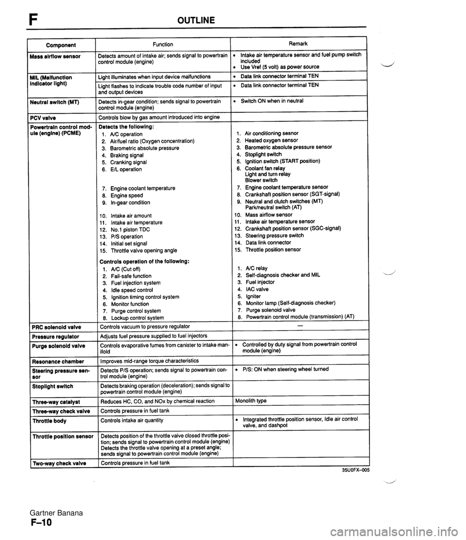
Neutral swltch (MT) 7 PCV valve Powertrain control mod- ule (engine) (PCME) Purge solenoid valve Resonance chamber Steering pressure sen- Stoplight swltch I Throttle posltion sensor r [Two-way check valve Function jetects amount of intake air; sends signal to powertrain :ontrol module (engine) Li~ht illuminates when input device malfunctions - Light flashes to indicate trouble code number of input and output devices Detects in-gear condition; sends signal to powertrain :ontrol module (engine) - Controls blow by aas amount introduced into engine Detects the followlng: 1. A/C operation 2. Airlfuel ratio (Oxygen concentration) 3. Barometric absolute pressure 4. Braking signal 5. Cranking signal 6. EIL operation 7. Engine coolant temperature 8. Engine speed 9. In-gear condition 10. lntake air amount 11, lntake air temperature 12. No.1 piston TDC 13. PIS operation 14. Initial set signal 15. Throttle valve opening angle Controls operatlon of the followlng: 1. AIC (Cut off) 2. Fail-safe function 3. Fuel injection system 4. ldle speed control 5. Ignition timing control system 6. Monitor function 7. Purge control system 8. Lockup control svstem Controls vacuum to pressure regulator -- Adjusts fuel pressure supplied to fuel injectors Controls evaporative fumes from canister to intake man- ifold -- lm~roves mid-ranae torque characteristics -. Detects PIS operation; sends signal to powertrain con- trol module (engine) -- Detects braking operation (deceleration); sends signal to powertrain control module (engine) Reduces HC, CO, and NOx by chemical reaction Controls pressurein fuel tank Controls intake air quantity Detects position of the throttle valve closed throttle posi- tion; sends signal to powertrain control module (engine) Detects the throttle valve opening at a preset angle; sends si~nal to powertrain control module (engine) controls pressure in fuel tank Remark lntake air temperature sensor and fuel pump switch included Use Vref (5 volt) as power source ' Data link connector terminal TEN ' Data link connector terminal TEN Switch ON when in neutral 1, Air conditioning sesnor 2. Heated oxygen sensor 3. Barometric absolute pressure sensor 4. Stoplight switch 5. Ignition switch (START position) 6. Coolant fan relay Light and turn relay Blower switch 7. Engine coolant temperature sensor 8. Crankshaft position sensor (SGT-signal) 9. Neutral and dutch switches (MT) Parklneutral switch (AT) 10. Mass airflow sensor 11, lntake air temperature sensor 12. Crankshaft position sensor (SGC-signal) 13. Steering pressure switch 14. Data link connector 15. Throttle position sensor 1. NC relay 2. Self-diagnosis checker and MIL 3. Fuel injector 4. IAC valve 5. Igniter 6. Monitor lamp (Self-diagnosis checker) 7. Purge solenoid valve 8. Powertrain control module (transmission) (AT) D Controlled by duty signal from powertrain control module (engine) D PIS: ON when steering wheel turned Monolith type D Integrated throttle position sensor, Idle air control valve, and dashpol Gartner Banana
Page 307 of 1708

CONTROL SYSTEM Replacement Replace the neutral switch as shown in the figure. STEERING PRESSURE SENSOR Inspection 1. Disconnect the steering pressure sensor connector. 2. Connect an ohmmeter to the switch. 3. Start the engine and let it idle. Check continuity of the switch while turning the steering wheel. PIS 1 Continuity Turnina Yes " I t ~ot turning I NO 4. If not as specified, replace the steering pressure sensor. Replacement Replace the steering pressure sensor as shown in the figure. Gartner Banana
Page 336 of 1708

Before beginning any service procedure. refer to section T of this manual for air bag system service warnlngs and audio antitheft system alarm conditions . i, CLUTCH INDEX ....................................... H- 2 OUTLINE ..................................... H- 3 SPECIFICATIONS ........................... H- 3 TROUBLESHOOTING GUIDE .................. H- 3 CLUTCH FLUID ............................... H- 4 ............................. PREPARATION H- 4 ............................ REPLACEMENT H- 4 .............................. CLUTCH PEDAL H- 5 .............................. ADJUSTMENT H- 5 REMOVAL / INSPECTION / INSTALLATION .... H- 6 ................. CLUTCH MASTER CYLINDER H- 7 PREPARATION ............................. H- 7 REMOVAL / INSTALLATION .................. H- 8 AIR BLEEDING ............................. H- 9 OVERHAUL ................................ H-10 CLUTCH RELEASE CYLINDER ................ H-12 PREPARATION ............................. H-12 REMOVAL / INSTALLATION .................. H-12 AIR BLEEDING (REFER TO PAGE H-9.) OVERHAUL ............................... H-13 CLUTCH UNIT ................................ H-14 PREPARATION ............................. H-14 REMOVAL / INSTALLATION .................. H-14 CLUTCH RELEASE COLLAR .................. H-17 INSPECTION ............................... H-17 CLUTCH COVER ............................. H-17 INSPECTION ............................... H-17 CLUTCH DISC ................................ H-17 INSPECTION ............................... H-17 PILOT BEARING .............................. H-18 INSPECTION ............................... H-18 FLYWHEEL ................................... H-18 INSPECTION ............................... H-18 35UOHX-001 Gartner Banana
Page 337 of 1708

H INDEX INDEX 1 . Clutch pedal ................ Adjustment page H- 5 Removal / Inspection / ............... Installation page H- 6 2. Clutch master cylinder ....... Removal I Installation page H- 8 .................. Overhaul page H-10 ............... Air bleeding page H- 9 3. Clutch release cylinder ....... Removal I Installation page H-12 .................. Overhaul page H-13 ............... Air bleeding page H- 9 4. Clutch release collar ....... Removal / Installation page H-14 ................. Inspection page H-17 SERVICE, SECTION F 5. Clutch release fork ....... Removal / Installation page H-14 6. Clutch cover ....... Removal / Installation page H-14 ................. Inspection page H-17 7. Clutch disc ....... Removal 1 Installation page H-14 ................. Inspection page H-17 8. Pilot bearing ....... Removal I Installation page H-14 ................. Inspection page H-18 9. Flywheel Removal / Installation ....... page H-14 ................. Inspection page H-18 Gartner Banana
Page 338 of 1708

OUTLINE, TROUBLESHOOTING GUIDE H OUTLINE SPECIFICATIONS I Clutch control L' Clutch cover Clutch disc Clutch pedal - Enginerrransmission BP DOHC item - M15M-D 1 Master cvlinder inne I Hydraulic Inner diameter mm {in) I 150 (5.91) I Pressure plate side I n n rn cr Tvpe . . Set load N {kgf, Ibf) Outer diameter mm {in) Pedal ratio 6.13 Full stroke mm {in) I 120 (4.72) Diaphraam spring .-.- 4,310 (440,968) 21 5 18.46) . - Height mm {in) * diameter mm {in) TROUBLESHOOTING GUIDE . - I 75--185 i6.89--7.283 15.87 (0.625) . - Release cylinder inner diameter mm {in) Clutch fluid I Problem I Possible Cause 19.05 i0.750) FMVSS116 DOT-3 Clutch disc facing surface hardened or oil on surface Pressure plate damaged u Diaphragm spring damaged or weak lnsufficient clutch pedal play I Slipping I Clutch disc facing worn excessively I Flywheel damaged Faulty disengagement I Clutch disc damaged or excessive runout Clutch disc spines rusted or worn Oil on clutch disc facing Diaphragm spring weak Excessive clutch pedal play Insufficient clutch fluid Leakage of clutch fluid I 1 Clutch disc facing hardened or damaged Clutch vibrates when accelerating I I Clutch disc facing rivets loose Oil on clutch disc facing Torsion dampers weak Clutch pedal stlcks Abnormal noise Pressure plate damaged or excessive runout Flywheel surface hardened or damaged Loose or worn engine mount Pedal shaft not pro~erlv lubricated Clutch release collar damaged Poor lubrication of release collar sleeve Torsion dampers weak Excessive crankshaft end play I I Pilot bearing worn or damaged I I Worn ~ivot points of release fork Action Replace Repair or replace Repair or replace Replace Adjust ~ebair or replace Replace Remove rust or replace Repair or replace Replace Adjust Add fluid Locate and repair or replace Repair or replace Replace Repair or replace Replace Replace Repair or replace Tighten or replace Lubricate or replace Replace Lubricate or replace Replace Repair Replace Repair or replace Page H-14 H-14 H-14 H-14 H-14 H-14 section B H- 6 H-14 H-14 H-14 section B H-14 H-14 45UOHX-OC Gartner Banana
Page 350 of 1708
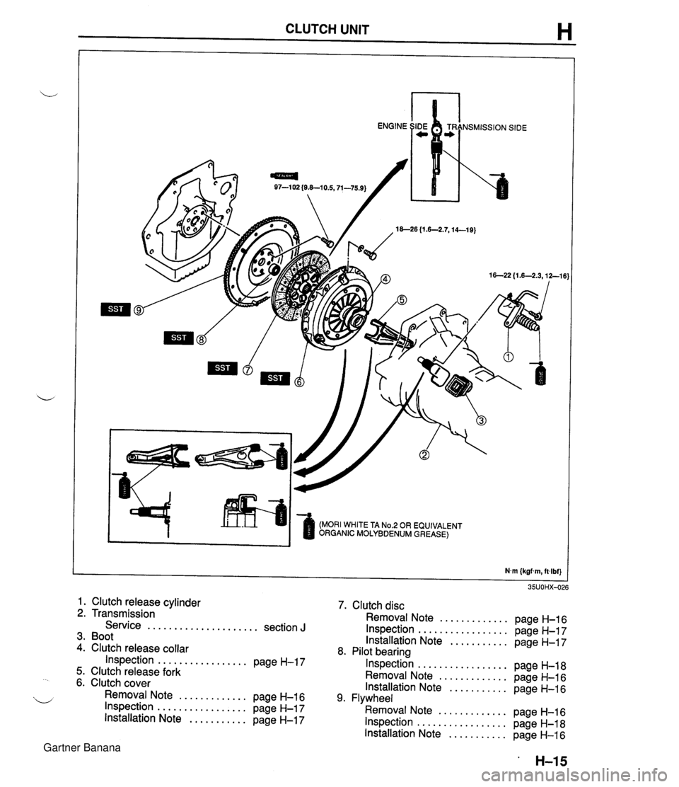
CLUTCH UNIT H 97-1 02 {O&-10.5,71-75.9) 18--26 {I .6-2.7,14-19) (MORI WHITE TA No.2 OR EQUIVALENT ORGANIC MOLYBDENUM GREASE) 1. Clutch release cylinder 2. Transmission Service ..................... section J 3. Boot 4. Clutch release collar Inspection ................. page H-17 5. Clutch release fork 6. Clutch cover Removal Note ............. page H-16 Inspection ................. page H-17 Installation Note ........... page H-17 7. Clutch disc Removal Note ............. page H-16 Inspection ................. page H-17 Installation Note ........... page H-17 8. Pilot bearing Inspection ................. page H-18 Removal Note ............. page H-16 Installation Note ........... page H-16 9. Flywheel Removal Note ............. page H-16 Inspection ................. page H-18 Installation Note ........... page H-16 Gartner Banana
Page 351 of 1708
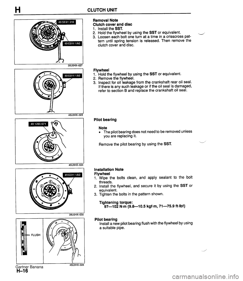
H CLUTCH UNIT Removal Note Clutch cover and disc 1 . Install the SST. 2. Hold the flywheel by using the SST or equivalent. e 3. Loosen each bolt one turn at a time in a crisscross pat- tern until spring tension is released. Then remove the clutch cover and disc. Flywheel 1. Hold the flywheel by using the SST or equivalent. 2. Remove the flywheel. 3. Inspect for oil leakage from the crankshaft rear oil seal. If there is any such leakage or if the oil seal is damaged, refer to section B and replace the crankshaft oil seal. Pilot bearing Note The pilot bearing does not need to be removed unless you are replacing it. Remove the pilot bearing by using the SST. L' Installation Note Flywheel 1. Wipe the bolts clean, and apply sealant to the bolt threads. 2. Install the flywheel, and secure it by using the SST or equivalent. 3. Tighten the bolts in the pattern shown. Tightening torque: 97-1 02 N.m (9.8-1 0.5 kgf.m, 71-75.9 ft-lbf) Pilot bearing Install a new pilot bearing flush with the flywheel by using a suitable pipe. Gartner Banana
Page 352 of 1708
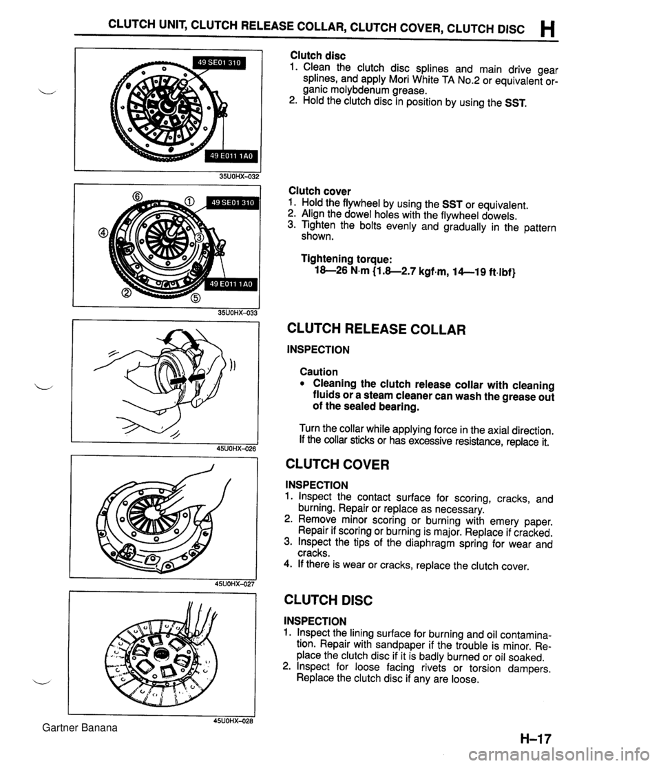
CLUTCH UNIT, CLUTCH RELEASE COLLAR, CLUTCH COVER, CLUTCH DlSC H Clutch disc 1. Clean the clutch disc splines and main drive gear splines, and apply Mori White TA No.2 or equivalent or- ganic molybdenum grease. 2. Hold the clutch disc in position by using the SST. Clutch cover 1. Hold the flywheel by using the SST or equivalent. 2. Align the dowel holes with the flywheel dowels. 3. Tighten the bolts evenly and gradually in the pattern shown. Tightening torque: 18-26 N.m (1.8-2.7 kgf.m, 14--19 ft.lbf} CLUTCH RELEASE COLLAR INSPECTION Caution Cleaning the clutch release collar with cleaning fluids or a steam cleaner can wash the grease out of the sealed bearing. Turn the collar while applying force in the axial direction. If the collar sticks or has excessive resistance, replace it. CLUTCH COVER INSPECTION 1. lnspect the contact surface for scoring, cracks, and burning. Repair or replace as necessary. 2. Remove minor scoring or burning with emery paper. Repair if scoring or burning is major. Replace if cracked. 3. lnspect the tips of the diaphragm spring for wear and cracks. 4. If there is wear or cracks, replace the clutch cover. I I 45UOHX-027 CLUTCH DlSC INSPECTION 1. lnspect the lining surface for burning and oil contamina- tion. Repair with sandpaper if the trouble is minor. Re- place the clutch disc if it is badly burned or oil soaked. 2. lnspect for loose facing rivets or torsion dampers. Replace the clutch disc if any are loose. Gartner Banana
Page 353 of 1708
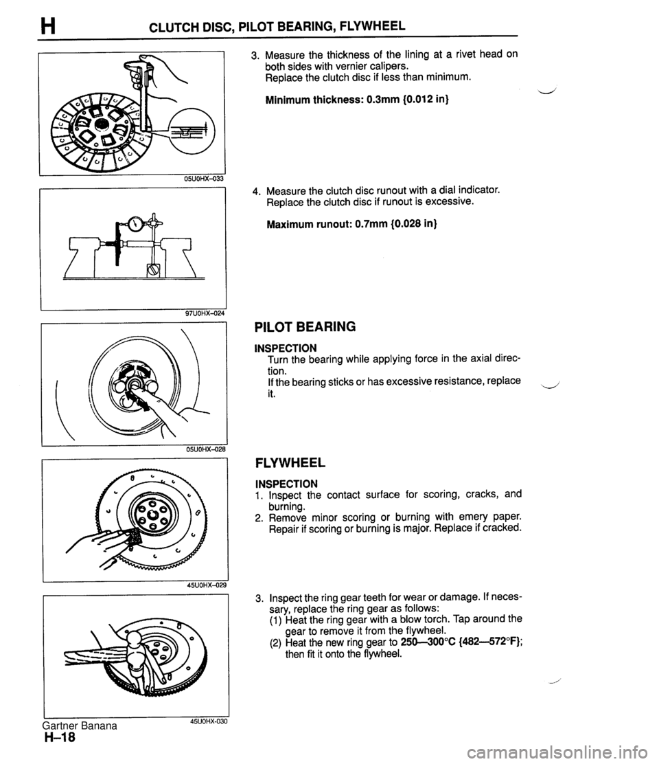
H CLUTCH DISC, PILOT BEARING, FLYWHEEL 3. Measure the thickness of the lining at a rivet head on both sides with vernier calipers. Replace the clutch disc if less than minimum. Minimum thickness: 0.3mm (0.012 in) 4. Measure the clutch disc runout with a dial indicator. Replace the clutch disc if runout is excessive. Maximum runout: 0.7mm (0.028 in) PILOT BEARING INSPECTION Turn the bearing while applying force in the axial direc- tion. If the bearing sticks or has excessive resistance, replace it. FLYWHEEL INSPECTION 1. lnspect the contact surface for scoring, cracks, and burning. 2. Remove minor scoring or burning with emery paper. Repair if scoring or burning is major. Replace if cracked. 3. lnspect the ring gear teeth for wear or damage. If neces- sary, replace the ring gear as follows: (1) Heat the ring gear with a blow torch. Tap around the gear to remove it from the flywheel. (2) Heat the new ring gear to 250--300°C (482--572°F); then fit it onto the flywheel. Gartner Banana
Page 354 of 1708
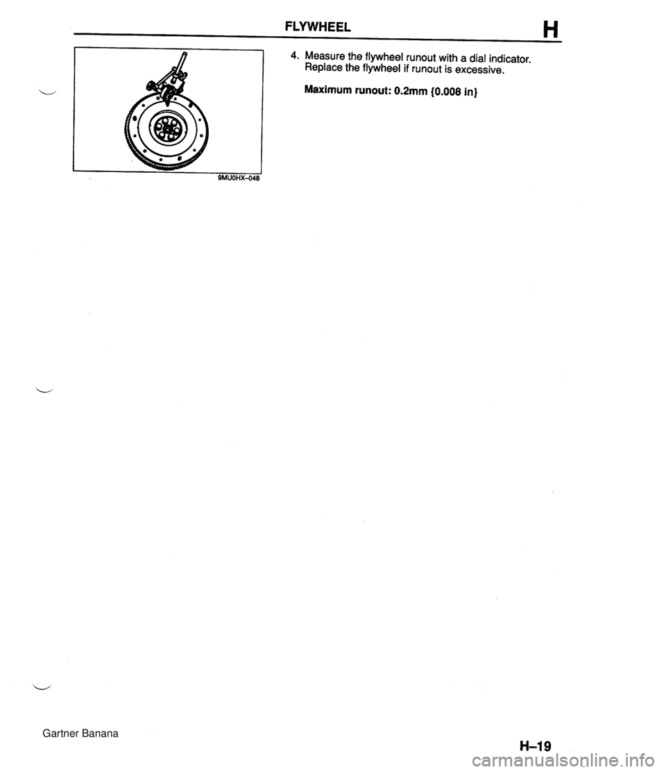
FLYWHEEL H 4. Measure the flywheel runout with a dial indicator. Replace the flywheel if runout is excessive. Maximum runout: 0.2mm (0.008 in) 9MUOHX-048 Gartner Banana