wheel MAZDA MX-5 1994 Owner's Manual
[x] Cancel search | Manufacturer: MAZDA, Model Year: 1994, Model line: MX-5, Model: MAZDA MX-5 1994Pages: 1708, PDF Size: 82.34 MB
Page 409 of 1708
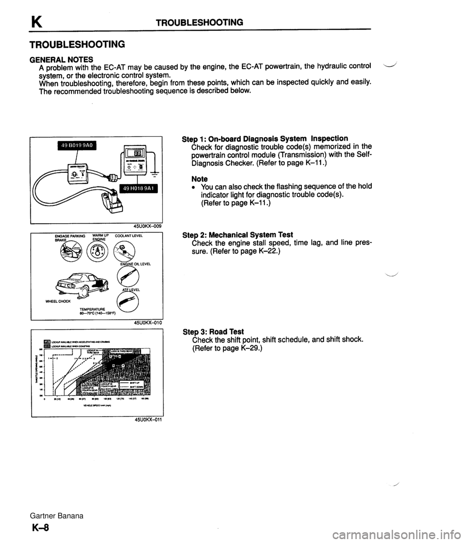
K TROUBLESHOOTING TROUBLESHOOTING GENERAL NOTES A problem with the EC-AT may be caused by the engine, the EC-AT powertrain, the hydraulic control LJ system, or the electronic control system. When troubleshooting, therefore, begin from these points, which can be inspected quickly and easily. The recommended troubleshooting sequence is described below. WHEEL CHOCK 63 TEMPERATURE w-7u'C (1461WF) Step 1 : On-board Diagnosis System Inspection Check for diagnostic trouble code(s) memorized in the powertrain control module (Transmission) with the Self- Diagnosis Checker. (Refer to page K-11 .) Note You can also check the flashing sequence of the hold indicator light for diagnostic trouble code(s). (Refer to page K-1 1 .) Step 2: Mechanical System Test Check the engine stall speed, time lag, and line pres- sure. (Refer to page K-22.) Step 3: Road Test Check the shift point, shift schedule, and shift shock. (Refer to page K-29.) Gartner Banana
Page 414 of 1708
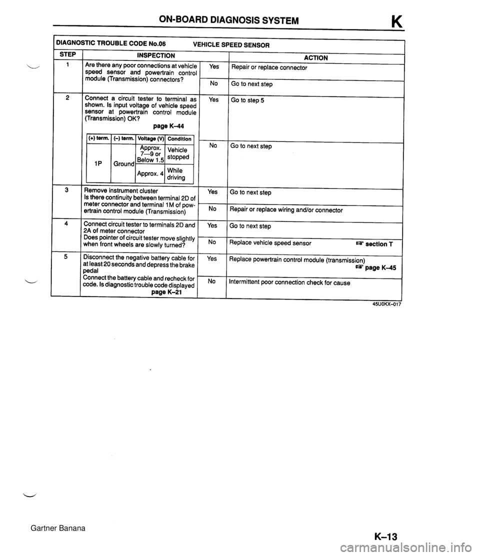
ON-BOARD DIAGNOSIS SYSTEM K )IAGNOSTIC TROUBLE CODE N0.06 VEHICLE SPEED SENSOR INSPECTION STEP ACTION Repair or replace connector Are there any poor connections at vehicle speed sensor and powertrain control module (Transmission) connectors? Yes Go to next step Connect a circuit tester to terminal as shown. Is input voltage of vehicle speed sensor at powertrain control module (Transmission) OK? page K-44 Yes Go to step 5 1 (+) term. I (-) term. ( Voltage (v)( Condition I Go to next step Below 1.5 While Remove instrument cluster Is there continuity between terminal 2D of meter connector and terminal 1 M of pow- ertrain control module (Transmission) Yes Go to next step Repair or replace wiring and/or connector Connect circuit tester to terminals 2D and 2A of meter connector Does pointer of circuit tester move slightly when front wheels are slowly turned? Yes Go to next step Replace vehicle speed sensor section T Disconnect the negative battery cable for at least 20 seconds and depress the brake pedal Connect the battery cable and recheck for code. Is diagnostic trouble code displayed Dane K-21 Yes Replace powertrain control module (transmission) page K-45 Intermittent poor connection check for cause Gartner Banana
Page 423 of 1708

K MECHANICAL SYSTEM TEST MECHANICAL SYSTEM TEST PREPARATION SST STALL TEST 49 0378 400A Gauge set, oil pressure 49 801 9 901 Gauge, oil pressure For oil pressure test For oil pressure test This test is performed to determine if there is slippage of the friction elements or malfunction of the hy- draulic components. Preparation 1. Check the engine coolant, engine oil, and ATF levels before testing. 2. Warm the engine thoroughly to raise the ATF temperature to operating level (50--80°C, 122-176°F). 3. Engage the parking brake and use wheel chocks at the front and rear of the wheels. ENGAGE PARKING BRAKE WARM UP ENGINE COOLANT LEVEL ENGINE OIL LEVEL TEMPERATURE 60-70°C (1 40-1 58°F) ATF LEVEL Gartner Banana
Page 436 of 1708

AUTOMATIC TRANSMISSION FLUID (ATF) K AUTOMATIC TRANSMISSION FLUID (ATF) ATF Inspection Level 1. Park the vehicle on level ground. 2. Apply the parking brake and position wheel chocks se- curely to prevent the vehicle from rolling. 3. Warm up the engine until the ATF reaches 60-70°C (1 40-1 58°F). 4. While depressing the brake pedal, shift the selector lever to each range (P-L), pausing momentarily in each range. 5. Shift back to P. Note In some cases it may be necessary to inspect the ATF in the cool range 15-25°C (59-77"F) before warm- ing up the engine. 6. Ensure that the ATF level is in the HOT (65°C) range. Add ATF to the specification, if necessary. ATF type: DexronQII or M-I11 Condition Determine whether the transmission should be disas- sembled by noting. 1. If the ATF is muddy or varnished. 2. If the ATF smells strange or unusual. Gartner Banana
Page 586 of 1708
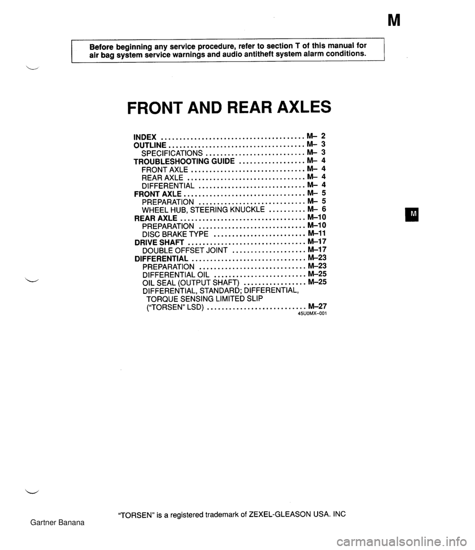
Before beginning any service procedure. refer to section T of this manual for air bag system service warnings and audio antitheft system alarm conditions . FRONT AND REAR AXLES ....................................... INDEX M- 2 ..................................... OUTLINE M- 3 SPECIFICATIONS ........................... M- 3 TROUBLESHOOTING GUIDE .................. M- 4 ............................... FRONT AXLE M- 4 ................................ REAR AXLE M- 4 ............................. DIFFERENTIAL M- 4 ................................. FRONT AXLE M- 5 PREPARATION ............................. M- 5 WHEEL HUB. STEERING KNUCKLE .......... M- 6 .................................. REAR AXLE M-10 PREPARATION ............................. M-10 ......................... DISC BRAKE TYPE M-11 ................................ DRIVE SHAFT M-17 .................... DOUBLE OFFSET JOINT M-17 ............................... DIFFERENTIAL M-23 PREPARATION ............................. M-23 DIFFERENTIAL OIL ......................... M-25 ................. OIL SEAL (OUTPUT SHAFT) M-25 DIFFERENTIAL. STANDARD; DIFFERENTIAL. TORQUE SENSING LIMITED SLIP ("TORSEN" LSD) ........................... M-27 45UOMX-001 "TORSEN" is a registered trademark of ZEXEL-GLEASON USA . INC Gartner Banana
Page 588 of 1708

OUTLINE OUTLINE Front axle Rear axle Differentlal Drive shaft Item I Specifications TY pe Bearing Double-wishbone Angular ball bearing Maximum wheel bearing play mm {in} TY pe Bearing 0.05 {0.002} Double-wishbone Angular ball bearing Maximum wheel bearing play mm {in} Type Reduction gear Reduction ratio Oil I Viscosity 0.05 {0.002} -- ---- Differential gear Ring gear size mm {in} Grade Above -1 8°C {O°F}: SAE 90 Below -1 8°C {O°F}: SAE 80 Standard Hypoid gear Straight-bevel gear 182.88 {7.20) API service GL-5 I Capacity L {US qt. imp qt} I 1 .OO {I .06,0.88) "TORSEN" LSD Worm gear 4.100 TY ~e Length mm {in} Constant velocity (double offset) joint 640.6 I25.220) 45UOMX-00 Gartner Banana
Page 589 of 1708

TROUBLESHOOTING GUIDE TROUBLESHOOTING GUIDE FRONT AXLE I Problem Posslbk Cause Worn or damaged wheel bearing Worn or damaged wheel bearing Steering wheel vibration braking Action Replace Replace REAR AXLE Page M- 6 M-6 I Problem Possible Cause Bent drive shaft Page Action Replace I Abnormal nolse Worn or damaged wheel bearing Worn drive shaft spline Worn or deteriorated upper arm bushing M-13 Replace I M-17 Body "rolls" I Replace section R Body leans Weak upper arm bushing Abnormal nolse from suspension system Worn or deteriorated upper arm bushing DIFFERENTIAL Problem Posrlble Cause lnsufficient differential oil Incorrect differential oil lmproperly adjusted ring gear backlash Poor contact of ring gear teeth Worn or damaged side bearing Worn or damaged ring gear Worn or damaged drive pinion bearing Worn or damaged pinion and side gear (STANDARD) Worn or damaged gear in LSD assembly ("TORSEN" LSD) Seized side gear and case Worn side gear spline Worn pinion shaft Worn thrust washer Worn or damaged needle bearing ("TORSEN" LSD) lmproperly adjusted side gear backlash lmproperly adjusted drive pinion gear preload Action Add oil Replace Adjust Adjust Replace Replace Replace Replace Replace Page M-25 M-25 M40 M4l M-32 M-32 M-32 M-32 M-32 M-32 M-32 M-32 M-32 M-32 M-40 M-39 Abnormal nolse Replace Replace Replace Replace Replace Adjust Adjust Heat buildup lnsufficient differential oil lnsufficient drive pinion gear backlash Excessive bearing preload Add oil Adjust Adjust Oil leakage Excessive differential oil Loose differential carrier Worn or damaged oil seal Remove oil Tighten or repair Replace I - No dlfferentlal operation I Misassembled or damaged Repair Gartner Banana
Page 591 of 1708
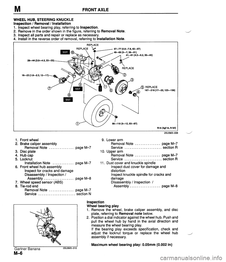
FRONT AXLE WHEEL HUB, STEERING KNUCKLE Inspection / Removal / lnstallation 1. lnspect wheel bearing play, referring to Inspection. 2. Remove in the order shown in the figure, referring to Removal Note. 3. lnspect all parts and repair or replace as necessary. 4. Install in the reverse order of removal, referring to Installation Note. 25UOMX-OC 1. Front wheel 9. Lower arm 2. Brake caliper assembly Removal Note .............. page M-7 3. Disc plate 4. Hub cap 5. Locknut Installation Note ............ page M-7 6. Front wheel hub assembly lnspect for cracks and damage Disassembly / Inspection / Assembly ................. page M-8 7. Wheel speed sensor (ABS) 8. Tie-rod end Removal Note .............. page M-7 Service ..................... section N .............. Removal Note page M-7 ..................... Service section R 10. Upper arm .............. Removal Note page M-7 ..................... Service section R 11. Dust cover and knuckle spindle lnspect dust cover for damage and distortion lnspect knuckle spindle for cracks and damage Disassembly / Inspection 1 ................. Assembly page M-8 lnspection Wheel bearing play 1. Remove the wheel, brake caliper assembly, and disc plate, referring to Removal note below. 2. Position a dial indicator against the wheel hub. Push and pull the wheel hub by hand in the axial direction and measure the wheel bearing play. If the bearing play exceeds specification, check and adjust the locknut torque or replace the wheel hub i assembly if necessary. Maximum wheel bearing play: 0.05mm i0.002 in) Gartner Banana
Page 593 of 1708
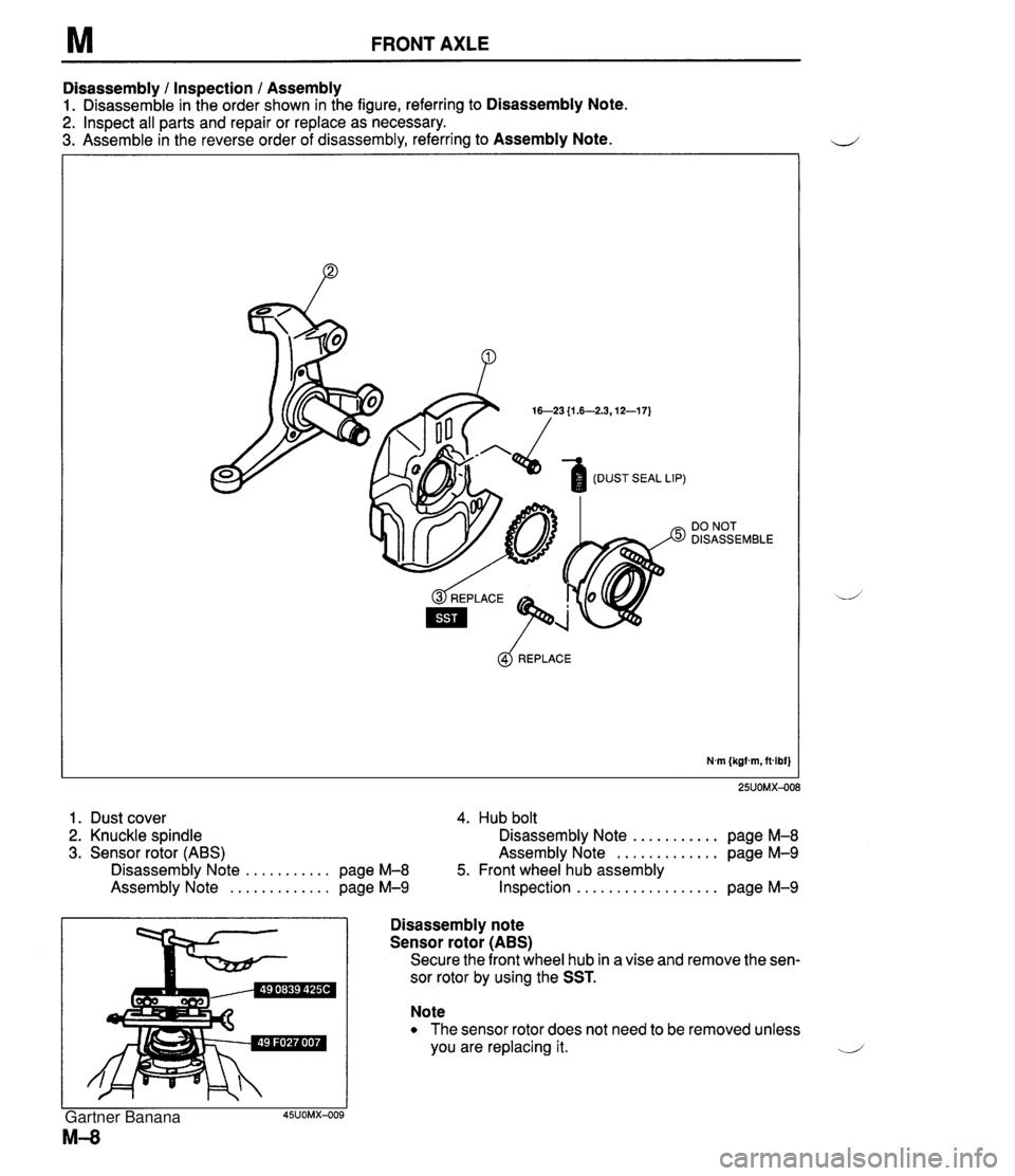
M FRONT AXLE Disassembly 1 Inspection 1 Assembly 1. Disassemble in the order shown in the figure, referring to Disassembly Note. 2. Inspect all parts and repair or replace as necessary. 3. Assemble in the reverse order of disassembly, referring to Assembly Note. DO NOT DISASSEMBLE @$ REPLACE N.m (kgfm, ftdbf} 1. Dust cover 4. Hub bolt 2. Knuckle spindle Disassembly Note ........... page M-8 3. Sensor rotor (ABS) Assembly Note ............. page M-9 Disassembly Note ........... page M-8 5. Front wheel hub assembly Assembly Note ............. page M-9 Inspection .................. page M-9 Disassembly note ' Sensor rotor (ABS) I Secure the front wheel hub in a vise and remove the sen- sor rotor by using the SST. Note The sensor rotor does not need to be removed unless you are replacing it. ..-.' Gartner Banana
Page 594 of 1708

FRONT AXLE M Hub bolts Note The hub bolts do not need to be removed unless you are replacing them. Remove the hub bolts with a press. Assembly note Hub bolts Install the new hub bolts with a press. Sensor rotor (ABS) Install a new sensor rotor by using the SST and a press. Inspection Front wheel hub assembly Inspect for damage. Gartner Banana